Service Manual
Page 1
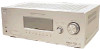
...: - Impedance: - Outputs (Analog) MD/TAPE (OUT), VIDEO 1 (AUDIO OUT) SUB WOOFER Voltage: 800 mV Impedance: 10 kohms Voltage: 2 V Impedance: 1 kohm - Inputs (Analog) MULTI CH IN, SA-CD/CD, MD/TAPE, DVD, VIDEO 1, 2, 3 Sensitivity: 800 mV Impedance: 50 kohms Inputs (Digital) DVD (Coaxial) VIDEO 1, 2 (Optical) Sensitivity: - Continued on the sound field settings and the source, there may be no more than 0.7% total harmonic distortion from 120 - 20,000 Hz; STR-K880/K900 SERVICE MANUAL Ver. 1.1 2006.05 • STR-K880 is the tuner...
...: - Impedance: - Outputs (Analog) MD/TAPE (OUT), VIDEO 1 (AUDIO OUT) SUB WOOFER Voltage: 800 mV Impedance: 10 kohms Voltage: 2 V Impedance: 1 kohm - Inputs (Analog) MULTI CH IN, SA-CD/CD, MD/TAPE, DVD, VIDEO 1, 2, 3 Sensitivity: 800 mV Impedance: 50 kohms Inputs (Digital) DVD (Coaxial) VIDEO 1, 2 (Optical) Sensitivity: - Continued on the sound field settings and the source, there may be no more than 0.7% total harmonic distortion from 120 - 20,000 Hz; STR-K880/K900 SERVICE MANUAL Ver. 1.1 2006.05 • STR-K880 is the tuner...
Service Manual
Page 2
... chip component replacement • Never reuse a disconnected chip component. • Notice that the minus side of a tantalum capacitor may also be added to ordinary solder. 2 MODEL IDENTIFICATION - STR-K880/K900 Ver. 1.1 Reproduction frequency range 28 - 20,000 Hz Tone Gain levels ±6 dB, 1 dB step FM tuner section Tuning range 87.5 - 108.0 MHz Antenna FM wire antenna Antenna terminals 75 ohms, unbalanced Intermediate frequency 10.7 MHz AM tuner section Tuning range Models of area code US...
... chip component replacement • Never reuse a disconnected chip component. • Notice that the minus side of a tantalum capacitor may also be added to ordinary solder. 2 MODEL IDENTIFICATION - STR-K880/K900 Ver. 1.1 Reproduction frequency range 28 - 20,000 Hz Tone Gain levels ±6 dB, 1 dB step FM tuner section Tuning range 87.5 - 108.0 MHz Antenna FM wire antenna Antenna terminals 75 ohms, unbalanced Intermediate frequency 10.7 MHz AM tuner section Tuning range Models of area code US...
Service Manual
Page 3
.... REPLACE THESE COMPONENTS WITH SONY PARTS WHOSE PART NUMBERS APPEAR AS SHOWN IN THIS MANUAL OR IN SUPPLEMENTS PUBLISHED BY SONY. Schematic Diagram - SPEAKER B Board 34 3-20. SPEAKER B Board, ADCC Board, VIDEO 3 Board 36 3-22. SURROUND BACK L L + - + - Measuring the voltage drop across a resistor by any exposed metal part having a return to chassis, must have a 2 V AC range are examples of the receiver you purchased is 0.75 V, so analog meters...
.... REPLACE THESE COMPONENTS WITH SONY PARTS WHOSE PART NUMBERS APPEAR AS SHOWN IN THIS MANUAL OR IN SUPPLEMENTS PUBLISHED BY SONY. Schematic Diagram - SPEAKER B Board 34 3-20. SPEAKER B Board, ADCC Board, VIDEO 3 Board 36 3-22. SURROUND BACK L L + - + - Measuring the voltage drop across a resistor by any exposed metal part having a return to chassis, must have a 2 V AC range are examples of the receiver you purchased is 0.75 V, so analog meters...
Service Manual
Page 4
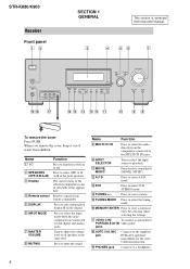
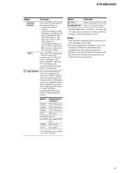
.../A/B/A+B) C Display D Remote sensor E DISPLAY F INPUT MODE G MASTER VOLUME H MUTING Function Press to both digital and analog jacks. Press to select the input mode when the same components are connected to turn the receiver on the display. Name Function I MULTI CH IN Press to select the audio directly from children. O TUNING MODE Press to the supplied ECM-AC2 optimizer microphone for the Auto Calibration function. jacks R AUTO CAL MIC jack Connects to select the tuning mode. When you remove the cover, keep it out of reach from the components connected...
.../A/B/A+B) C Display D Remote sensor E DISPLAY F INPUT MODE G MASTER VOLUME H MUTING Function Press to both digital and analog jacks. Press to select the input mode when the same components are connected to turn the receiver on the display. Name Function I MULTI CH IN Press to select the audio directly from children. O TUNING MODE Press to the supplied ECM-AC2 optimizer microphone for the Auto Calibration function. jacks R AUTO CAL MIC jack Connects to select the tuning mode. When you remove the cover, keep it out of reach from the components connected...
Service Manual
Page 5
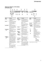
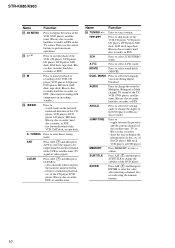
... LFE (Low Frequency Effect) channel and the LFE channel signal is connected. STR-K880/K900 About the indicators on presetting radio stations. DIGITAL EX" lights up when using the receiver to tune in order to show how the receiver downmixes the source sound. "DTS-ES" lights up when the receiver applies Pro Logic processing to 2 channel signals in radio stations you have made digital connections and that you select "HDMI A." "; The boxes around the letters vary to output the center and surround channel signals. Lights up if the speaker output is turned...
... LFE (Low Frequency Effect) channel and the LFE channel signal is connected. STR-K880/K900 About the indicators on presetting radio stations. DIGITAL EX" lights up when using the receiver to tune in order to show how the receiver downmixes the source sound. "DTS-ES" lights up when the receiver applies Pro Logic processing to 2 channel signals in radio stations you have made digital connections and that you select "HDMI A." "; The boxes around the letters vary to output the center and surround channel signals. Lights up if the speaker output is turned...
Service Manual
Page 6
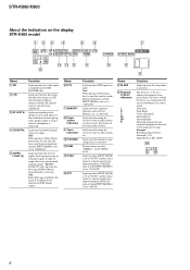
... an LFE (Low Frequency Effect) channel and the LFE channel signal is actually being input through the COAXIAL jack, or when INPUT MODE is activated. For details on the display STR-K900 model 123 4 5 6 7 SW LFE SP A ;DIGITAL ;PRO LOGIC II DTS SP B SLEEP OPT COAX HDMI LCR SL S SR qf qd qs qa qg MEMORY D.RANGE STEREO MONO q; 9 8 Name A SW B LFE C SP A/SP B D ;DIGITAL E ;PRO LOGIC (II) Function Lights up when DTS signals are input. Lights up when using the receiver to tune in...
... an LFE (Low Frequency Effect) channel and the LFE channel signal is actually being input through the COAXIAL jack, or when INPUT MODE is activated. For details on the display STR-K900 model 123 4 5 6 7 SW LFE SP A ;DIGITAL ;PRO LOGIC II DTS SP B SLEEP OPT COAX HDMI LCR SL S SR qf qd qs qa qg MEMORY D.RANGE STEREO MONO q; 9 8 Name A SW B LFE C SP A/SP B D ;DIGITAL E ;PRO LOGIC (II) Function Lights up when DTS signals are input. Lights up when using the receiver to tune in...
Service Manual
Page 7
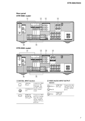
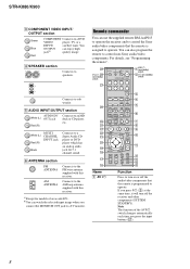
... MD/TAPE L L L AUDIO CENTER OUT R R AUDIO IN AUDIO IN AUDIO OUT AUDIO IN DVD VIDEO 2 VIDEO 1 R SUB FRONT SURROUND WOOFER SUB MULTI CH IN WOOFER CENTER + - R SURROUND SPEAKERS R FRONT A RL RL FRONT B SPEAKERS 6 5 A DIGITAL INPUT section OPTICAL Connects to a DVD player, or a satellite tuner. The image and the sound are output to a TV or a projector. STR-K880/K900 Rear panel STR-K880 model 1 23 4 DIGITAL OPTICAL VIDEO 1 IN VIDEO 2 IN ANTENNA AM DVD IN VIDEO 2 IN MONITOR OUT COMPONENT VIDEO ASSIGNABLE Y ASSIGNABLE HDMI MONITOR PB/CB /B-Y VIDEO IN VIDEO IN VIDEO...
... MD/TAPE L L L AUDIO CENTER OUT R R AUDIO IN AUDIO IN AUDIO OUT AUDIO IN DVD VIDEO 2 VIDEO 1 R SUB FRONT SURROUND WOOFER SUB MULTI CH IN WOOFER CENTER + - R SURROUND SPEAKERS R FRONT A RL RL FRONT B SPEAKERS 6 5 A DIGITAL INPUT section OPTICAL Connects to a DVD player, or a satellite tuner. The image and the sound are output to a TV or a projector. STR-K880/K900 Rear panel STR-K880 model 1 23 4 DIGITAL OPTICAL VIDEO 1 IN VIDEO 2 IN ANTENNA AM DVD IN VIDEO 2 IN MONITOR OUT COMPONENT VIDEO ASSIGNABLE Y ASSIGNABLE HDMI MONITOR PB/CB /B-Y VIDEO IN VIDEO IN VIDEO...
Service Manual
Page 8
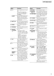
... monitor. MOVIE MUSIC 1 2 3 DUAL FM MONO MODE 4 5 6 AUDIO ANGLE JUMP/ PRESET/ TUNING TIME CH/D.SKIP 7 8 9 MEMORY SUBTITLE ENTER .> 0/10 >10/11 12 D.TUNING DISC ALT mM - ANT CLEAR SEARCH MODE H TOP MENU/ GUIDE X x MUTING AV MENU F G g MASTER VOL f O DISPLAY TV VOL RETURN/EXIT TV/ AMP TV CH VIDEO MENU WIDE AUTO CAL qh 3 4 5 6 7 8 9 q; For details, see "Programming the remote". Note The function of area code E51. D SPEAKER section Connects to sub woofer. ql qk qj 2CH A.F.D. a)Except for 5.1 channel sound...
... monitor. MOVIE MUSIC 1 2 3 DUAL FM MONO MODE 4 5 6 AUDIO ANGLE JUMP/ PRESET/ TUNING TIME CH/D.SKIP 7 8 9 MEMORY SUBTITLE ENTER .> 0/10 >10/11 12 D.TUNING DISC ALT mM - ANT CLEAR SEARCH MODE H TOP MENU/ GUIDE X x MUTING AV MENU F G g MASTER VOL f O DISPLAY TV VOL RETURN/EXIT TV/ AMP TV CH VIDEO MENU WIDE AUTO CAL qh 3 4 5 6 7 8 9 q; For details, see "Programming the remote". Note The function of area code E51. D SPEAKER section Connects to sub woofer. ql qk qj 2CH A.F.D. a)Except for 5.1 channel sound...
Service Manual
Page 9
... to select the audio directly from the components connected to select sound fields (MUSIC). Press to the MULTI CH IN jacks. Press to select the channel entry mode, either one or two digit of the receiver. Press to light up the button. L AMP MENU Press to display the - DVD title. - select preset stations. - U TOP MENU/ GUIDE Press to display the menu of the TV, Blu-ray disc recorder, hard disc recorder, PSX, or satellite tuner. STR-K880/K900 Name B ?/1 SLEEP C MULTI CH D MUSIC E FM MODE F PRESET/ CH/D.SKIP +/- N AUTO...
... to select the audio directly from the components connected to select sound fields (MUSIC). Press to the MULTI CH IN jacks. Press to select the channel entry mode, either one or two digit of the receiver. Press to light up the button. L AMP MENU Press to display the - DVD title. - select preset stations. - U TOP MENU/ GUIDE Press to display the menu of the TV, Blu-ray disc recorder, hard disc recorder, PSX, or satellite tuner. STR-K880/K900 Name B ?/1 SLEEP C MULTI CH D MUSIC E FM MODE F PRESET/ CH/D.SKIP +/- N AUTO...
Service Manual
Page 10
... signal or video signal). MEMORY SUBTITLE Press MEMORY to enter direct tuning mode. TUNING ANT CLEAR Press to store a station. clear a mistake when you want during digital broadcast. Name Function Z TUNING +/- MOVIE Press to enter the value after selecting a channel, disc or track using the numeric buttons. 10 ENTER Press ALT (G) and then press ENTER to select sound fields (MOVIE). Press to be output from the antenna terminal of the DVD player...
... signal or video signal). MEMORY SUBTITLE Press MEMORY to enter direct tuning mode. TUNING ANT CLEAR Press to store a station. clear a mistake when you want during digital broadcast. Name Function Z TUNING +/- MOVIE Press to enter the value after selecting a channel, disc or track using the numeric buttons. 10 ENTER Press ALT (G) and then press ENTER to select sound fields (MOVIE). Press to be output from the antenna terminal of the DVD player...
Service Manual
Page 11
... work depending on the model. preset/tune to serve as an example only. wl RM SET UP Press to - Notes Some functions explained in tuner AUX* Not assigned * The AUX button is intended to preset stations. - select channel numbers of the TV, VCR, satellite tuner, Blu-ray disc recorder, hard disc recorder, or PSX. >10/11 Press ALT (G) and then press >10/11 to control Sony components as references when operating the receiver. STR-K880/K900...
... work depending on the model. preset/tune to serve as an example only. wl RM SET UP Press to - Notes Some functions explained in tuner AUX* Not assigned * The AUX button is intended to preset stations. - select channel numbers of the TV, VCR, satellite tuner, Blu-ray disc recorder, hard disc recorder, or PSX. >10/11 Press ALT (G) and then press >10/11 to control Sony components as references when operating the receiver. STR-K880/K900...
Service Manual
Page 12
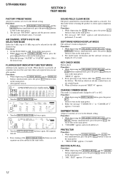
... TUNING MODE button, press the power ?/1 button to turn on the main power. 2. Turn the INPUT SELECTOR dial. The model name, destination and the software version are not counted again. 3. Every pressing of repair. The buttons which are already counted once are displayed. (10 second) KEY CHECK MODE Button check Procedure: 1. buttons simultaneously, press the power ?/1 button to turn on the main power. 2. STR-K880/K900 SECTION 2 TEST MODE FACTORY PRESET MODE All preset contents are reset to the default setting...
... TUNING MODE button, press the power ?/1 button to turn on the main power. 2. Turn the INPUT SELECTOR dial. The model name, destination and the software version are not counted again. 3. Every pressing of repair. The buttons which are already counted once are displayed. (10 second) KEY CHECK MODE Button check Procedure: 1. buttons simultaneously, press the power ?/1 button to turn on the main power. 2. STR-K880/K900 SECTION 2 TEST MODE FACTORY PRESET MODE All preset contents are reset to the default setting...

Service Manual
Page 13
... the power ?/1 button to start , below display will show: "DCAC[][][]x" x = 1, 2, 3, 4 If there is error happen, below display will change while displayed.) DCAC FACTORY TEST MODE DCAC Factory Test mode have two stages: 1. While depressing the TUNING MODE and the MUSIC buttons simultaneously, press the power ?/1 button to 255 (depends on the main power. 2. DCAC DSP Data Line Checking 2. "DCAC[]FTM" appears. Turn MASTER VOLUME jog, there will be test tone sound output from front left speaker of test tone) STR-K880/K900 13...
... the power ?/1 button to start , below display will show: "DCAC[][][]x" x = 1, 2, 3, 4 If there is error happen, below display will change while displayed.) DCAC FACTORY TEST MODE DCAC Factory Test mode have two stages: 1. While depressing the TUNING MODE and the MUSIC buttons simultaneously, press the power ?/1 button to 255 (depends on the main power. 2. DCAC DSP Data Line Checking 2. "DCAC[]FTM" appears. Turn MASTER VOLUME jog, there will be test tone sound output from front left speaker of test tone) STR-K880/K900 13...
Service Manual
Page 14
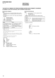
... side which enables seeing. Replace only with a VOM (Input impedance 10 MΩ). Ne les remplacer que par une piéce portant le numéro spécifié. • A : B+ Line. • B : B- F : FM J : ANALOG c : DIGITAL I : VIDEO • Abbreviation AUS : Australian model. CND : Canadian model. STR-K880/K900 Ver. 1.1 SECTION 3 DIAGRAMS THIS NOTE IS COMMON FOR PRINTED WIRING BOARDS AND SCHEMATIC DIAGRAMS. (In addition to...
... side which enables seeing. Replace only with a VOM (Input impedance 10 MΩ). Ne les remplacer que par une piéce portant le numéro spécifié. • A : B+ Line. • B : B- F : FM J : ANALOG c : DIGITAL I : VIDEO • Abbreviation AUS : Australian model. CND : Canadian model. STR-K880/K900 Ver. 1.1 SECTION 3 DIAGRAMS THIS NOTE IS COMMON FOR PRINTED WIRING BOARDS AND SCHEMATIC DIAGRAMS. (In addition to...

Service Manual
Page 16
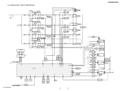
... VIDEO AMP V.OUT 15 5 V2 3 DVD VCC 16 9 V3 VEE 8 16 IC807 +5V REG IC804 -5V REG J201(2/2) VIDEO OUT MONITOR J200(2/2) VIDEO OUT VIDEO 1 + V - V J404 (2/2) AUDIO OUT VIDEO 1 J402 (2/2) OUT MD/TAPE L • R-CH is omitted due to same as L-CH. • Signal Path : FM : ANALOG : DIGITAL : VIDEO SL DISPLAY A /POWER SECTION (Page 17) C SBL IC402 WOOFER AMP 5 7 J309 AUDIO OUT SUB WOOFER Q560 RELAY DRIVE RY560 MUTE TUNED STEREO SLATCH T.SERIAL CLK TUNER...
... VIDEO AMP V.OUT 15 5 V2 3 DVD VCC 16 9 V3 VEE 8 16 IC807 +5V REG IC804 -5V REG J201(2/2) VIDEO OUT MONITOR J200(2/2) VIDEO OUT VIDEO 1 + V - V J404 (2/2) AUDIO OUT VIDEO 1 J402 (2/2) OUT MD/TAPE L • R-CH is omitted due to same as L-CH. • Signal Path : FM : ANALOG : DIGITAL : VIDEO SL DISPLAY A /POWER SECTION (Page 17) C SBL IC402 WOOFER AMP 5 7 J309 AUDIO OUT SUB WOOFER Q560 RELAY DRIVE RY560 MUTE TUNED STEREO SLATCH T.SERIAL CLK TUNER...
Service Manual
Page 17
... C SURROUND SPEAKERS IMPEDANCE USE 6-16Ω FRONT B CENTER FL101 -20V D1110 D1108 D1107 D1111 55 62 66 69 68 67 56 58 S100 ?/1 SB SURROUND BACK K880 BRIGEABLE RY 72 FUSE DETECT 63 SIRCS 54 AVCC 35 VCC3 84 VCC5 23 RSTX 77 STOP 48 IC102 REMOTE 1 CONTROL RECEIVER IC1111 1 RESET 2 +B -B IC691 2 1 POWER AMP -B IC691 5 7 +3.3V +2.5V +5V TUNER +3.3V AEP, UK TUNER +10V RELAY +B AUDIO...
... C SURROUND SPEAKERS IMPEDANCE USE 6-16Ω FRONT B CENTER FL101 -20V D1110 D1108 D1107 D1111 55 62 66 69 68 67 56 58 S100 ?/1 SB SURROUND BACK K880 BRIGEABLE RY 72 FUSE DETECT 63 SIRCS 54 AVCC 35 VCC3 84 VCC5 23 RSTX 77 STOP 48 IC102 REMOTE 1 CONTROL RECEIVER IC1111 1 RESET 2 +B -B IC691 2 1 POWER AMP -B IC691 5 7 +3.3V +2.5V +5V TUNER +3.3V AEP, UK TUNER +10V RELAY +B AUDIO...

Service Manual
Page 25
...DIGITAL BOARD CNS501 (Page 19) E F G DIGITAL BOARD CNS502 (Page 19) G H I STR-K880/K900 ADCC BOARD CNP2000 (Page 35) I VIDEO 3 BOARD CN201 (Page 35) J SA-CD/CD IN R L MD/TAPE OUT R L IN R L DVD AUDIO IN R L VIDEO 2 AUDIO IN L R VIDEO 1 AUDIO OUT L R AUDIO IN L R FRONT R L MULTI CH IN SURROUND R L SUB WOOFER CENTER SUB WOOFER AUDIO OUT VIDEO BOARD CNP203 (Page 37) SPEAKER B BOARD CNP600 (Page 34) KL SURROUND TM601 SPEAKERS IMPEDANCE USE 6-16 Ω L R L FRONT A R SPEAKER...H-5 Q503 H-5 Q504 H-6 Q505 G-6 Q506 G-5 Ref. PRINTED WIRING BOARD -
...DIGITAL BOARD CNS501 (Page 19) E F G DIGITAL BOARD CNS502 (Page 19) G H I STR-K880/K900 ADCC BOARD CNP2000 (Page 35) I VIDEO 3 BOARD CN201 (Page 35) J SA-CD/CD IN R L MD/TAPE OUT R L IN R L DVD AUDIO IN R L VIDEO 2 AUDIO IN L R VIDEO 1 AUDIO OUT L R AUDIO IN L R FRONT R L MULTI CH IN SURROUND R L SUB WOOFER CENTER SUB WOOFER AUDIO OUT VIDEO BOARD CNP203 (Page 37) SPEAKER B BOARD CNP600 (Page 34) KL SURROUND TM601 SPEAKERS IMPEDANCE USE 6-16 Ω L R L FRONT A R SPEAKER...H-5 Q503 H-5 Q504 H-6 Q505 G-6 Q506 G-5 Ref. PRINTED WIRING BOARD -
Service Manual
Page 46
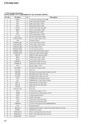
...I Audio data signal input from DIR I GP9 signal input from DSP O BST signal output to DSP O HCS signal output to DSP I Tone control input from rotary encoder. FL driver clock signal output terminal (not used) O FLASH2 signal output (not used) O FLASH1 signal output (not used 46 Ground terminal I Input Encoder (B) signal input - Tuning data output (not used ) I MODEL select input I Version setting input terminal (DESTINATION) - Analog ground terminal I ADCC signal input I Function key push signal input I Function key push signal input I Tone control input from...
...I Audio data signal input from DIR I GP9 signal input from DSP O BST signal output to DSP O HCS signal output to DSP I Tone control input from rotary encoder. FL driver clock signal output terminal (not used) O FLASH2 signal output (not used) O FLASH1 signal output (not used 46 Ground terminal I Input Encoder (B) signal input - Tuning data output (not used ) I MODEL select input I Version setting input terminal (DESTINATION) - Analog ground terminal I ADCC signal input I Function key push signal input I Function key push signal input I Tone control input from...
Service Manual
Page 47
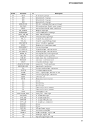
...output I Protector status detect signal input O Headphone relay control signal output I Fuse detect signal input I Volume signal input from rotary encoder I Volume signal input from rotary encoder O Front A speaker relay control signal output O Front B speaker control signal output O Center speaker relay control signal output O Rear speaker control signal output O Sub woofer control signal output O Analog switch IC clock signal output O Brigeable relay control output I Frequency data signal input from the tuner O Latch signal output to the tuner I Tuning a frequency signal input...
...output I Protector status detect signal input O Headphone relay control signal output I Fuse detect signal input I Volume signal input from rotary encoder I Volume signal input from rotary encoder O Front A speaker relay control signal output O Front B speaker control signal output O Center speaker relay control signal output O Rear speaker control signal output O Sub woofer control signal output O Analog switch IC clock signal output O Brigeable relay control output I Frequency data signal input from the tuner O Latch signal output to the tuner I Tuning a frequency signal input...

Service Manual
Page 52
...CONNECTOR (3.96mm PITCH) 3P < SWITCH > 0 S901 1-571-437-21 SWITCH, POWER VOLTAGE CHANGE (VOLTAGE SELECTOR) ADCC BOARD ...88 IC NJM4565D < JACK > J2000 1-820-056-11 SMALL TYPE JACK (AUTO CAL MIC) < RESISTOR >...model. STR-K880/K900 Ver. 1.1 AC SELECT ADCC DIGITAL NOTE: • Due to standardization, replacements in ohms. METAL: Metal-film resistor. Some delay should be different from the parts specified in the diagrams or the components used on the set. • -XX and -X mean standardized parts, so they are critical for routine service. E51 : Chilean and Peruvian models. Replace...
...CONNECTOR (3.96mm PITCH) 3P < SWITCH > 0 S901 1-571-437-21 SWITCH, POWER VOLTAGE CHANGE (VOLTAGE SELECTOR) ADCC BOARD ...88 IC NJM4565D < JACK > J2000 1-820-056-11 SMALL TYPE JACK (AUTO CAL MIC) < RESISTOR >...model. STR-K880/K900 Ver. 1.1 AC SELECT ADCC DIGITAL NOTE: • Due to standardization, replacements in ohms. METAL: Metal-film resistor. Some delay should be different from the parts specified in the diagrams or the components used on the set. • -XX and -X mean standardized parts, so they are critical for routine service. E51 : Chilean and Peruvian models. Replace...


