Operating Instructions
Page 3
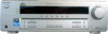
...Button Locations and Reference Pages Main unit 5 Hooking Up the Components Required cords 6 Antenna hookups 7 Audio component hookups 8 Video component hookups 9 Digital component hookups 10 Other hookups 11 Hooking Up and Setting Up the Speaker System Speaker system hookups ... Surround Sound Using only the front speakers (2 Channel Stereo 22 Enjoying higher fidelity sound 22 Selecting a sound field 23 Understanding the multi channel surround displays 25 Customizing sound fields 26 Receiving Broadcasts Storing FM stations automatically (AUTOBETICAL)1 28 Direct tuning 28 Automatic...
...Button Locations and Reference Pages Main unit 5 Hooking Up the Components Required cords 6 Antenna hookups 7 Audio component hookups 8 Video component hookups 9 Digital component hookups 10 Other hookups 11 Hooking Up and Setting Up the Speaker System Speaker system hookups ... Surround Sound Using only the front speakers (2 Channel Stereo 22 Enjoying higher fidelity sound 22 Selecting a sound field 23 Understanding the multi channel surround displays 25 Customizing sound fields 26 Receiving Broadcasts Storing FM stations automatically (AUTOBETICAL)1 28 Direct tuning 28 Automatic...
Operating Instructions
Page 5
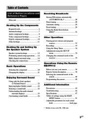
...indicator) qk (23, 24, 45) P - Illustration number r DISPLAY 2 (21, 31, 46) R R Name of buttons that are mentioned in the text. ws (30, 48) TUNER FM/AM q; (20, 29, 30, 33) TUNING +/- List of Button Locations and Reference Pages List of Button Locations and Reference Pages How to use this page...) CD 9 (20) DIMMER 3 (21) DISPLAY 2 (21, 31, 46) Display qa (21) DVD 7 (20) ENTER qg (33, 35) FM MODE wf (29) INPUT MODE qd (20) IR (receptor) 4 (36, 46) M - wd (29) VIDEO 1 5 (20) VIDEO 2 6 (20) NUMBERS AND SYMBOLS 2CH (button/indicator) wa (22, 24, 27) `/1 (power) 1 (14, 19, 27, 28, 35, 48...
...indicator) qk (23, 24, 45) P - Illustration number r DISPLAY 2 (21, 31, 46) R R Name of buttons that are mentioned in the text. ws (30, 48) TUNER FM/AM q; (20, 29, 30, 33) TUNING +/- List of Button Locations and Reference Pages List of Button Locations and Reference Pages How to use this page...) CD 9 (20) DIMMER 3 (21) DISPLAY 2 (21, 31, 46) Display qa (21) DVD 7 (20) ENTER qg (33, 35) FM MODE wf (29) INPUT MODE qd (20) IR (receptor) 4 (36, 46) M - wd (29) VIDEO 1 5 (20) VIDEO 2 6 (20) NUMBERS AND SYMBOLS 2CH (button/indicator) wa (22, 24, 27) `/1 (power) 1 (14, 19, 27, 28, 35, 48...
Operating Instructions
Page 6
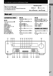
... (L/audio) Red (R/audio) D Optical digital cord (not supplied) E Coaxial digital cord (supplied) Orange C Video cord (not supplied) Yellow Before you hook up the components (pages 8 - 10). white (left, audio) to red. • When you connect optical digital cords, insert .... • Be sure to make connections firmly to avoid hum and noise. • When connecting an audio/video cord, be sure to match the color-coded pins to the appropriate jacks on the components: yellow (video) to yellow; E are required when you get started • Turn off the power to all components...
... (L/audio) Red (R/audio) D Optical digital cord (not supplied) E Coaxial digital cord (supplied) Orange C Video cord (not supplied) Yellow Before you hook up the components (pages 8 - 10). white (left, audio) to red. • When you connect optical digital cords, insert .... • Be sure to make connections firmly to avoid hum and noise. • When connecting an audio/video cord, be sure to match the color-coded pins to the appropriate jacks on the components: yellow (video) to yellow; E are required when you get started • Turn off the power to all components...
Operating Instructions
Page 7
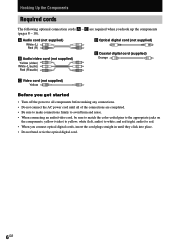
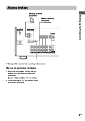
... area code. Hooking Up the Components Antenna hookups AM loop antenna (supplied) FM wire antenna (supplied) DIGITAL OPTICAL VIDEO 2 IN DVD IN COAXIAL ANTENNA AM y FM 75Ω COAXIAL MONITOR VIDEO IN VIDEO IN VIDEO OUT VIDEO IN VIDEO OUT L AUDIO OUT R IN CD OUT IN AUDIO IN AUDIO IN AUDIO... DVD VIDEO 2 VIDEO 1 WOOFER * * The shape of the connector varies depending on antenna hookups • To prevent noise pickup, keep the AM loop antenna away from the receiver and other components. • Be sure to fully extend the FM wire antenna. • After connecting the FM wire antenna...
... area code. Hooking Up the Components Antenna hookups AM loop antenna (supplied) FM wire antenna (supplied) DIGITAL OPTICAL VIDEO 2 IN DVD IN COAXIAL ANTENNA AM y FM 75Ω COAXIAL MONITOR VIDEO IN VIDEO IN VIDEO OUT VIDEO IN VIDEO OUT L AUDIO OUT R IN CD OUT IN AUDIO IN AUDIO IN AUDIO... DVD VIDEO 2 VIDEO 1 WOOFER * * The shape of the connector varies depending on antenna hookups • To prevent noise pickup, keep the AM loop antenna away from the receiver and other components. • Be sure to fully extend the FM wire antenna. • After connecting the FM wire antenna...
Operating Instructions
Page 8
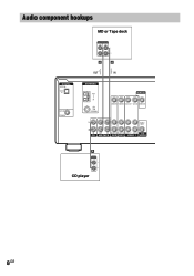
Audio component hookups DIGITAL OPTICAL VIDEO 2 IN DVD IN COAXIAL MD or Tape deck INPUT OUTPUT LINE LINE L R A A OUT IN ç ç ANTENNA AM y FM 75Ω COAXIAL MONITOR VIDEO IN VIDEO IN VIDEO OUT VIDEO IN VIDEO OUT L AUDIO OUT R IN CD OUT IN AUDIO IN AUDIO IN AUDIO OUT AUDIO IN SUB MD/TAPE DVD VIDEO 2 VIDEO 1 WOOFER A OUTPUT LINE L R CD player 8GB
Audio component hookups DIGITAL OPTICAL VIDEO 2 IN DVD IN COAXIAL MD or Tape deck INPUT OUTPUT LINE LINE L R A A OUT IN ç ç ANTENNA AM y FM 75Ω COAXIAL MONITOR VIDEO IN VIDEO IN VIDEO OUT VIDEO IN VIDEO OUT L AUDIO OUT R IN CD OUT IN AUDIO IN AUDIO IN AUDIO OUT AUDIO IN SUB MD/TAPE DVD VIDEO 2 VIDEO 1 WOOFER A OUTPUT LINE L R CD player 8GB
Operating Instructions
Page 9
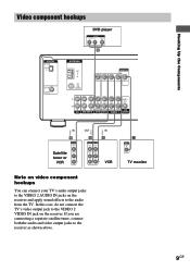
...from the TV. Hooking Up the Components Ç Ç Video component hookups DVD player OUTPUT AUDIO OUT R L VIDEO OUT B DIGITAL OPTICAL VIDEO 2 IN DVD IN COAXIAL ANTENNA AM y FM 75Ω COAXIAL MONITOR VIDEO IN VIDEO IN VIDEO OUT VIDEO IN VIDEO OUT L AUDIO OUT R IN CD OUT IN AUDIO IN...OUTPUT VIDEO VIDEO IN OUT AUDIO AUDIO IN OUT L R VCR C INPUT VIDEO IN TV monitor Note on video component hookups You can connect your TV's audio output jacks to the VIDEO 2 AUDIO IN jacks on the receiver. In this case, do not connect the TV's video output jack to the VIDEO 2 VIDEO IN ...
...from the TV. Hooking Up the Components Ç Ç Video component hookups DVD player OUTPUT AUDIO OUT R L VIDEO OUT B DIGITAL OPTICAL VIDEO 2 IN DVD IN COAXIAL ANTENNA AM y FM 75Ω COAXIAL MONITOR VIDEO IN VIDEO IN VIDEO OUT VIDEO IN VIDEO OUT L AUDIO OUT R IN CD OUT IN AUDIO IN...OUTPUT VIDEO VIDEO IN OUT AUDIO AUDIO IN OUT L R VCR C INPUT VIDEO IN TV monitor Note on video component hookups You can connect your TV's audio output jacks to the VIDEO 2 AUDIO IN jacks on the receiver. In this case, do not connect the TV's video output jack to the VIDEO 2 VIDEO IN ...
Operating Instructions
Page 10
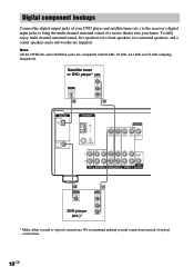
... jacks are required. Satellite tuner or DVD player* OUTPUT VIDEO OUT OUTPUT DIGITAL OPTICAL AUDIO OUT L R D B DIGITAL OPTICAL VIDEO 2 IN DVD IN COAXIAL ANTENNA AM y FM 75Ω COAXIAL MONITOR VIDEO IN VIDEO IN VIDEO OUT VIDEO IN VIDEO OUT L AUDIO OUT R IN CD OUT IN AUDIO IN...TAPE DVD VIDEO 2 VIDEO 1 WOOFER E OUTPUT DIGITAL COAXIAL DVD player (etc.)* B OUTPUT VIDEO OUT AUDIO OUT L R * Make either coaxial or optical connections. We recommend making coaxial connections instead of a movie theater into your DVD player and satellite tuner (etc.) to the receiver's digital ...
... jacks are required. Satellite tuner or DVD player* OUTPUT VIDEO OUT OUTPUT DIGITAL OPTICAL AUDIO OUT L R D B DIGITAL OPTICAL VIDEO 2 IN DVD IN COAXIAL ANTENNA AM y FM 75Ω COAXIAL MONITOR VIDEO IN VIDEO IN VIDEO OUT VIDEO IN VIDEO OUT L AUDIO OUT R IN CD OUT IN AUDIO IN...TAPE DVD VIDEO 2 VIDEO 1 WOOFER E OUTPUT DIGITAL COAXIAL DVD player (etc.)* B OUTPUT VIDEO OUT AUDIO OUT L R * Make either coaxial or optical connections. We recommend making coaxial connections instead of a movie theater into your DVD player and satellite tuner (etc.) to the receiver's digital ...

Operating Instructions
Page 11
... 12). VOLTAGE SELECTOR 120V 220V 240V Connecting the AC power cord Before connecting the AC power cord of your receiver has a voltage selector on the rear panel, check that the voltage selector is set the selector to the correct position before connecting the AC power ... AC power cord RL RL RL RL FRONT CENTER SURROUND SPEAKERS IMPEDANCE USE 8 - 16Ω b To a wall outlet Setting the voltage selector If your audio/ video components to a wall outlet. 11GB
... 12). VOLTAGE SELECTOR 120V 220V 240V Connecting the AC power cord Before connecting the AC power cord of your receiver has a voltage selector on the rear panel, check that the voltage selector is set the selector to the correct position before connecting the AC power ... AC power cord RL RL RL RL FRONT CENTER SURROUND SPEAKERS IMPEDANCE USE 8 - 16Ω b To a wall outlet Setting the voltage selector If your audio/ video components to a wall outlet. 11GB

Operating Instructions
Page 12
Hooking Up and Setting Up the Speaker System Speaker system hookups Required cords A Speaker cords (supplied) (+) (-) B Monaural audio cord (supplied) Black Active sub woofer INPUT Front speaker (R) Front speaker (L) e Ee E b B To a wall outlet (Switch the power (POWER) to off before connecting the power cord.) A A MONITOR VIDEO OUT AUDIO OUT SUB WOOFER RL RL RL RL FRONT CENTER SURROUND SPEAKERS IMPEDANCE USE 8 - 16Ω 12GB E A A A e Ee Ee Center speaker Surround speaker Surround speaker (R) (L)
Hooking Up and Setting Up the Speaker System Speaker system hookups Required cords A Speaker cords (supplied) (+) (-) B Monaural audio cord (supplied) Black Active sub woofer INPUT Front speaker (R) Front speaker (L) e Ee E b B To a wall outlet (Switch the power (POWER) to off before connecting the power cord.) A A MONITOR VIDEO OUT AUDIO OUT SUB WOOFER RL RL RL RL FRONT CENTER SURROUND SPEAKERS IMPEDANCE USE 8 - 16Ω 12GB E A A A e Ee Ee Center speaker Surround speaker Surround speaker (R) (L)
Operating Instructions
Page 20
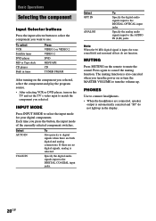
... digital audio signals input to the DIGITAL COAXIAL input jacks. MUTING Press MUTING on or turn the volume up in tuner Press VIDEO 1 or VIDEO 2 VIDEO 2 DVD MD/TAPE CD TUNER FM/AM After turning on the component you selected, select the component and play the program source. • After selecting VCR or DVD... player, turn on the TV and set the TV's video input to match the component you turn the power on the remote to cancel the...
... digital audio signals input to the DIGITAL COAXIAL input jacks. MUTING Press MUTING on or turn the volume up in tuner Press VIDEO 1 or VIDEO 2 VIDEO 2 DVD MD/TAPE CD TUNER FM/AM After turning on the component you selected, select the component and play the program source. • After selecting VCR or DVD... player, turn on the TV and set the TV's video input to match the component you turn the power on the remote to cancel the...
Operating Instructions
Page 23
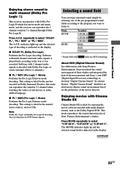
...Digital Cinema Sound" simulates an ideal movie theater sound environment based on the preference of old movies or in 5.1 channel when watching the videos of the movie director. Enjoying movies with Cinema Studio EX Cinema Studio EX is decoded with Dolby Pro Logic to the way it ..., Sony measured the sound environment of their studios and integrated the data of decoding is ideal for DTS format signals. Press MOVIE repeatedly to select "DOLBY PL", "PL MOV" or "PL MUS". Enjoying Surround Sound Enjoying stereo sound in multi channel (Dolby Pro Logic ) This receiver incorporates...
...Digital Cinema Sound" simulates an ideal movie theater sound environment based on the preference of old movies or in 5.1 channel when watching the videos of the movie director. Enjoying movies with Cinema Studio EX Cinema Studio EX is decoded with Dolby Pro Logic to the way it ..., Sony measured the sound environment of their studios and integrated the data of decoding is ideal for DTS format signals. Press MOVIE repeatedly to select "DOLBY PL", "PL MOV" or "PL MUS". Enjoying Surround Sound Enjoying stereo sound in multi channel (Dolby Pro Logic ) This receiver incorporates...

Operating Instructions
Page 34
... on the recording VCR, then start playback. Using the Sleep Timer You can also add audio from the original medium. Adjustments using the receiver. Initial settings Parameter DEC. The remaining time appears in the display. To resume audio recording from another audio source, select the program source...To check the remaining time before you want . You can set the receiver to be recorded onto the audio track of the video tape instead of the audio from a variety of audio sources when editing a video tape. See the operating instructions of your VCR or DVD player if you...
... on the recording VCR, then start playback. Using the Sleep Timer You can also add audio from the original medium. Adjustments using the receiver. Initial settings Parameter DEC. The remaining time appears in the display. To resume audio recording from another audio source, select the program source...To check the remaining time before you want . You can set the receiver to be recorded onto the audio track of the video tape instead of the audio from a variety of audio sources when editing a video tape. See the operating instructions of your VCR or DVD player if you...

Operating Instructions
Page 36
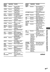
Tip Under normal conditions, the batteries should last for an extended period of each button. Remote Button ?/1 SLEEP Operations Function Receiver Receiver Turns the receiver on the receiver. When using the remote, point it at the remote sensor g on or off automatically. 36GB Notes • Do...MODE H X x TOP MENU/ GUIDE MUTING AV MENU F G g MASTER VOL f O DISPLAY TV VOL RETURN/EXIT TV/ MAIN TV CH VIDEO MENU WIDE ON SCREEN The tables below show the settings of time, remove the batteries to avoid possible damage from battery leakage and corrosion. Operations...
Tip Under normal conditions, the batteries should last for an extended period of each button. Remote Button ?/1 SLEEP Operations Function Receiver Receiver Turns the receiver on the receiver. When using the remote, point it at the remote sensor g on or off automatically. 36GB Notes • Do...MODE H X x TOP MENU/ GUIDE MUTING AV MENU F G g MASTER VOL f O DISPLAY TV VOL RETURN/EXIT TV/ MAIN TV CH VIDEO MENU WIDE ON SCREEN The tables below show the settings of time, remove the batteries to avoid possible damage from battery leakage and corrosion. Operations...
Operating Instructions
Page 37
... VCR. (VTR mode 2) To watch TV programs or satellite receiver. To listen to radio programs. To listen to select one of the receiver on or off the receiver STANDBY TV/VCR/ and other Sony audio/ (Press Satellite tuner/ video components. Remote Button Operations Function SHIFT Receiver Press repeatedly to select a memory page for presetting radio stations...
... VCR. (VTR mode 2) To watch TV programs or satellite receiver. To listen to radio programs. To listen to select one of the receiver on or off the receiver STANDBY TV/VCR/ and other Sony audio/ (Press Satellite tuner/ video components. Remote Button Operations Function SHIFT Receiver Press repeatedly to select a memory page for presetting radio stations...

Operating Instructions
Page 39
.../ VCR/ Press to the previous menu. TV Selects the channel entry mode, either one or two digit. TV VOL TV +/- TV/ TV VIDEO Selects input signal: TV input or video input. Remote Button Operations Function SEARCH MODE DVD player Select searching mode. AV MENU VCR/ Displays menu. DVD player TV ?/1 TV Turns...
.../ VCR/ Press to the previous menu. TV Selects the channel entry mode, either one or two digit. TV VOL TV +/- TV/ TV VIDEO Selects input signal: TV input or video input. Remote Button Operations Function SEARCH MODE DVD player Select searching mode. AV MENU VCR/ Displays menu. DVD player TV ?/1 TV Turns...
Operating Instructions
Page 41
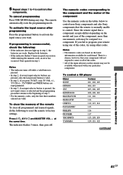
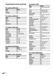
... pressed, only the last pressed button is valid. • In step 2, if you press TV ?/1, only TV VOL +/-, TV CH +/-, TV/VIDEO and WIDE buttons are reprogrammed. • In step 3, if an input selector button is pressed, the new input source is unsuccessful, check the following... exits the programming mode. Replace both batteries. • If the indicator flashes 4 times in the tables below to control non-Sony components and also Sony components that a component accepts differs depending on the latest information available for each brand. If you want. Since the remote signal ...
... pressed, only the last pressed button is valid. • In step 2, if you press TV ?/1, only TV VOL +/-, TV CH +/-, TV/VIDEO and WIDE buttons are reprogrammed. • In step 3, if an input selector button is pressed, the new input source is unsuccessful, check the following... exits the programming mode. Replace both batteries. • If the indicator flashes 4 times in the tables below to control non-Sony components and also Sony components that a component accepts differs depending on the latest information available for each brand. If you want. Since the remote signal ...
Operating Instructions
Page 42
...deck Maker SONY DENON KENWOOD NAKAMICHI PANASONIC PHILIPS PIONEER TECHNICS YAMAHA Code(s) 201, 202 204, 205 206, 207, 208, 209 210 216 211, 212 213, 214 215, 216 217, 218 To control an LD player Maker SONY PIONEER Code(s) 601, 602, 603 606 To control a video CD player Maker SONY Code(s) ...605 To control a VCR Maker SONY AIWA AKAI BLAUPUNKT EMERSON FISHER GENERAL ELECTRIC GOLDSTAR GRUNDIG HITACHI ITT/NOKIA JVC MAGNAVOX MITSUBISHI/...
...deck Maker SONY DENON KENWOOD NAKAMICHI PANASONIC PHILIPS PIONEER TECHNICS YAMAHA Code(s) 201, 202 204, 205 206, 207, 208, 209 210 216 211, 212 213, 214 215, 216 217, 218 To control an LD player Maker SONY PIONEER Code(s) 601, 602, 603 606 To control a video CD player Maker SONY Code(s) ...605 To control a VCR Maker SONY AIWA AKAI BLAUPUNKT EMERSON FISHER GENERAL ELECTRIC GOLDSTAR GRUNDIG HITACHI ITT/NOKIA JVC MAGNAVOX MITSUBISHI/...
Operating Instructions
Page 47
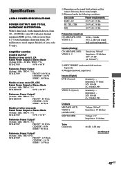
...VIDEO 1, 2 Sensitivity: 500 mV Impedance: 50 kilohms S/N3): 96 dB (A, 500 mV4)) 3) INPUT SHORT (with sound field and tone bypassed). 4) Weighted network, input level. Impedance: - Amplifier section POWER OUTPUT Models of area code U, CA Rated Power Output at Stereo Mode (8 ohms 40 Hz - 20 kHz, THD 0.7 %) STR-K750P...: 90 W + 90 W Reference Power Output (8 ohms 1 kHz, THD 0.7 %) STR-K750P: FRONT1):100 W/ch CENTER1): 100 W SURR1): 100 W/ch Models of...
...VIDEO 1, 2 Sensitivity: 500 mV Impedance: 50 kilohms S/N3): 96 dB (A, 500 mV4)) 3) INPUT SHORT (with sound field and tone bypassed). 4) Weighted network, input level. Impedance: - Amplifier section POWER OUTPUT Models of area code U, CA Rated Power Output at Stereo Mode (8 ohms 40 Hz - 20 kHz, THD 0.7 %) STR-K750P...: 90 W + 90 W Reference Power Output (8 ohms 1 kHz, THD 0.7 %) STR-K750P: FRONT1):100 W/ch CENTER1): 100 W SURR1): 100 W/ch Models of...
Operating Instructions
Page 48
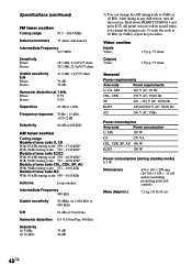
After tuning in any AM station, turn off the receiver. Video section Inputs Video: Outputs Video: 1 Vp-p, 75 ohms 1 Vp-p, 75 ohms General Power requirements Area code Power requirements U, CA, MX 120 V AC, 60 Hz CEL, CEK 230 V AC, 50/60 ...10 kHz (or 9 kHz), repeat the procedure. To reset the scale to 9 kHz or 10 kHz. Specifications (continued) FM tuner section Tuning range 87.5 - 108.0 MHz Antenna terminals 75 ohms, unbalanced Intermediate Frequency 10.7 MHz Sensitivity Mono: Stereo: 18.3 dBf, 2.2 µV/75 ohms 38.3 dBf, 22.5 µV/75 ohms Usable sensitivity S/N Mono...
After tuning in any AM station, turn off the receiver. Video section Inputs Video: Outputs Video: 1 Vp-p, 75 ohms 1 Vp-p, 75 ohms General Power requirements Area code Power requirements U, CA, MX 120 V AC, 60 Hz CEL, CEK 230 V AC, 50/60 ...10 kHz (or 9 kHz), repeat the procedure. To reset the scale to 9 kHz or 10 kHz. Specifications (continued) FM tuner section Tuning range 87.5 - 108.0 MHz Antenna terminals 75 ohms, unbalanced Intermediate Frequency 10.7 MHz Sensitivity Mono: Stereo: 18.3 dBf, 2.2 µV/75 ohms 38.3 dBf, 22.5 µV/75 ohms Usable sensitivity S/N Mono...


