
Limited Warranty (U.S. Only)
Page 1
...two (2) year. has established telephone numbers for frequently asked questions: To locate the servicer or dealer nearest you must be defective, Sony will supply, at no charge, new or rebuilt replacements in material or workmanship as fuses or batteries). EXCEPT TO THE EXTENT ... ANY EXPRESS OR IMPLIED WARRANTY ON THIS PRODUCT. 4-557-173-02 General Stereo/Hifi Components/Tape Decks ® CD Players/Mini Disc Players/Audio Systems Hifi Audio LIMITED WARRANTY Sony Electronics Inc. ("Sony") warrants this Product is valid only in Japan This warranty does not cover...
...two (2) year. has established telephone numbers for frequently asked questions: To locate the servicer or dealer nearest you must be defective, Sony will supply, at no charge, new or rebuilt replacements in material or workmanship as fuses or batteries). EXCEPT TO THE EXTENT ... ANY EXPRESS OR IMPLIED WARRANTY ON THIS PRODUCT. 4-557-173-02 General Stereo/Hifi Components/Tape Decks ® CD Players/Mini Disc Players/Audio Systems Hifi Audio LIMITED WARRANTY Sony Electronics Inc. ("Sony") warrants this Product is valid only in Japan This warranty does not cover...
Operating Instructions
Page 1
Refer to them whenever you call upon your Sony dealer regarding this product. HT-DDW750 © 2003 Sony Corporation Model No. Serial No. Record the serial number in the space provided below. 4-244-183-12(1) Home Theater System Operating Instructions Owner's Record The model and serial numbers are located at the rear of the unit.
Refer to them whenever you call upon your Sony dealer regarding this product. HT-DDW750 © 2003 Sony Corporation Model No. Serial No. Record the serial number in the space provided below. 4-244-183-12(1) Home Theater System Operating Instructions Owner's Record The model and serial numbers are located at the rear of the unit.
Operating Instructions
Page 2
...BE FULLY INSERTED TO PREVENT BLADE EXPOSURE. Reorient or relocate the receiving antenna. - Increase the separation between the equipment and receiver. - Except for help. As an ENERGY STAR® partner, Sony Corporation has determined that the cable ground shall be determined by... turning the equipment off and on a circuit different from Dolby Laboratories. This receiver incorporates Dolby* Digital and...
...BE FULLY INSERTED TO PREVENT BLADE EXPOSURE. Reorient or relocate the receiving antenna. - Increase the separation between the equipment and receiver. - Except for help. As an ENERGY STAR® partner, Sony Corporation has determined that the cable ground shall be determined by... turning the equipment off and on a circuit different from Dolby Laboratories. This receiver incorporates Dolby* Digital and...
Operating Instructions
Page 3
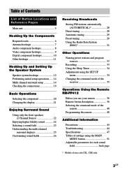
... 20 Changing the display 21 Enjoying Surround Sound Using only the front speakers (2 Channel Stereo 22 Enjoying higher fidelity sound 22 Selecting a sound field 23 Understanding the multi channel surround displays 25 Customizing sound fields 26 Receiving Broadcasts Storing FM stations automatically (AUTOBETICAL)1 28 Direct tuning 28 Automatic tuning 29 Preset tuning 29...
... 20 Changing the display 21 Enjoying Surround Sound Using only the front speakers (2 Channel Stereo 22 Enjoying higher fidelity sound 22 Selecting a sound field 23 Understanding the multi channel surround displays 25 Customizing sound fields 26 Receiving Broadcasts Storing FM stations automatically (AUTOBETICAL)1 28 Direct tuning 28 Automatic tuning 29 Preset tuning 29...
Operating Instructions
Page 4
... only SA-WMSP75 • Models of other area code SA-WMSP85 About area codes The area code of the receiver you purchased is shown on the lower portion of other area code STR-K750P - Tip The instructions in the text, for the supplied remote RM-PP412 The VIDEO3, TV/SAT, PHONO, AUX, MULTI... CH, SOURCE, DIRECT, AAC BI-LING, SB DECODING, 12 and ON SCREEN buttons on the remote are clearly indicated in this manual describe the controls on the receiver. About This...
... only SA-WMSP75 • Models of other area code SA-WMSP85 About area codes The area code of the receiver you purchased is shown on the lower portion of other area code STR-K750P - Tip The instructions in the text, for the supplied remote RM-PP412 The VIDEO3, TV/SAT, PHONO, AUX, MULTI... CH, SOURCE, DIRECT, AAC BI-LING, SB DECODING, 12 and ON SCREEN buttons on the remote are clearly indicated in this manual describe the controls on the receiver. About This...
Operating Instructions
Page 5
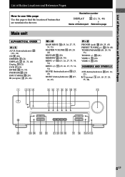
... (23, 24, 45) P - L A.F.D. (button/indicator) w; (22- 24) CD 9 (20) DIMMER 3 (21) DISPLAY 2 (21, 31, 46) Display qa (21) DVD 7 (20) ENTER qg (33, 35) FM MODE wf (29) INPUT MODE qd (20) IR (receptor) 4 (36, 46) M - Z PHONES (jack) wh (20, 25, 45) PRESET TUNING +/- wd (29) VIDEO 1 5 (20) VIDEO 2 6 (20...(20) MEMORY wg (28, 30) MENU +/- Illustration number r DISPLAY 2 (21, 31, 46) R R Name of buttons that are mentioned in the text. ws (30, 48) TUNER FM/AM q; (20, 29, 30, 33) TUNING +/- ql qk qj qh qgqf qd 5GB List of Button Locations and Reference Pages List of Button Locations and...
... (23, 24, 45) P - L A.F.D. (button/indicator) w; (22- 24) CD 9 (20) DIMMER 3 (21) DISPLAY 2 (21, 31, 46) Display qa (21) DVD 7 (20) ENTER qg (33, 35) FM MODE wf (29) INPUT MODE qd (20) IR (receptor) 4 (36, 46) M - Z PHONES (jack) wh (20, 25, 45) PRESET TUNING +/- wd (29) VIDEO 1 5 (20) VIDEO 2 6 (20...(20) MEMORY wg (28, 30) MENU +/- Illustration number r DISPLAY 2 (21, 31, 46) R R Name of buttons that are mentioned in the text. ws (30, 48) TUNER FM/AM q; (20, 29, 30, 33) TUNING +/- ql qk qj qh qgqf qd 5GB List of Button Locations and Reference Pages List of Button Locations and...
Operating Instructions
Page 6
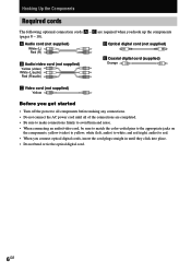
and red (right, audio) to red. • When you get started • Turn off the power to all of the connections are required when you hook up the components (pages 8 - 10). white (left, audio) to yellow; A Audio cord (not supplied) White (L) Red (R) B Audio/video cord (not supplied) Yellow (video) White (L/audio) Red (R/audio) D Optical digital cord (not supplied) E Coaxial digital cord (supplied) Orange C Video cord (not supplied) Yellow Before you connect optical digital cords, insert the cord plugs straight in until all components before making any connections. • Do ...
and red (right, audio) to red. • When you get started • Turn off the power to all of the connections are required when you hook up the components (pages 8 - 10). white (left, audio) to yellow; A Audio cord (not supplied) White (L) Red (R) B Audio/video cord (not supplied) Yellow (video) White (L/audio) Red (R/audio) D Optical digital cord (not supplied) E Coaxial digital cord (supplied) Orange C Video cord (not supplied) Yellow Before you connect optical digital cords, insert the cord plugs straight in until all components before making any connections. • Do ...
Operating Instructions
Page 7
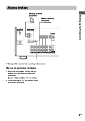
Hooking Up the Components Antenna hookups AM loop antenna (supplied) FM wire antenna (supplied) DIGITAL OPTICAL VIDEO 2 IN DVD IN COAXIAL ANTENNA AM y FM 75Ω COAXIAL MONITOR VIDEO IN VIDEO IN VIDEO OUT VIDEO IN VIDEO OUT L AUDIO OUT R IN CD OUT IN AUDIO IN AUDIO IN ... connector varies depending on antenna hookups • To prevent noise pickup, keep the AM loop antenna away from the receiver and other components. • Be sure to fully extend the FM wire antenna. • After connecting the FM wire antenna, keep it as horizontal as possible. 7GB Notes on the area code.
Hooking Up the Components Antenna hookups AM loop antenna (supplied) FM wire antenna (supplied) DIGITAL OPTICAL VIDEO 2 IN DVD IN COAXIAL ANTENNA AM y FM 75Ω COAXIAL MONITOR VIDEO IN VIDEO IN VIDEO OUT VIDEO IN VIDEO OUT L AUDIO OUT R IN CD OUT IN AUDIO IN AUDIO IN ... connector varies depending on antenna hookups • To prevent noise pickup, keep the AM loop antenna away from the receiver and other components. • Be sure to fully extend the FM wire antenna. • After connecting the FM wire antenna, keep it as horizontal as possible. 7GB Notes on the area code.
Operating Instructions
Page 8
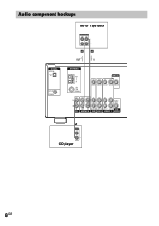
Audio component hookups DIGITAL OPTICAL VIDEO 2 IN DVD IN COAXIAL MD or Tape deck INPUT OUTPUT LINE LINE L R A A OUT IN ç ç ANTENNA AM y FM 75Ω COAXIAL MONITOR VIDEO IN VIDEO IN VIDEO OUT VIDEO IN VIDEO OUT L AUDIO OUT R IN CD OUT IN AUDIO IN AUDIO IN AUDIO OUT AUDIO IN SUB MD/TAPE DVD VIDEO 2 VIDEO 1 WOOFER A OUTPUT LINE L R CD player 8GB
Audio component hookups DIGITAL OPTICAL VIDEO 2 IN DVD IN COAXIAL MD or Tape deck INPUT OUTPUT LINE LINE L R A A OUT IN ç ç ANTENNA AM y FM 75Ω COAXIAL MONITOR VIDEO IN VIDEO IN VIDEO OUT VIDEO IN VIDEO OUT L AUDIO OUT R IN CD OUT IN AUDIO IN AUDIO IN AUDIO OUT AUDIO IN SUB MD/TAPE DVD VIDEO 2 VIDEO 1 WOOFER A OUTPUT LINE L R CD player 8GB
Operating Instructions
Page 9
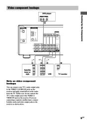
... Hooking Up the Components Ç Ç Video component hookups DVD player OUTPUT AUDIO OUT R L VIDEO OUT B DIGITAL OPTICAL VIDEO 2 IN DVD IN COAXIAL ANTENNA AM y FM 75Ω COAXIAL MONITOR VIDEO IN VIDEO IN VIDEO OUT VIDEO IN VIDEO OUT L AUDIO OUT R IN CD OUT IN AUDIO IN AUDIO IN AUDIO... on video component hookups You can connect your TV's audio output jacks to the VIDEO 2 AUDIO IN jacks on the receiver and apply sound effects to the VIDEO 2 VIDEO IN jack on the receiver. If you are connecting a separate satellite tuner, connect both the audio and video output jacks to the...
... Hooking Up the Components Ç Ç Video component hookups DVD player OUTPUT AUDIO OUT R L VIDEO OUT B DIGITAL OPTICAL VIDEO 2 IN DVD IN COAXIAL ANTENNA AM y FM 75Ω COAXIAL MONITOR VIDEO IN VIDEO IN VIDEO OUT VIDEO IN VIDEO OUT L AUDIO OUT R IN CD OUT IN AUDIO IN AUDIO IN AUDIO... on video component hookups You can connect your TV's audio output jacks to the VIDEO 2 AUDIO IN jacks on the receiver and apply sound effects to the VIDEO 2 VIDEO IN jack on the receiver. If you are connecting a separate satellite tuner, connect both the audio and video output jacks to the...
Operating Instructions
Page 10
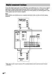
... tuner or DVD player* OUTPUT VIDEO OUT OUTPUT DIGITAL OPTICAL AUDIO OUT L R D B DIGITAL OPTICAL VIDEO 2 IN DVD IN COAXIAL ANTENNA AM y FM 75Ω COAXIAL MONITOR VIDEO IN VIDEO IN VIDEO OUT VIDEO IN VIDEO OUT L AUDIO OUT R IN CD OUT IN AUDIO IN AUDIO IN AUDIO...COAXIAL jacks are required. We recommend making coaxial connections instead of a movie theater into your DVD player and satellite tuner (etc.) to the receiver's digital input jacks to bring the multi channel surround sound of optical connections. 10GB To fully enjoy multi channel surround sound, five speakers (...
... tuner or DVD player* OUTPUT VIDEO OUT OUTPUT DIGITAL OPTICAL AUDIO OUT L R D B DIGITAL OPTICAL VIDEO 2 IN DVD IN COAXIAL ANTENNA AM y FM 75Ω COAXIAL MONITOR VIDEO IN VIDEO IN VIDEO OUT VIDEO IN VIDEO OUT L AUDIO OUT R IN CD OUT IN AUDIO IN AUDIO IN AUDIO...COAXIAL jacks are required. We recommend making coaxial connections instead of a movie theater into your DVD player and satellite tuner (etc.) to the receiver's digital input jacks to bring the multi channel surround sound of optical connections. 10GB To fully enjoy multi channel surround sound, five speakers (...

Operating Instructions
Page 11
... outlet Setting the voltage selector If your audio/ video components to a wall outlet. 11GB Connect the AC power cord(s) of this receiver to a wall outlet, connect the speaker system to the receiver (page 12). VOLTAGE SELECTOR 120V 220V 240V Connecting the AC power cord Before connecting the AC power cord of your... receiver has a voltage selector on the rear panel, check that the voltage selector is set the selector to the correct position before connecting the AC power...
... outlet Setting the voltage selector If your audio/ video components to a wall outlet. 11GB Connect the AC power cord(s) of this receiver to a wall outlet, connect the speaker system to the receiver (page 12). VOLTAGE SELECTOR 120V 220V 240V Connecting the AC power cord Before connecting the AC power cord of your... receiver has a voltage selector on the rear panel, check that the voltage selector is set the selector to the correct position before connecting the AC power...

Operating Instructions
Page 12
Hooking Up and Setting Up the Speaker System Speaker system hookups Required cords A Speaker cords (supplied) (+) (-) B Monaural audio cord (supplied) Black Active sub woofer INPUT Front speaker (R) Front speaker (L) e Ee E b B To a wall outlet (Switch the power (POWER) to off before connecting the power cord.) A A MONITOR VIDEO OUT AUDIO OUT SUB WOOFER RL RL RL RL FRONT CENTER SURROUND SPEAKERS IMPEDANCE USE 8 - 16Ω 12GB E A A A e Ee Ee Center speaker Surround speaker Surround speaker (R) (L)
Hooking Up and Setting Up the Speaker System Speaker system hookups Required cords A Speaker cords (supplied) (+) (-) B Monaural audio cord (supplied) Black Active sub woofer INPUT Front speaker (R) Front speaker (L) e Ee E b B To a wall outlet (Switch the power (POWER) to off before connecting the power cord.) A A MONITOR VIDEO OUT AUDIO OUT SUB WOOFER RL RL RL RL FRONT CENTER SURROUND SPEAKERS IMPEDANCE USE 8 - 16Ω 12GB E A A A e Ee Ee Center speaker Surround speaker Surround speaker (R) (L)

Operating Instructions
Page 13
...and center speaker terminals. • Twist the stripped ends of another speaker terminal. 13GB To avoid short-circuiting the speakers Short-circuiting of the receiver. Examples of poor conditions of the speaker cord Stripped cords are not fully attached and are reversed, the sound will lack bass. •... the Speaker System Tip To prevent speaker vibration or movement while listening, attach the supplied foot pads at the level you turn off the receiver. After connecting all the components, speakers, and AC power cord, output a test tone to check that you turn down the volume before...
...and center speaker terminals. • Twist the stripped ends of another speaker terminal. 13GB To avoid short-circuiting the speakers Short-circuiting of the receiver. Examples of poor conditions of the speaker cord Stripped cords are not fully attached and are reversed, the sound will lack bass. •... the Speaker System Tip To prevent speaker vibration or movement while listening, attach the supplied foot pads at the level you turn off the receiver. After connecting all the components, speakers, and AC power cord, output a test tone to check that you turn down the volume before...
Operating Instructions
Page 14
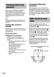
... sound, all speakers should be placed from 1.0 to 7.0 meters (3 to set to the listening position. However, we recommend that the receiver correspond to the side, depending on the shape of input selectors and preset stations. • The master volume is set up to ...23 feet) from the listening position (A). For the adjustable parameters, see the table on the power, clear the receiver's memory. Performing initial setup operations Before using your receiver for 5 seconds. You can be the same distance from the listening position (A). Performing initial setup operations Once ...
... sound, all speakers should be placed from 1.0 to 7.0 meters (3 to set to the listening position. However, we recommend that the receiver correspond to the side, depending on the shape of input selectors and preset stations. • The master volume is set up to ...23 feet) from the listening position (A). For the adjustable parameters, see the table on the power, clear the receiver's memory. Performing initial setup operations Before using your receiver for 5 seconds. You can be the same distance from the listening position (A). Performing initial setup operations Once ...
Operating Instructions
Page 15
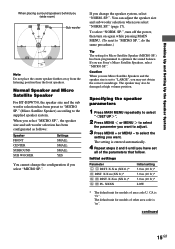
... SR PL. The default unit for Micro Satellite Speaker (MICRO SP.) has been programmed to "LARGE", you select "MICRO SP.". continued 15GB When you use Sony's Micro Satellite Speakers, select "MICRO SP.". Caution When you select "MICRO SP.", the speaker size and sub woofer selection has been configurated as follows: Speaker...
... SR PL. The default unit for Micro Satellite Speaker (MICRO SP.) has been programmed to "LARGE", you select "MICRO SP.". continued 15GB When you use Sony's Micro Satellite Speakers, select "MICRO SP.". Caution When you select "MICRO SP.", the speaker size and sub woofer selection has been configurated as follows: Speaker...
Operating Instructions
Page 16
... speaker distance ( C DIST. Center speaker distance should be set to your surround speakers for proper implementation of the Digital Cinema Sound surround modes. Tip The receiver allows you specify the height of the sound from your listening position to the center speaker. Also, the center speaker cannot be set the center...
... speaker distance ( C DIST. Center speaker distance should be set to your surround speakers for proper implementation of the Digital Cinema Sound surround modes. Tip The receiver allows you specify the height of the sound from your listening position to the center speaker. Also, the center speaker cannot be set the center...

Operating Instructions
Page 17
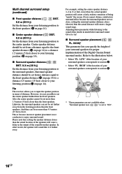
For details on your listening environment. However, if the front speakers are set to "SMALL", you cannot set the center speaker to "LARGE". • If the sound is set to "NO", the front speakers are also automatically set to "SMALL" (unless previously set to obtain proper balance. The sound of the Digital Cinema Sound modes with virtual elements. Choose the setting that provides a good sense of the front speakers. All modes with virtual elements were designed under the premise that best succeeds in forming a cohesive space between the surround sound from the surround ...
For details on your listening environment. However, if the front speakers are set to "SMALL", you cannot set the center speaker to "LARGE". • If the sound is set to "NO", the front speakers are also automatically set to "SMALL" (unless previously set to obtain proper balance. The sound of the Digital Cinema Sound modes with virtual elements. Choose the setting that provides a good sense of the front speakers. All modes with virtual elements were designed under the premise that best succeeds in forming a cohesive space between the surround sound from the surround ...
Operating Instructions
Page 18
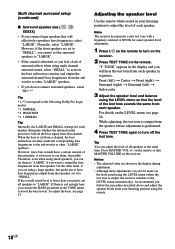
...lack of surround effects when using small speakers, you can use the BASS parameter in the TONE menu to turn MASTER VOLUME on the receiver. Therefore, even when using multi channel surround sound, select "SMALL" to activate the bass redirection circuitry and output the surround channel ...8226; If you do not connect surround speakers, select "NO".*3 Tip *1-*3 correspond to the following Dolby Pro Logic modes *1 NORMAL *2 PHANTOM *3 3 STEREO Tip Internally, the LARGE and SMALL settings for easier speaker level adjustment. 1 Press ?/1 on the remote to adjust the level of the test tone sounds...
...lack of surround effects when using small speakers, you can use the BASS parameter in the TONE menu to turn MASTER VOLUME on the receiver. Therefore, even when using multi channel surround sound, select "SMALL" to activate the bass redirection circuitry and output the surround channel ...8226; If you do not connect surround speakers, select "NO".*3 Tip *1-*3 correspond to the following Dolby Pro Logic modes *1 NORMAL *2 PHANTOM *3 3 STEREO Tip Internally, the LARGE and SMALL settings for easier speaker level adjustment. 1 Press ?/1 on the remote to adjust the level of the test tone sounds...
Operating Instructions
Page 19
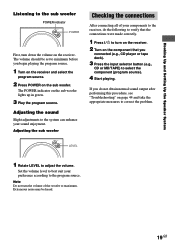
... level to best suit your preference according to the system can enhance your components to the receiver, do not obtain normal sound output after performing this procedure, see "Troubleshooting" on the receiver. Adjusting the sound Slight adjustments to the program source. LEVEL 1 Rotate LEVEL to turn on... the receiver. 2 Turn on the component that you begin playing the program source. 1 Turn on the receiver and select the program source. 2 Press POWER on the sub woofer lights up in green. 3 Play...
... level to best suit your preference according to the system can enhance your components to the receiver, do not obtain normal sound output after performing this procedure, see "Troubleshooting" on the receiver. Adjusting the sound Slight adjustments to the program source. LEVEL 1 Rotate LEVEL to turn on... the receiver. 2 Turn on the component that you begin playing the program source. 1 Turn on the receiver and select the program source. 2 Press POWER on the sub woofer lights up in green. 3 Play...
