
Limited Warranty (U.S. Only)
Page 1
...in exchange for defective parts for all parts costs. 3. 4-557-173-02 General Stereo/Hifi Components/Tape Decks ® CD Players/Mini Disc Players/Audio Systems Hifi Audio LIMITED WARRANTY Sony Electronics Inc. ("Sony") warrants this Product is determined to be presented to obtain warranty service. LABOR: ...incidental or consequential damages, or allow limitations on how long an implied warranty lasts does not apply to you must be defective, Sony will supply, at its original packaging or packaging affording an equal degree of protection, to any part of purchase in material ...
...in exchange for defective parts for all parts costs. 3. 4-557-173-02 General Stereo/Hifi Components/Tape Decks ® CD Players/Mini Disc Players/Audio Systems Hifi Audio LIMITED WARRANTY Sony Electronics Inc. ("Sony") warrants this Product is determined to be presented to obtain warranty service. LABOR: ...incidental or consequential damages, or allow limitations on how long an implied warranty lasts does not apply to you must be defective, Sony will supply, at its original packaging or packaging affording an equal degree of protection, to any part of purchase in material ...
Operating Instructions (HT-DDW650)
Page 1
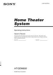
Model No. HT-DDW650 © 2003 Sony Corporation 4-244-183-71(1) Home Theater System Operating Instructions Owner's Record The model and serial numbers are located at the rear of the unit. Serial No. Refer to them whenever you call upon your Sony dealer regarding this product. Record the serial number in the space provided below.
Model No. HT-DDW650 © 2003 Sony Corporation 4-244-183-71(1) Home Theater System Operating Instructions Owner's Record The model and serial numbers are located at the rear of the unit. Serial No. Refer to them whenever you call upon your Sony dealer regarding this product. Record the serial number in the space provided below.
Operating Instructions (HT-DDW650)
Page 2
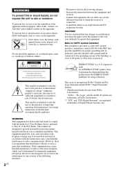
...on the apparatus. If this product meets the ENERGY STAR® guidelines for help. ENERGY STAR® is connected. - This receiver incorporates Dolby* Digital and Pro Logic Surround and the DTS** Digital Surround System. * Manufactured under license from that may cause harmful... trademarks of Digital Theater Systems, Inc. As an ENERGY STAR® partner, Sony Corporation has determined that this equipment does cause harmful interference to radio or television reception, which the receiver is a U.S. Connect the equipment into an outlet on the apparatus. WARNING To...
...on the apparatus. If this product meets the ENERGY STAR® guidelines for help. ENERGY STAR® is connected. - This receiver incorporates Dolby* Digital and Pro Logic Surround and the DTS** Digital Surround System. * Manufactured under license from that may cause harmful... trademarks of Digital Theater Systems, Inc. As an ENERGY STAR® partner, Sony Corporation has determined that this equipment does cause harmful interference to radio or television reception, which the receiver is a U.S. Connect the equipment into an outlet on the apparatus. WARNING To...
Operating Instructions (HT-DDW650)
Page 3
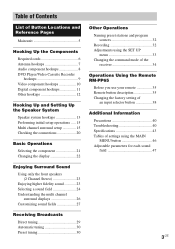
...display 22 Enjoying Surround Sound Using only the front speakers (2 Channel Stereo 23 Enjoying higher fidelity sound 23 Selecting a sound field 24 Understanding the multi channel surround displays 26 Customizing sound fields 27 Receiving Broadcasts Direct tuning 29 Automatic tuning 30 Preset tuning 30 Other Operations...Naming preset stations and program sources 32 Recording 32 Adjustments using the SET UP menu 33 Changing the command mode of the receiver 34 Operations Using the Remote RM-PP65 Before you use your remote 35 Remote button description 35 Changing the factory setting ...
...display 22 Enjoying Surround Sound Using only the front speakers (2 Channel Stereo 23 Enjoying higher fidelity sound 23 Selecting a sound field 24 Understanding the multi channel surround displays 26 Customizing sound fields 27 Receiving Broadcasts Direct tuning 29 Automatic tuning 30 Preset tuning 30 Other Operations...Naming preset stations and program sources 32 Recording 32 Adjustments using the SET UP menu 33 Changing the command mode of the receiver 34 Operations Using the Remote RM-PP65 Before you use your remote 35 Remote button description 35 Changing the factory setting ...
Operating Instructions (HT-DDW650)
Page 4
About This Manual The HT-DDW650 consists of your remote, see pages 35 - 39. Note for the supplied remote For RM-PP65 The >10/11 and 12 buttons on the receiver. Speaker system • Front/surround speakers SS-MSP75 • Center speaker SS-CNP75 • Sub woofer SA-WMSP85 Tip The instructions in this manual describe the controls on the remote are not available. 4US You can also use the controls on the supplied remote if they have the same or similar names as those on the use of : - For details on the receiver. Receiver STR-K650P -
About This Manual The HT-DDW650 consists of your remote, see pages 35 - 39. Note for the supplied remote For RM-PP65 The >10/11 and 12 buttons on the receiver. Speaker system • Front/surround speakers SS-MSP75 • Center speaker SS-CNP75 • Sub woofer SA-WMSP85 Tip The instructions in this manual describe the controls on the remote are not available. 4US You can also use the controls on the supplied remote if they have the same or similar names as those on the use of : - For details on the receiver. Receiver STR-K650P -
Operating Instructions (HT-DDW650)
Page 5
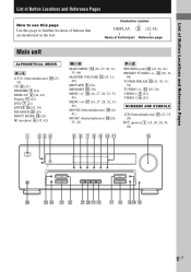
... (16, 27, 28, 32, 33, 46) MOVIE (button/indicator) ql (24, 41) MUSIC (button/indicator) qk (24, 25, 41) 5 6 7 8 9 0 qa P - ws (30, 31, 44) TUNER FM/AM q; (21, 30, 31, 32) TUNING +/- wd (29, 30) VIDEO 1 5 (21) VIDEO 2 6 (21) NUMBERS AND SYMBOLS 2CH (button/indicator) wa (23, 25, 28) `/1 (power) 1 (15... page Main unit ALPHABETICAL ORDER A - L A.F.D. (button/indicator) w; (23- 25) CD 9 (21) DIMMER 3 (22) DISPLAY 2 (22, 42) Display qa (22) DVD 7 (21) ENTER qg (32, 34) FM MODE wf (29) INPUT MODE qd (21) IR (receptor) 4 (35, 42) 1 23 4 M - ql qk qj qh qgqf qd 5US
... (16, 27, 28, 32, 33, 46) MOVIE (button/indicator) ql (24, 41) MUSIC (button/indicator) qk (24, 25, 41) 5 6 7 8 9 0 qa P - ws (30, 31, 44) TUNER FM/AM q; (21, 30, 31, 32) TUNING +/- wd (29, 30) VIDEO 1 5 (21) VIDEO 2 6 (21) NUMBERS AND SYMBOLS 2CH (button/indicator) wa (23, 25, 28) `/1 (power) 1 (15... page Main unit ALPHABETICAL ORDER A - L A.F.D. (button/indicator) w; (23- 25) CD 9 (21) DIMMER 3 (22) DISPLAY 2 (22, 42) Display qa (22) DVD 7 (21) ENTER qg (32, 34) FM MODE wf (29) INPUT MODE qd (21) IR (receptor) 4 (35, 42) 1 23 4 M - ql qk qj qh qgqf qd 5US
Operating Instructions (HT-DDW650)
Page 6
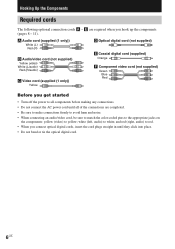
white (left, audio) to yellow; and red (right, audio) to all of the connections are required when you connect optical digital cords, insert the cord plugs straight in until all components before making any connections. • Do not connect the AC power cord until they click into place. • Do not bend or tie the optical digital cord. 6US A Audio cord (supplied (1 only)) White (L) Red (R) B Audio/video cord (not supplied) Yellow (video) White (L/audio) Red (R/audio) C Video cord (supplied (1 only)) Yellow D Optical digital cord (not supplied) E Coaxial digital cord (...
white (left, audio) to yellow; and red (right, audio) to all of the connections are required when you connect optical digital cords, insert the cord plugs straight in until all components before making any connections. • Do not connect the AC power cord until they click into place. • Do not bend or tie the optical digital cord. 6US A Audio cord (supplied (1 only)) White (L) Red (R) B Audio/video cord (not supplied) Yellow (video) White (L/audio) Red (R/audio) C Video cord (supplied (1 only)) Yellow D Optical digital cord (not supplied) E Coaxial digital cord (...
Operating Instructions (HT-DDW650)
Page 7
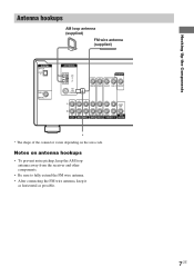
Hooking Up the Components Antenna hookups AM loop antenna (supplied) FM wire antenna (supplied) DIGITAL OPTICAL VIDEO 2 IN DVD IN COAXIAL ANTENNA AM y FM 75Ω COAXIAL MONITOR VIDEO IN VIDEO IN VIDEO OUT VIDEO IN VIDEO OUT L AUDIO OUT R IN CD OUT IN AUDIO IN AUDIO IN ... connector varies depending on antenna hookups • To prevent noise pickup, keep the AM loop antenna away from the receiver and other components. • Be sure to fully extend the FM wire antenna. • After connecting the FM wire antenna, keep it as horizontal as possible. 7US Notes on the area code.
Hooking Up the Components Antenna hookups AM loop antenna (supplied) FM wire antenna (supplied) DIGITAL OPTICAL VIDEO 2 IN DVD IN COAXIAL ANTENNA AM y FM 75Ω COAXIAL MONITOR VIDEO IN VIDEO IN VIDEO OUT VIDEO IN VIDEO OUT L AUDIO OUT R IN CD OUT IN AUDIO IN AUDIO IN ... connector varies depending on antenna hookups • To prevent noise pickup, keep the AM loop antenna away from the receiver and other components. • Be sure to fully extend the FM wire antenna. • After connecting the FM wire antenna, keep it as horizontal as possible. 7US Notes on the area code.
Operating Instructions (HT-DDW650)
Page 8
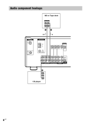
Audio component hookups DIGITAL OPTICAL VIDEO 2 IN DVD IN COAXIAL MD or Tape deck INPUT OUTPUT LINE LINE L R A A OUT IN ç ç ANTENNA AM y FM 75Ω COAXIAL MONITOR VIDEO IN VIDEO IN VIDEO OUT VIDEO IN VIDEO OUT L AUDIO OUT R IN CD OUT IN AUDIO IN AUDIO IN AUDIO OUT AUDIO IN SUB MD/TAPE DVD VIDEO 2 VIDEO 1 WOOFER A OUTPUT LINE L R CD player 8US
Audio component hookups DIGITAL OPTICAL VIDEO 2 IN DVD IN COAXIAL MD or Tape deck INPUT OUTPUT LINE LINE L R A A OUT IN ç ç ANTENNA AM y FM 75Ω COAXIAL MONITOR VIDEO IN VIDEO IN VIDEO OUT VIDEO IN VIDEO OUT L AUDIO OUT R IN CD OUT IN AUDIO IN AUDIO IN AUDIO OUT AUDIO IN SUB MD/TAPE DVD VIDEO 2 VIDEO 1 WOOFER A OUTPUT LINE L R CD player 8US
Operating Instructions (HT-DDW650)
Page 9
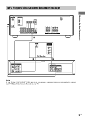
Hooking Up the Components DVD Player/Video Cassette Recorder hookups DIGITAL OPTICAL VIDEO 2 IN E DVD IN COAXIAL ANTENNA AM y FM 75Ω COAXIAL MONITOR VIDEO IN VIDEO IN VIDEO OUT VIDEO IN VIDEO OUT L AUDIO OUT R IN CD OUT IN AUDIO IN AUDIO IN AUDIO ...
Hooking Up the Components DVD Player/Video Cassette Recorder hookups DIGITAL OPTICAL VIDEO 2 IN E DVD IN COAXIAL ANTENNA AM y FM 75Ω COAXIAL MONITOR VIDEO IN VIDEO IN VIDEO OUT VIDEO IN VIDEO OUT L AUDIO OUT R IN CD OUT IN AUDIO IN AUDIO IN AUDIO ...
Operating Instructions (HT-DDW650)
Page 10
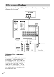
... connecting a separate satellite tuner, connect both the audio and video output jacks to the receiver as shown below. DVD player OUTPUT AUDIO OUT R L VIDEO OUT B DIGITAL OPTICAL VIDEO 2 IN DVD IN COAXIAL ANTENNA AM y FM 75Ω COAXIAL MONITOR VIDEO IN VIDEO IN VIDEO OUT VIDEO IN VIDEO OUT L...this case, do not connect the TV's video output jack to the VIDEO 2 VIDEO IN jack on the receiver and apply sound effects to the VIDEO 2 AUDIO IN jacks on the receiver. C INPUT VIDEO IN TV monitor 10US Video component hookups If you can connect your video components as shown ...
... connecting a separate satellite tuner, connect both the audio and video output jacks to the receiver as shown below. DVD player OUTPUT AUDIO OUT R L VIDEO OUT B DIGITAL OPTICAL VIDEO 2 IN DVD IN COAXIAL ANTENNA AM y FM 75Ω COAXIAL MONITOR VIDEO IN VIDEO IN VIDEO OUT VIDEO IN VIDEO OUT L...this case, do not connect the TV's video output jack to the VIDEO 2 VIDEO IN jack on the receiver and apply sound effects to the VIDEO 2 AUDIO IN jacks on the receiver. C INPUT VIDEO IN TV monitor 10US Video component hookups If you can connect your video components as shown ...
Operating Instructions (HT-DDW650)
Page 11
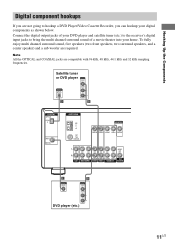
.... Satellite tuner or DVD player OUTPUT VIDEO OUT OUTPUT DIGITAL OPTICAL AUDIO OUT L R D B DIGITAL OPTICAL VIDEO 2 IN DVD IN COAXIAL ANTENNA AM y FM 75Ω COAXIAL MONITOR VIDEO IN VIDEO IN VIDEO OUT VIDEO IN VIDEO OUT L AUDIO OUT R IN CD OUT IN AUDIO IN AUDIO IN AUDIO... Note All the OPTICAL and COAXIAL jacks are required. Connect the digital output jacks of your DVD player and satellite tuner (etc.) to the receiver's digital input jacks to hookup a DVD Player/Video Cassette Recorder, you can hookup your home. Hooking Up the Components Digital component hookups If you...
.... Satellite tuner or DVD player OUTPUT VIDEO OUT OUTPUT DIGITAL OPTICAL AUDIO OUT L R D B DIGITAL OPTICAL VIDEO 2 IN DVD IN COAXIAL ANTENNA AM y FM 75Ω COAXIAL MONITOR VIDEO IN VIDEO IN VIDEO OUT VIDEO IN VIDEO OUT L AUDIO OUT R IN CD OUT IN AUDIO IN AUDIO IN AUDIO... Note All the OPTICAL and COAXIAL jacks are required. Connect the digital output jacks of your DVD player and satellite tuner (etc.) to the receiver's digital input jacks to hookup a DVD Player/Video Cassette Recorder, you can hookup your home. Hooking Up the Components Digital component hookups If you...
Operating Instructions (HT-DDW650)
Page 12
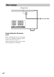
Connect the AC power cord(s) of this receiver to a wall outlet, connect the speaker system to a wall outlet. b To a wall outlet 12US Other hookups AC power cord RL RL RL RL FRONT CENTER SURROUND SPEAKERS IMPEDANCE USE 8 - 16Ω Connecting the AC power cord Before connecting the AC power cord of your audio/ video components to the receiver (page 13).
Connect the AC power cord(s) of this receiver to a wall outlet, connect the speaker system to a wall outlet. b To a wall outlet 12US Other hookups AC power cord RL RL RL RL FRONT CENTER SURROUND SPEAKERS IMPEDANCE USE 8 - 16Ω Connecting the AC power cord Before connecting the AC power cord of your audio/ video components to the receiver (page 13).
Operating Instructions (HT-DDW650)
Page 13
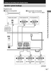
Hooking Up and Setting Up the Speaker System Hooking Up and Setting Up the Speaker System Speaker system hookups Required cords A Speaker cords (supplied) (+) (-) B Monaural audio cord (supplied) Black Active sub woofer INPUT AUDIO IN Front speaker (R) Front speaker (L) e Ee E b B To a wall outlet (Switch the power (POWER) to off before connecting the power cord.) A A MONITOR VIDEO OUT AUDIO OUT SUB WOOFER RL RL RL RL FRONT CENTER SURROUND SPEAKERS IMPEDANCE USE 8 - 16Ω E A A A e Ee Ee Center speaker Surround speaker Surround speaker (R) (L) continued ...
Hooking Up and Setting Up the Speaker System Hooking Up and Setting Up the Speaker System Speaker system hookups Required cords A Speaker cords (supplied) (+) (-) B Monaural audio cord (supplied) Black Active sub woofer INPUT AUDIO IN Front speaker (R) Front speaker (L) e Ee E b B To a wall outlet (Switch the power (POWER) to off before connecting the power cord.) A A MONITOR VIDEO OUT AUDIO OUT SUB WOOFER RL RL RL RL FRONT CENTER SURROUND SPEAKERS IMPEDANCE USE 8 - 16Ω E A A A e Ee Ee Center speaker Surround speaker Surround speaker (R) (L) continued ...
Operating Instructions (HT-DDW650)
Page 14
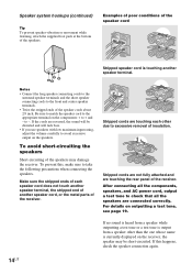
... -. Speaker system hookups (continued) Tip To prevent speaker vibration or movement while listening, attach the supplied foot pads at the bottom of the receiver. To prevent this happens, check the speaker connection again. 14US Stripped cords are not fully attached and are touching each speaker cord does not ...speakers. Make sure the stripped ends of each other than the one whose name is touching another speaker cord, or the metal parts of the receiver. If no sound is heard from a speaker while outputting a test tone or a test tone is output from a speaker other due to ...
... -. Speaker system hookups (continued) Tip To prevent speaker vibration or movement while listening, attach the supplied foot pads at the bottom of the receiver. To prevent this happens, check the speaker connection again. 14US Stripped cords are not fully attached and are touching each speaker cord does not ...speakers. Make sure the stripped ends of each other than the one whose name is touching another speaker cord, or the metal parts of the receiver. If no sound is heard from a speaker while outputting a test tone or a test tone is output from a speaker other due to ...
Operating Instructions (HT-DDW650)
Page 15
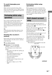
... preset stations. • All index names of your room (etc.). For the adjustable parameters, see the table on the power, clear the receiver's memory. When placing surround speakers to your system. Hooking Up and Setting Up the Speaker System To avoid damaging your speakers Make sure that ... sound, all speakers should be placed from the listening position (A). Tip To check the audio output during settings (to set to clear the receiver's memory, do the following are reset to their factory settings. • All settings in the display. Performing initial setup operations Before using ...
... preset stations. • All index names of your room (etc.). For the adjustable parameters, see the table on the power, clear the receiver's memory. When placing surround speakers to your system. Hooking Up and Setting Up the Speaker System To avoid damaging your speakers Make sure that ... sound, all speakers should be placed from the listening position (A). Tip To check the audio output during settings (to set to clear the receiver's memory, do the following are reset to their factory settings. • All settings in the display. Performing initial setup operations Before using ...
Operating Instructions (HT-DDW650)
Page 16
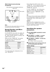
... DIST. You can adjust the speaker size and sub woofer selection when you may also be damaged at high volume position. Caution When you use Sony's Micro Satellite Speakers, select "MICRO SP.". XX ft. XX ft. When you select "MICRO SP.", the speaker size and sub woofer selection has been configurated...
... DIST. You can adjust the speaker size and sub woofer selection when you may also be damaged at high volume position. Caution When you use Sony's Micro Satellite Speakers, select "MICRO SP.". XX ft. XX ft. When you select "MICRO SP.", the speaker size and sub woofer selection has been configurated...
Operating Instructions (HT-DDW650)
Page 17
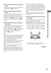
... speakers for proper implementation of being "inside" the screen. Center speaker distance should be set the center speaker further than the front speakers. Tip The receiver allows you cannot obtain a satisfactory surround effect because the surround speakers are not available when "Surround speaker size ( SL SR )" is not possible to set...
... speakers for proper implementation of being "inside" the screen. Center speaker distance should be set the center speaker further than the front speakers. Tip The receiver allows you cannot obtain a satisfactory surround effect because the surround speakers are not available when "Surround speaker size ( SL SR )" is not possible to set...
Operating Instructions (HT-DDW650)
Page 18
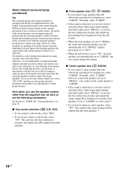
With the Digital Cinema Sound modes, speaker placement is distorted, or you feel a lack of the front speakers. LOW" and then use the speaker system other than the supplied one, be output from the front speakers (if set to "LARGE") or sub woofer.*1 • If you do not connect a sub woofer, select "NO". This activates the bass redirection circuitry and outputs the LFE signals from the surround speakers and the sound of surround effects when using multi channel surround sound, select "SMALL" to activate the bass redirection circuitry and output the center channel bass ...
With the Digital Cinema Sound modes, speaker placement is distorted, or you feel a lack of the front speakers. LOW" and then use the speaker system other than the supplied one, be output from the front speakers (if set to "LARGE") or sub woofer.*1 • If you do not connect a sub woofer, select "NO". This activates the bass redirection circuitry and outputs the LFE signals from the surround speakers and the sound of surround effects when using multi channel surround sound, select "SMALL" to activate the bass redirection circuitry and output the center channel bass ...
Operating Instructions (HT-DDW650)
Page 19
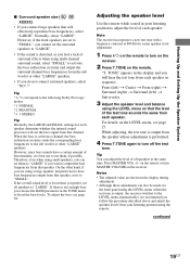
... speakers, you can adjust the level of each speaker in the TONE menu to turn off the test tone. When the bass is output, the receiver switches to "LARGE". To adjust the bass, see page 27. Front (left) t Center t Front (right) t Surround (right) t Surround (...your listening position to the following Dolby Pro Logic modes *1 NORMAL *2 PHANTOM *3 3 STEREO Tip Internally, the LARGE and SMALL settings for easier speaker level adjustment. 1 Press ?/1 on the remote. Note The receiver incorporates a new test tone with a frequency centered at the same time. Normally, select ...
... speakers, you can adjust the level of each speaker in the TONE menu to turn off the test tone. When the bass is output, the receiver switches to "LARGE". To adjust the bass, see page 27. Front (left) t Center t Front (right) t Surround (right) t Surround (...your listening position to the following Dolby Pro Logic modes *1 NORMAL *2 PHANTOM *3 3 STEREO Tip Internally, the LARGE and SMALL settings for easier speaker level adjustment. 1 Press ?/1 on the remote. Note The receiver incorporates a new test tone with a frequency centered at the same time. Normally, select ...