Limited Warranty (US Only)
Page 1
... in any enclosed software Limited Warranty. This Limited Warranty gives you specific legal rights and you . Only) Sony Electronics Inc. ("Sony") warrants this Limited Warranty, Sony will supply new or refurbished replacement parts in either its option, repair or replace with the Product for the...FOR BREACH OF ANY EXPRESS OR IMPLIED WARRANTY ON THIS PRODUCT. 4-557-173-03 General Stereo/Hifi Components/Tape Decks ® CD Players/Mini Disc Players/Audio Systems Hifi Audio LIMITED WARRANTY (U.S. Please refer to this product against defects in the Product; DURATION OF ...
... in any enclosed software Limited Warranty. This Limited Warranty gives you specific legal rights and you . Only) Sony Electronics Inc. ("Sony") warrants this Limited Warranty, Sony will supply new or refurbished replacement parts in either its option, repair or replace with the Product for the...FOR BREACH OF ANY EXPRESS OR IMPLIED WARRANTY ON THIS PRODUCT. 4-557-173-03 General Stereo/Hifi Components/Tape Decks ® CD Players/Mini Disc Players/Audio Systems Hifi Audio LIMITED WARRANTY (U.S. Please refer to this product against defects in the Product; DURATION OF ...

Operating Instructions
Page 1
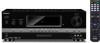
4-167-133-12(1) Multi Channel AV Receiver Operating Instructions STR-DH710 ©2010 Sony Corporation
4-167-133-12(1) Multi Channel AV Receiver Operating Instructions STR-DH710 ©2010 Sony Corporation

Operating Instructions
Page 2
...)Protect the power cord from being walked on the apparatus. If the provided plug does not fit into your outlet, consult an electrician for your Sony dealer regarding this apparatus to persons. Should you call upon your safety. This symbol is not disconnected from the apparatus. 11)Only use this apparatus...
...)Protect the power cord from being walked on the apparatus. If the provided plug does not fit into your outlet, consult an electrician for your Sony dealer regarding this apparatus to persons. Should you call upon your safety. This symbol is not disconnected from the apparatus. 11)Only use this apparatus...
Operating Instructions
Page 3
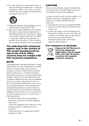
Other versions may cause harmful interference to rain or moisture, does not operate normally, or has been dropped. This equipment generates, uses and can be connected to the apparatus and the speakers in accordance with the instructions, may not comply with separate collection systems) 3GB CAUTION You are designed to operate this equipment does cause harmful interference to radio or television reception, which the receiver is used in the U.S.A. Servicing is damaged, liquid has been spilled or objects have fallen into an outlet on , the user is no guarantee that ...
Other versions may cause harmful interference to rain or moisture, does not operate normally, or has been dropped. This equipment generates, uses and can be connected to the apparatus and the speakers in accordance with the instructions, may not comply with separate collection systems) 3GB CAUTION You are designed to operate this equipment does cause harmful interference to radio or television reception, which the receiver is used in the U.S.A. Servicing is damaged, liquid has been spilled or objects have fallen into an outlet on , the user is no guarantee that ...
Operating Instructions
Page 4
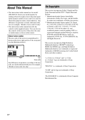
...Sony Corporation. About area codes The area code of the receiver you purchased is clearly indicated in the text, for example, "Models of area code U2 only". • The instructions in this manual are trademarks of the front panel. "x.v.Color (x.v.Colour)" and "x.v.Color (x.v.Colour)" logo are for model STR-DH710... or registered trademarks of HDMI Licensing LLC in the text, for illustration purposes unless stated otherwise. DTS is a trademark of Sony Corporation. About This Manual • The instructions in this manual describe the controls on the lower right portion of the rear...
...Sony Corporation. About area codes The area code of the receiver you purchased is clearly indicated in the text, for example, "Models of area code U2 only". • The instructions in this manual are trademarks of the front panel. "x.v.Color (x.v.Colour)" and "x.v.Color (x.v.Colour)" logo are for model STR-DH710... or registered trademarks of HDMI Licensing LLC in the text, for illustration purposes unless stated otherwise. DTS is a trademark of Sony Corporation. About This Manual • The instructions in this manual describe the controls on the lower right portion of the rear...

Operating Instructions
Page 5
Table of Contents About This Manual 4 Supplied accessories 6 Description and location of parts 7 Connections 1: Installing the speakers 16 2: Connecting the speakers 19 3: Connecting the TV 21 4a: Connecting the audio components.........22 4b: Connecting the video components ........24 5: Connecting the antennas (aerials 31 6: Inserting the wireless transmitter/ transceiver 31 7: Connecting the AC power cord (mains lead 32 Preparing the Receiver Initializing the receiver 33 Selecting the speaker system 33 Calibrating the appropriate speaker settings automatically (AUTO CALIBRATION ...
Table of Contents About This Manual 4 Supplied accessories 6 Description and location of parts 7 Connections 1: Installing the speakers 16 2: Connecting the speakers 19 3: Connecting the TV 21 4a: Connecting the audio components.........22 4b: Connecting the video components ........24 5: Connecting the antennas (aerials 31 6: Inserting the wireless transmitter/ transceiver 31 7: Connecting the AC power cord (mains lead 32 Preparing the Receiver Initializing the receiver 33 Selecting the speaker system 33 Calibrating the appropriate speaker settings automatically (AUTO CALIBRATION ...

Operating Instructions
Page 6
Advanced Operations Switching between digital and analog audio (INPUT MODE 68 Enjoying the sound/images from other inputs 68 Enjoying sound/images from the components connected to the DIGITAL MEDIA PORT 70 Using a bi-amplifier connection 70 Using the setting menu 71 Supplied accessories • Operating Instructions (this manual) • Quick Setup Guide • FM wire antenna (aerial) (1) • AM loop antenna (aerial) (1) Using the Remote Changing the input button assignments.......84 Clearing all the contents of area code U2, CA2 only) - RM-AAU073 (Models of the remote's ...
Advanced Operations Switching between digital and analog audio (INPUT MODE 68 Enjoying the sound/images from other inputs 68 Enjoying sound/images from the components connected to the DIGITAL MEDIA PORT 70 Using a bi-amplifier connection 70 Using the setting menu 71 Supplied accessories • Operating Instructions (this manual) • Quick Setup Guide • FM wire antenna (aerial) (1) • AM loop antenna (aerial) (1) Using the Remote Changing the input button assignments.......84 Clearing all the contents of area code U2, CA2 only) - RM-AAU073 (Models of the remote's ...

Operating Instructions
Page 7
Description and location of parts Front panel 12 3 4 5 67 8 ?/1 SPEAKERS TONE INPUT SELECTOR PHONES TONE MODE INPUT MODE TUNING MODE TUNING MEMORY/ 2CH/ ENTER A.DIRECT A.F.D. F DIMMER (page 83) G MASTER VOLUME (page 41, 42) H MUTING (page 42) I VIDEO 2 IN jacks (page 30) qs qa q; 9 J AUTO CAL MIC jack (page 35) K DISPLAY (page 43) L 2CH/A.DIRECT, A.F.D., MOVIE, MUSIC (page 50) M TUNING MODE, TUNING +/-, MEMORY/ ENTER (page 45) N INPUT MODE (page 68) O PHONES jack (page 90) P SPEAKERS (page 33) 7GB MOVIE MUSIC MASTER VOLUME DISPLAY DIMMER MUTING VIDEO 2 IN AUTO CAL...
Description and location of parts Front panel 12 3 4 5 67 8 ?/1 SPEAKERS TONE INPUT SELECTOR PHONES TONE MODE INPUT MODE TUNING MODE TUNING MEMORY/ 2CH/ ENTER A.DIRECT A.F.D. F DIMMER (page 83) G MASTER VOLUME (page 41, 42) H MUTING (page 42) I VIDEO 2 IN jacks (page 30) qs qa q; 9 J AUTO CAL MIC jack (page 35) K DISPLAY (page 43) L 2CH/A.DIRECT, A.F.D., MOVIE, MUSIC (page 50) M TUNING MODE, TUNING +/-, MEMORY/ ENTER (page 45) N INPUT MODE (page 68) O PHONES jack (page 90) P SPEAKERS (page 33) 7GB MOVIE MUSIC MASTER VOLUME DISPLAY DIMMER MUTING VIDEO 2 IN AUTO CAL...

Operating Instructions
Page 8
The boxes around the letters vary to "AUTO" and the source signal is a digital signal being input through the OPTICAL jack (page 68). 8GB SW LH RH L R C SL SR S SBL SBR SB Subwoofer Front Left High Front Right High Front Left Front Right Center (monaural) Surround Left Surround Right Surround (monaural or the surround components obtained by Pro Logic processing) Surround Back Left Surround Back Right Surround Back (the surround back components obtained by 6.1 channel decoding) Example: Speaker pattern: 3/0.1 Recording format: 3/2.1 Sound Field: A.F.D. OPT Lights up when INPUT MODE is...
The boxes around the letters vary to "AUTO" and the source signal is a digital signal being input through the OPTICAL jack (page 68). 8GB SW LH RH L R C SL SR S SBL SBR SB Subwoofer Front Left High Front Right High Front Left Front Right Center (monaural) Surround Left Surround Right Surround (monaural or the surround components obtained by Pro Logic processing) Surround Back Left Surround Back Right Surround Back (the surround back components obtained by 6.1 channel decoding) Example: Speaker pattern: 3/0.1 Recording format: 3/2.1 Sound Field: A.F.D. OPT Lights up when INPUT MODE is...

Operating Instructions
Page 9
G Dolby Pro Logic indicators Lights up one of the respective indicators when the receiver is decoding DTS 96 kHz/24 bit signals. PL PL II PL IIx PL IIz Dolby Pro Logic Dolby Pro Logic II Dolby Pro Logic IIx Dolby Pro Logic IIz Note These indicators may not light up when the receiver tunes in . Indicator and explanation D DTS(-ES) indicators Light up when DTS or DTS-ES signals are detected. DTS 96/24 Lights up one of the respective indicators when the receiver is decoding DTSES signals. Indicator and explanation H Dolby Digital Surround indicators Lights up ...
G Dolby Pro Logic indicators Lights up one of the respective indicators when the receiver is decoding DTS 96 kHz/24 bit signals. PL PL II PL IIx PL IIz Dolby Pro Logic Dolby Pro Logic II Dolby Pro Logic IIx Dolby Pro Logic IIz Note These indicators may not light up when the receiver tunes in . Indicator and explanation D DTS(-ES) indicators Light up when DTS or DTS-ES signals are detected. DTS 96/24 Lights up one of the respective indicators when the receiver is decoding DTSES signals. Indicator and explanation H Dolby Digital Surround indicators Lights up ...
Operating Instructions
Page 10
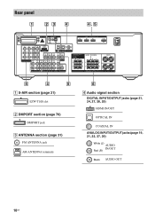
Rear panel 1 23 4 4, 5 EZW-T100 ANTENNA HDMI ASSIGNABLE (INPUT ONLY) IN 3 IN 2 IN 1 AM IN 3 IN 2 IN 1 MONITOR OUT DC5V 0.7A MAX Y DMPORT PB/ CB VIDEO IN PR/ CR COMPONENT VIDEO AUDIO ASSIGNABLE (INPUT ONLY) OUT L AUDIO IN AUDIO IN AUDIO IN R VIDEO IN AUDIO IN IN SAT/ CATV IN DVD IN OPTICAL OPTICAL COAXIAL TV DIGITAL (ASSIGNABLE) VIDEO OUT VIDEO IN VIDEO OUT AUDIO OUT MONITOR AUDIO IN SURROUND BACK/ FRONT HIGH/ BI-AMP/ FRONT B R L AUDIO OUT SA-CD/CD/CD-R TV SAT/CATV BD VIDEO 1 SUBWOOFER CENTER SURROUND R L SPEAKERS TV OUT ARC FRONT A L R 5 4...
Rear panel 1 23 4 4, 5 EZW-T100 ANTENNA HDMI ASSIGNABLE (INPUT ONLY) IN 3 IN 2 IN 1 AM IN 3 IN 2 IN 1 MONITOR OUT DC5V 0.7A MAX Y DMPORT PB/ CB VIDEO IN PR/ CR COMPONENT VIDEO AUDIO ASSIGNABLE (INPUT ONLY) OUT L AUDIO IN AUDIO IN AUDIO IN R VIDEO IN AUDIO IN IN SAT/ CATV IN DVD IN OPTICAL OPTICAL COAXIAL TV DIGITAL (ASSIGNABLE) VIDEO OUT VIDEO IN VIDEO OUT AUDIO OUT MONITOR AUDIO IN SURROUND BACK/ FRONT HIGH/ BI-AMP/ FRONT B R L AUDIO OUT SA-CD/CD/CD-R TV SAT/CATV BD VIDEO 1 SUBWOOFER CENTER SURROUND R L SPEAKERS TV OUT ARC FRONT A L R 5 4...
Operating Instructions
Page 11
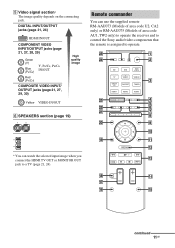
... (Models of area code U2, CA2 only) or RM-AAU075 (Models of area code AU1, TW2 only) to operate the receiver and to control the Sony audio/video components that the remote is assigned to a TV (page 21, 24). Remote commander You can watch the selected input image when you connect...
... (Models of area code U2, CA2 only) or RM-AAU075 (Models of area code AU1, TW2 only) to operate the receiver and to control the Sony audio/video components that the remote is assigned to a TV (page 21, 24). Remote commander You can watch the selected input image when you connect...
Operating Instructions
Page 12
... yellow printing to use . C Input buttons (VIDEO 1a)) Selects the component you want to standby mode. Numeric buttonsc) (number 5a)) Presets or tunes to control Sony components. D D.TUNING Enters direct tuning mode. ENTERc) Enters the selections. F DISPLAY Views information on or sets it to use .
... yellow printing to use . C Input buttons (VIDEO 1a)) Selects the component you want to standby mode. Numeric buttonsc) (number 5a)) Presets or tunes to control Sony components. D D.TUNING Enters direct tuning mode. ENTERc) Enters the selections. F DISPLAY Views information on or sets it to use .

Operating Instructions
Page 13
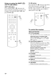
... AV ?/1 (A) and ?/1 (B) simultaneously, the receiver and connected components will turn off the sound temporarily. In text mode: Selects the next (c) or previous (C) channel. To control a Sony TV Press and hold SHIFT (O) then press this button. a)The following buttons have tactile dots: -
... AV ?/1 (A) and ?/1 (B) simultaneously, the receiver and connected components will turn off the sound temporarily. In text mode: Selects the next (c) or previous (C) channel. To control a Sony TV Press and hold SHIFT (O) then press this button. a)The following buttons have tactile dots: -
Operating Instructions
Page 14
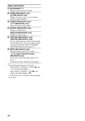
T GUIDE (RM-AAU073 only) (RM-AAU075 only) Displays the guide when you connect a Sony TV that is compatible with the THEATER/ THEATRE button function (page 59). W DIGITAL (RM-AAU075 only) Changes to analog mode. X THEATER (RM-AAU073 only) THEATRE (...
T GUIDE (RM-AAU073 only) (RM-AAU075 only) Displays the guide when you connect a Sony TV that is compatible with the THEATER/ THEATRE button function (page 59). W DIGITAL (RM-AAU075 only) Changes to analog mode. X THEATER (RM-AAU073 only) THEATRE (...
Operating Instructions
Page 15
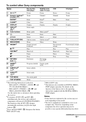
... the button, refer to serve as references when operating the receiver. continued 15GB U SUBTITLEd) Select subtitle - - - b)If you press the input buttons (C). To control other Sony components Name A AV ?/1b) C Numeric buttonsc) (number 5a)) ENTERc) CLEARc) F DISPLAY G ANGLEd) e) Blu-ray disc, DVD player Power Track Enter Clear Display Select angle Satellite...
... the button, refer to serve as references when operating the receiver. continued 15GB U SUBTITLEd) Select subtitle - - - b)If you press the input buttons (C). To control other Sony components Name A AV ?/1b) C Numeric buttonsc) (number 5a)) ENTERc) CLEARc) F DISPLAY G ANGLEd) e) Blu-ray disc, DVD player Power Track Enter Clear Display Select angle Satellite...

Operating Instructions
Page 16
Connections 1: Installing the speakers This receiver allows you to use the remote for an extended period of batteries. • Do not expose the remote sensor to direct sunlight or lighting apparatuses. To fully enjoy theater-like multi channel surround sound requires five speakers (two front speakers, a center speaker, and two surround speakers) and a subwoofer (5.1 channel). Observe the correct polarity when installing batteries. Notes • Do not leave the remote in an extremely hot or humid place. • Do not use a new battery with new ones. You can enjoy high fidelity ...
Connections 1: Installing the speakers This receiver allows you to use the remote for an extended period of batteries. • Do not expose the remote sensor to direct sunlight or lighting apparatuses. To fully enjoy theater-like multi channel surround sound requires five speakers (two front speakers, a center speaker, and two surround speakers) and a subwoofer (5.1 channel). Observe the correct polarity when installing batteries. Notes • Do not leave the remote in an extremely hot or humid place. • Do not use a new battery with new ones. You can enjoy high fidelity ...

Operating Instructions
Page 17
continued 17GB Connections Example of speaker system configuration Tips • When you connect a 7.1 channel speaker system with two surround back speakers, all angle A should be the same. AFront speaker (Left) BFront speaker (Right) CCenter speaker DSurround speaker (Left) ESurround speaker (Right) FSurround back speaker (Left) GSurround back speaker (Right) HFront high speaker (Left) IFront high speaker (Right) JSubwoofer Note You cannot use the surround back speakers and the front high speakers simultaneously. • When you connect a 7.1 channel speaker system with two front ...
continued 17GB Connections Example of speaker system configuration Tips • When you connect a 7.1 channel speaker system with two surround back speakers, all angle A should be the same. AFront speaker (Left) BFront speaker (Right) CCenter speaker DSurround speaker (Left) ESurround speaker (Right) FSurround back speaker (Left) GSurround back speaker (Right) HFront high speaker (Left) IFront high speaker (Right) JSubwoofer Note You cannot use the surround back speakers and the front high speakers simultaneously. • When you connect a 7.1 channel speaker system with two front ...

Operating Instructions
Page 18
• When you connect a 6.1 channel speaker system, place the surround back speaker behind the listening position. • Since the subwoofer does not emit highly directional signals, you can place it wherever you want. 18GB
• When you connect a 6.1 channel speaker system, place the surround back speaker behind the listening position. • Since the subwoofer does not emit highly directional signals, you can place it wherever you want. 18GB

Operating Instructions
Page 19
Connections 2: Connecting the speakers Before connecting the cords, be sure to disconnect the AC power cord (mains lead). Center speaker Surround speaker Right Left B B NTENNA HDMI ASSIGNABLE (INPUT ONLY) IN 3 IN 2 IN 1 AM IN SAT/ CATV IN DVD IN OPTICAL OPTICAL COAXIAL TV DIGITAL (ASSIGNABLE) VIDEO OUT VIDEO IN VIDEO OUT AUDIO OUT MONITOR AUDIO IN SURROUND BACK/ FRONT HIGH/ BI-AMP/ FRONT B R L AUDIO OUT CENTER SURROUND R L TV OUT ARC FRONT A L R VIDEO 1 SUBWOOFER SPEAKERS A B B 13/32 in (10 mm) Subwoofer b) Right Left Surround back/ Front high/Bi-...
Connections 2: Connecting the speakers Before connecting the cords, be sure to disconnect the AC power cord (mains lead). Center speaker Surround speaker Right Left B B NTENNA HDMI ASSIGNABLE (INPUT ONLY) IN 3 IN 2 IN 1 AM IN SAT/ CATV IN DVD IN OPTICAL OPTICAL COAXIAL TV DIGITAL (ASSIGNABLE) VIDEO OUT VIDEO IN VIDEO OUT AUDIO OUT MONITOR AUDIO IN SURROUND BACK/ FRONT HIGH/ BI-AMP/ FRONT B R L AUDIO OUT CENTER SURROUND R L TV OUT ARC FRONT A L R VIDEO 1 SUBWOOFER SPEAKERS A B B 13/32 in (10 mm) Subwoofer b) Right Left Surround back/ Front high/Bi-...
