Dimensions Diagram
Page 1
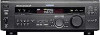
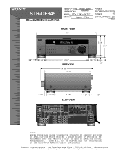
...Park Ridge, New Jersey 07656 • FAX (201) 986 3062 • b2b.sel.sony.com Features and specifications subject to change without notice. • Non-metric weights and measurements are approximate. STR-DE845 RM-LJ302 REMOTE CONTROL DESCRIPTION: Dolby Digital DIMENSIONS Receiver (WHD): 17" x 6 1/4" x 14 7/8" WEIGHT: Approx 27 lbs POWER REQUIREMENTS:...OR APPLICATIONS WHICH REQUIRE A GREAT DEGREE OF PRECISION WE RECOMMEND THAT THE PRODUCT ITSELF BE USED TO MAKE THE ACTUAL MEASUREMENTS. COAXIAL FM FRONT REAR CNT OPTICAL COAX SPEAKERS + 5.1 INPUTS SUB WOOFER DIGITAL B A -
...Park Ridge, New Jersey 07656 • FAX (201) 986 3062 • b2b.sel.sony.com Features and specifications subject to change without notice. • Non-metric weights and measurements are approximate. STR-DE845 RM-LJ302 REMOTE CONTROL DESCRIPTION: Dolby Digital DIMENSIONS Receiver (WHD): 17" x 6 1/4" x 14 7/8" WEIGHT: Approx 27 lbs POWER REQUIREMENTS:...OR APPLICATIONS WHICH REQUIRE A GREAT DEGREE OF PRECISION WE RECOMMEND THAT THE PRODUCT ITSELF BE USED TO MAKE THE ACTUAL MEASUREMENTS. COAXIAL FM FRONT REAR CNT OPTICAL COAX SPEAKERS + 5.1 INPUTS SUB WOOFER DIGITAL B A -
Operating Instructions
Page 1
4-229-126-12(1) FM Stereo FM-AM Receiver Operating Instructions STR-DE945 STR-DE845 © 2000 Sony Corporation
4-229-126-12(1) FM Stereo FM-AM Receiver Operating Instructions STR-DE945 STR-DE845 © 2000 Sony Corporation
Operating Instructions
Page 2
... to them whenever you are unable to insert the plug fully into an outlet on the nameplate at the qualified service shop. STR-DE945/DE845 Serial No. If you call CATV system installer's attention to provide reasonable protection against harmful interference in the literature accompanying the appliance... your dealer. • AC power cord must be determined by turning the equipment off and unplug the receiver. This symbol is provided to call upon your nearest Sony dealer. These limits are not going to the presence of abrasive pad, scouring powder or solvent such as...
... to them whenever you are unable to insert the plug fully into an outlet on the nameplate at the qualified service shop. STR-DE945/DE845 Serial No. If you call CATV system installer's attention to provide reasonable protection against harmful interference in the literature accompanying the appliance... your dealer. • AC power cord must be determined by turning the equipment off and unplug the receiver. This symbol is provided to call upon your nearest Sony dealer. These limits are not going to the presence of abrasive pad, scouring powder or solvent such as...
Operating Instructions
Page 3
... details on the use the controls on the supplied remote if they have the same or similar names as those on the receiver. are for models STR-DE945 and STR-DE845. All rights reserved. **Manufactured under license from Digital Theater Systems, Inc. No. 5,451,942 and other worldwide patents issued...© 1996 Digital Theater Systems, Inc. Type of differences Model Feature DE945 DE845 5 audio/video inputs z 4 audio/video inputs z About area codes The area code of the player you purchased is used for example, "STR-DE945 only." You can also use of your model number by looking at ...
... details on the use the controls on the supplied remote if they have the same or similar names as those on the receiver. are for models STR-DE945 and STR-DE845. All rights reserved. **Manufactured under license from Digital Theater Systems, Inc. No. 5,451,942 and other worldwide patents issued...© 1996 Digital Theater Systems, Inc. Type of differences Model Feature DE945 DE845 5 audio/video inputs z 4 audio/video inputs z About area codes The area code of the player you purchased is used for example, "STR-DE945 only." You can also use of your model number by looking at ...
Operating Instructions
Page 4
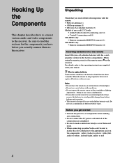
... the power to all components before you don't use a new battery with new ones. z When to the receiver. Before you received the following items with the remote: • FM wire antenna (1) • AM loop antenna (1) • LR6 (size-AA) alkaline batteries (3) Models of time...to the appropriate jacks on the receiver. Be sure to read the sections for an extended period of area code U, CA only • Audio/video/control S connecting cord (1) • Control S connecting cord (1) STR-DE945 only • Remote commander RM-LJ304 (remote) (1) STR-DE845 only • Remote commander RM...
... the power to all components before you don't use a new battery with new ones. z When to the receiver. Before you received the following items with the remote: • FM wire antenna (1) • AM loop antenna (1) • LR6 (size-AA) alkaline batteries (3) Models of time...to the appropriate jacks on the receiver. Be sure to read the sections for an extended period of area code U, CA only • Audio/video/control S connecting cord (1) • Control S connecting cord (1) STR-DE945 only • Remote commander RM-LJ304 (remote) (1) STR-DE845 only • Remote commander RM...
Operating Instructions
Page 5
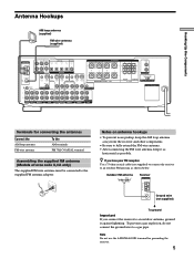
... AUDIO IN AUDIO IN AUDIO OUT AUDIO IN AUDIO OUT AUDIO IN 2ND AUDIO TV/SAT DVD/LD VIDEO 2 VIDEO 1 OUT Terminals for grounding the receiver. 5 FM COAXIAL 75Ω Notes on antenna hookups • To prevent noise pickup, keep the AM loop antenna away from the... receiver and other components. • Be sure to fully extend the FM wire antenna. • After connecting the FM wire antenna, keep it against lightning. Note Do not use the U SIGNAL GND terminal for connecting the...
... AUDIO IN AUDIO IN AUDIO OUT AUDIO IN AUDIO OUT AUDIO IN 2ND AUDIO TV/SAT DVD/LD VIDEO 2 VIDEO 1 OUT Terminals for grounding the receiver. 5 FM COAXIAL 75Ω Notes on antenna hookups • To prevent noise pickup, keep the AM loop antenna away from the... receiver and other components. • Be sure to fully extend the FM wire antenna. • After connecting the FM wire antenna, keep it against lightning. Note Do not use the U SIGNAL GND terminal for connecting the...
Operating Instructions
Page 6
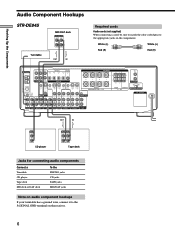
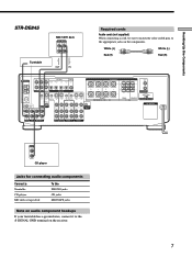
Hooking Up the Components Audio Component Hookups STR-DE945 MD/DAT deck INPUT OUTPUT LINE LINE L R ç ç Turntable OUT IN Required cords Audio cords (not supplied) When connecting a cord, be sure to ... MD/DAT jacks Note on audio component hookups If your turntable has a ground wire, connect it to the appropriate jacks on the receiver. 6 White (L) White (L) Red (R) Red (R) ANTENNA AM y COAXIAL FM 75Ω FRONT REAR L CENTER MD/DAT OUT OPTICAL MD/DAT IN TV/SAT IN DVD/LD IN COAX DVD/LD...
Hooking Up the Components Audio Component Hookups STR-DE945 MD/DAT deck INPUT OUTPUT LINE LINE L R ç ç Turntable OUT IN Required cords Audio cords (not supplied) When connecting a cord, be sure to ... MD/DAT jacks Note on audio component hookups If your turntable has a ground wire, connect it to the appropriate jacks on the receiver. 6 White (L) White (L) Red (R) Red (R) ANTENNA AM y COAXIAL FM 75Ω FRONT REAR L CENTER MD/DAT OUT OPTICAL MD/DAT IN TV/SAT IN DVD/LD IN COAX DVD/LD...
Operating Instructions
Page 7
Hooking Up the Components ç STR-DE845 Turntable MD/TAPE deck INPUT OUTPUT LINE LINE L R ç OUT IN Required cords Audio cords (not supplied) When connecting a cord, be sure to match the ... MD/TAPE jacks Note on audio component hookups If your turntable has a ground wire, connect it to the appropriate jacks on the receiver. 7 White (L) White (L) Red (R) Red (R) ANTENNA AM y COAXIAL FM 75Ω FRONT REAR L CENTER MD/TAPE OUT OPTICAL MD/TAPE IN TV/SAT IN DVD/LD IN COAX DVD/LD...
Hooking Up the Components ç STR-DE845 Turntable MD/TAPE deck INPUT OUTPUT LINE LINE L R ç OUT IN Required cords Audio cords (not supplied) When connecting a cord, be sure to match the ... MD/TAPE jacks Note on audio component hookups If your turntable has a ground wire, connect it to the appropriate jacks on the receiver. 7 White (L) White (L) Red (R) Red (R) ANTENNA AM y COAXIAL FM 75Ω FRONT REAR L CENTER MD/TAPE OUT OPTICAL MD/TAPE IN TV/SAT IN DVD/LD IN COAX DVD/LD...
Operating Instructions
Page 8
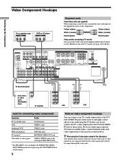
ANTENNA AM y COAXIAL FM 75Ω FRONT REAR L CENTER MD/DAT OUT OPTICAL MD/DAT IN TV/SAT IN DVD/LD IN ...To the TV/SAT jacks VIDEO 1 jacks VIDEO 2 jacks DVD/LD jacks MONITOR VIDEO OUT jack VIDEO 3 INPUT jacks on the receiver and apply sound effects to the audio from the video signals and will not be output through the video jacks. z When using... can connect your TV's audio output jacks to the TV/ SAT AUDIO IN jacks on the front panel (STR-DE945 only) 1) For STR-DE945, you are on the receiver. In this case, do not connect the TV's video output jack to the TV/SAT VIDEO IN jack...
ANTENNA AM y COAXIAL FM 75Ω FRONT REAR L CENTER MD/DAT OUT OPTICAL MD/DAT IN TV/SAT IN DVD/LD IN ...To the TV/SAT jacks VIDEO 1 jacks VIDEO 2 jacks DVD/LD jacks MONITOR VIDEO OUT jack VIDEO 3 INPUT jacks on the receiver and apply sound effects to the audio from the video signals and will not be output through the video jacks. z When using... can connect your TV's audio output jacks to the TV/ SAT AUDIO IN jacks on the front panel (STR-DE945 only) 1) For STR-DE945, you are on the receiver. In this case, do not connect the TV's video output jack to the TV/SAT VIDEO IN jack...

Operating Instructions
Page 9
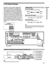
...sure to set to "AUTO." 9 Example of LD player connected via an RF demodulator, like the Sony MOD-RF1 (not supplied). This unit may not operate correctly if INPUT MODE is set INPUT MODE (3... to match the color-coded pins to the appropriate jacks on page 27) manually. TUNING + MEMORY FM/AM FM MODE 2ND AUDIO + SET UP NAME ENTER 0 BASS MUTING EQUALIZER BOOST VIDEO 3 INPUT 10 VIDEO ... Hookups Connect the digital output jacks of your DVD player and satellite tuner (etc.) to the receiver's digital input jacks to bring the multi channel surround sound of a movie theater into your RF...
...sure to set to "AUTO." 9 Example of LD player connected via an RF demodulator, like the Sony MOD-RF1 (not supplied). This unit may not operate correctly if INPUT MODE is set INPUT MODE (3... to match the color-coded pins to the appropriate jacks on page 27) manually. TUNING + MEMORY FM/AM FM MODE 2ND AUDIO + SET UP NAME ENTER 0 BASS MUTING EQUALIZER BOOST VIDEO 3 INPUT 10 VIDEO ... Hookups Connect the digital output jacks of your DVD player and satellite tuner (etc.) to the receiver's digital input jacks to bring the multi channel surround sound of a movie theater into your RF...

Operating Instructions
Page 10
White (L) White (L) Red (R) Red (R) ç ç OUT IN OUT IN ANTENNA AM y COAXIAL FM 75Ω FRONT REAR L CENTER MD/DAT OUT OPTICAL MD/DAT IN TV/SAT IN DVD/LD IN COAX DVD/LD IN R SUB 5.1CH INPUT ... appropriate jacks on your DVD (or LD player) and satellite broadcasts. Using other OPTICAL jacks are compatible with your MD or DAT deck to the receiver's digital output jack. To record digital signals, make analog connections. ç ç Hooking Up the Components Digital Component Hookups Connect the digital output jacks of...
White (L) White (L) Red (R) Red (R) ç ç OUT IN OUT IN ANTENNA AM y COAXIAL FM 75Ω FRONT REAR L CENTER MD/DAT OUT OPTICAL MD/DAT IN TV/SAT IN DVD/LD IN COAX DVD/LD IN R SUB 5.1CH INPUT ... appropriate jacks on your DVD (or LD player) and satellite broadcasts. Using other OPTICAL jacks are compatible with your MD or DAT deck to the receiver's digital output jack. To record digital signals, make analog connections. ç ç Hooking Up the Components Digital Component Hookups Connect the digital output jacks of...
Operating Instructions
Page 11
...VIDEO S-VIDEO OUT OUT IN B + SPEAKERS A R L ++ + R L R L - - - - SPEAKERS FRONT SPEAKERS OFF A B A+B PHONES MULTI CHANNEL DECODING DIMMER DISPLAY INPUT MODE 5.1CH INPUT - TUNING + MEMORY FM/AM FM MODE 2ND AUDIO + SET UP NAME ENTER 0 BASS MUTING EQUALIZER BOOST VIDEO 3 INPUT 10 VIDEO L AUDIO R SPEAKERS REAR/CENTER SUB WOOFER Note See page 16... multi channel decoder, etc., for details on speaker system hookup. Alternatively, the 5.1CH INPUT jacks can connect them directly to this receiver incorporates a multi channel decoder, it is also equipped with 5.1CH INPUT jacks.
...VIDEO S-VIDEO OUT OUT IN B + SPEAKERS A R L ++ + R L R L - - - - SPEAKERS FRONT SPEAKERS OFF A B A+B PHONES MULTI CHANNEL DECODING DIMMER DISPLAY INPUT MODE 5.1CH INPUT - TUNING + MEMORY FM/AM FM MODE 2ND AUDIO + SET UP NAME ENTER 0 BASS MUTING EQUALIZER BOOST VIDEO 3 INPUT 10 VIDEO L AUDIO R SPEAKERS REAR/CENTER SUB WOOFER Note See page 16... multi channel decoder, etc., for details on speaker system hookup. Alternatively, the 5.1CH INPUT jacks can connect them directly to this receiver incorporates a multi channel decoder, it is also equipped with 5.1CH INPUT jacks.
Operating Instructions
Page 12
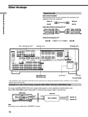
...A White (L/audio) B Red (R/audio) C Black (control S) D Control S connecting cord (1)** Black E Black E CTRL S (STATUS) IN/OUT** CONTROL A1 AC power cord ANTENNA AM y COAXIAL FM 75Ω FRONT REAR L CENTER MD/DAT OUT OPTICAL MD/DAT IN TV/SAT IN DVD/LD IN COAX DVD/LD IN R SUB 5.1CH INPUT... room Stereo amplifier R SPEAKERS L Speaker (L) Speaker (R) Note This function is not available when 5.1CH INPUT is shipped. ** Models of a sub room hookup using the 2ND AUDIO OUT jacks (STR-DE945 only) You can use the 2ND AUDIO OUT jacks to output audio signals to which the receiver is ...
...A White (L/audio) B Red (R/audio) C Black (control S) D Control S connecting cord (1)** Black E Black E CTRL S (STATUS) IN/OUT** CONTROL A1 AC power cord ANTENNA AM y COAXIAL FM 75Ω FRONT REAR L CENTER MD/DAT OUT OPTICAL MD/DAT IN TV/SAT IN DVD/LD IN COAX DVD/LD IN R SUB 5.1CH INPUT... room Stereo amplifier R SPEAKERS L Speaker (L) Speaker (R) Note This function is not available when 5.1CH INPUT is shipped. ** Models of a sub room hookup using the 2ND AUDIO OUT jacks (STR-DE945 only) You can use the 2ND AUDIO OUT jacks to output audio signals to which the receiver is ...
Operating Instructions
Page 13
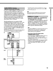
...mode of S-LINK CONTROL S hookups between the receiver, a TV, a VCR, and a DVD player. CONTROL A1 hookup • If you make CONTROL A1 connections from the receiver to an MD deck that is also connected to a computer, do not operate the receiver while using the "Sony MD Editor" software. Note If you have a... CONTROL A1 compatible Sony CD player, tape deck, or MD deck Use a CONTROL A1...
...mode of S-LINK CONTROL S hookups between the receiver, a TV, a VCR, and a DVD player. CONTROL A1 hookup • If you make CONTROL A1 connections from the receiver to an MD deck that is also connected to a computer, do not operate the receiver while using the "Sony MD Editor" software. Note If you have a... CONTROL A1 compatible Sony CD player, tape deck, or MD deck Use a CONTROL A1...
Operating Instructions
Page 14
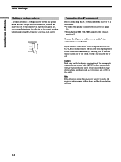
...check that the total power consumption of the component(s) connected to the receiver's AC OUTLET(s) does not exceed the wattage stated on the rear panel of this receiver to a wall outlet: • Connect the speaker system to the receiver (see page 16). • Turn the MASTER VOLUME control to ...or off. VOLTAGE SELECTOR 220V 240V 120V Connecting the AC power cord Before connecting the AC power cord of the receiver is disconnected for about two weeks, the receiver's entire memory will be cleared and the demonstration will supply power to the connected component(s), allowing you to turn...
...check that the total power consumption of the component(s) connected to the receiver's AC OUTLET(s) does not exceed the wattage stated on the rear panel of this receiver to a wall outlet: • Connect the speaker system to the receiver (see page 16). • Turn the MASTER VOLUME control to ...or off. VOLTAGE SELECTOR 220V 240V 120V Connecting the AC power cord Before connecting the AC power cord of the receiver is disconnected for about two weeks, the receiver's entire memory will be cleared and the demonstration will supply power to the connected component(s), allowing you to turn...
Operating Instructions
Page 15
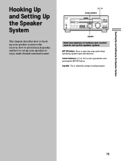
... used to set up the speaker system SET UP button: Press to enter the setup mode when specifying speaker types and distances. TUNING + MEMORY FM/AM FM MODE 2ND AUDIO + SET UP NAME ENTER 0 BASS MUTING EQUALIZER BOOST VIDEO 3 INPUT 10 VIDEO L AUDIO R Jog dial Brief descriptions of each... speaker, and how to set up your speaker system to the receiver, how to select parameters after pressing the SET UP button. SET UP Cursor buttons SPEAKERS OFF A...
... used to set up the speaker system SET UP button: Press to enter the setup mode when specifying speaker types and distances. TUNING + MEMORY FM/AM FM MODE 2ND AUDIO + SET UP NAME ENTER 0 BASS MUTING EQUALIZER BOOST VIDEO 3 INPUT 10 VIDEO L AUDIO R Jog dial Brief descriptions of each... speaker, and how to set up your speaker system to the receiver, how to select parameters after pressing the SET UP button. SET UP Cursor buttons SPEAKERS OFF A...
Operating Instructions
Page 17
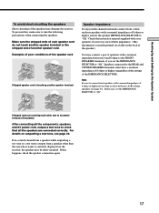
... or higher if you set the speaker IMPEDANCE SELECTOR to select both sets (A+B) of front speakers (see page 22. For details on the receiver, the speaker may damage the receiver. Note Be sure to connect front speakers with a nominal impedance of 8 ohms or higher, and set the IMPEDANCE SELECTOR to "4Ω.". Speakers...
... or higher if you set the speaker IMPEDANCE SELECTOR to select both sets (A+B) of front speakers (see page 22. For details on the receiver, the speaker may damage the receiver. Note Be sure to connect front speakers with a nominal impedance of 8 ohms or higher, and set the IMPEDANCE SELECTOR to "4Ω.". Speakers...
Operating Instructions
Page 18
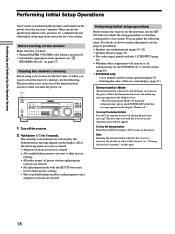
... each program source and preset stations are reset to turn the receiver off automatically via the CONTROL A1 control system (page 50). • STR-DE945 only: - 2 way remote control system operation (page 50). - TUNING + MEMORY FM/AM FM MODE 2ND AUDIO + SET UP NAME ENTER 0 BASS MUTING EQUALIZER ...BOOST VIDEO 3 INPUT 10 VIDEO L AUDIO R 1 Turn off the receiver. 2 Hold down SET UP and press ...
... each program source and preset stations are reset to turn the receiver off automatically via the CONTROL A1 control system (page 50). • STR-DE945 only: - 2 way remote control system operation (page 50). - TUNING + MEMORY FM/AM FM MODE 2ND AUDIO + SET UP NAME ENTER 0 BASS MUTING EQUALIZER ...BOOST VIDEO 3 INPUT 10 VIDEO L AUDIO R 1 Turn off the receiver. 2 Hold down SET UP and press ...
Operating Instructions
Page 19
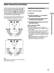
... on the shape of your side B A A 45° C C 90° 20° When placing rear speakers behind you or to the side, depending on the receiver. 2 Press SET UP. 3 Press the cursor buttons ( or ) to select the parameter you want to adjust. 4 Turn the jog dial to the listening position.
... on the shape of your side B A A 45° C C 90° 20° When placing rear speakers behind you or to the side, depending on the receiver. 2 Press SET UP. 3 Press the cursor buttons ( or ) to select the parameter you want to adjust. 4 Turn the jog dial to the listening position.
Operating Instructions
Page 22
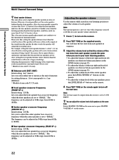
... setting : feet* (meter) Lets you select either feet or meters as the unit of measure for easier speaker volume adjustment. 1 Press ?/1 to turn on the receiver. 2 Press TEST TONE on the remote again to adjust the volume of area code U, CA only. The frequency can not be output when the...
... setting : feet* (meter) Lets you select either feet or meters as the unit of measure for easier speaker volume adjustment. 1 Press ?/1 to turn on the receiver. 2 Press TEST TONE on the remote again to adjust the volume of area code U, CA only. The frequency can not be output when the...


