
Limited Warranty (U.S. Only)
Page 1
..., commercial use, or modification of, or to any authorized Sony service facility. 4-557-173-02 General Stereo/Hifi Components/Tape Decks ® CD Players/Mini Disc Players/Audio Systems Hifi Audio LIMITED WARRANTY Sony Electronics Inc. ("Sony") warrants this Product is valid only in the form of ... limitation on how long an implied warranty lasts, so the above limitations or exclusions may have other than a facility authorized by Sony to service the Product. After the warranty period, you . This warranty gives you specific legal rights, and you . This warranty...
..., commercial use, or modification of, or to any authorized Sony service facility. 4-557-173-02 General Stereo/Hifi Components/Tape Decks ® CD Players/Mini Disc Players/Audio Systems Hifi Audio LIMITED WARRANTY Sony Electronics Inc. ("Sony") warrants this Product is valid only in the form of ... limitation on how long an implied warranty lasts, so the above limitations or exclusions may have other than a facility authorized by Sony to service the Product. After the warranty period, you . This warranty gives you specific legal rights, and you . This warranty...
Operating Instructions
Page 1
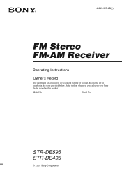
Serial No. Refer to them whenever you call upon your Sony dealer regarding this product. Model No. 4-245-327-15(1) FM Stereo FM-AM Receiver Operating Instructions Owner's Record The model and serial numbers are located at the rear of the unit. Record the serial number in the space provided below. STR-DE595 STR-DE495 © 2003 Sony Corporation
Serial No. Refer to them whenever you call upon your Sony dealer regarding this product. Model No. 4-245-327-15(1) FM Stereo FM-AM Receiver Operating Instructions Owner's Record The model and serial numbers are located at the rear of the unit. Record the serial number in the space provided below. STR-DE595 STR-DE495 © 2003 Sony Corporation
Operating Instructions
Page 2
...- Consult the dealer or an experienced radio/TV technician for energy efficiency. registered mark. As an ENERGY STAR® partner, Sony Corporation has determined that to the presence of it correctly as vases, on the apparatus. Don't throw away the battery with...guarantee that may cause harmful interference to correct the interference by turning the equipment off and on a circuit different from Dolby Laboratories. This receiver incorporates Dolby* Digital and Pro Logic Surround and the DTS** Digital Surround System. * Manufactured under license from that this equipment does ...
...- Consult the dealer or an experienced radio/TV technician for energy efficiency. registered mark. As an ENERGY STAR® partner, Sony Corporation has determined that to the presence of it correctly as vases, on the apparatus. Don't throw away the battery with...guarantee that may cause harmful interference to correct the interference by turning the equipment off and on a circuit different from Dolby Laboratories. This receiver incorporates Dolby* Digital and Pro Logic Surround and the DTS** Digital Surround System. * Manufactured under license from that this equipment does ...

Operating Instructions
Page 3
...Changing the display 22 Enjoying Surround Sound Using only the front speakers (2 Channel Stereo 23 Enjoying higher fidelity sound 23 Selecting a sound field 24 Understanding the multi channel surround displays 26 Customizing sound fields 27 Receiving Broadcasts Storing FM stations automatically (AUTOBETICAL)2 29 Direct tuning 29 Automatic tuning 30 Preset tuning 30... Precautions 41 Troubleshooting 41 Specifications 44 Tables of settings using the MAIN MENU button 47 Adjustable parameters for each sound field back page 1) STR-DE595 only. 2) Models of area code CEL, CEK only. 3GB
...Changing the display 22 Enjoying Surround Sound Using only the front speakers (2 Channel Stereo 23 Enjoying higher fidelity sound 23 Selecting a sound field 24 Understanding the multi channel surround displays 26 Customizing sound fields 27 Receiving Broadcasts Storing FM stations automatically (AUTOBETICAL)2 29 Direct tuning 29 Automatic tuning 30 Preset tuning 30... Precautions 41 Troubleshooting 41 Specifications 44 Tables of settings using the MAIN MENU button 47 Adjustable parameters for each sound field back page 1) STR-DE595 only. 2) Models of area code CEL, CEK only. 3GB
Operating Instructions
Page 4
...; 4-XXX-XXX-XX AA Area code Any differences in operation, according to the area code, are for models STR-DE595 and STR-DE495. RL + + - - Check your remote, see the illustration below). For details on the receiver. About This Manual The instructions in this manual describe the controls on the lower portion of the rear...
...; 4-XXX-XXX-XX AA Area code Any differences in operation, according to the area code, are for models STR-DE595 and STR-DE495. RL + + - - Check your remote, see the illustration below). For details on the receiver. About This Manual The instructions in this manual describe the controls on the lower portion of the rear...
Operating Instructions
Page 5
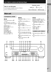
...) MUSIC (button/indicator) ql (24, 25, 42) P - wf (31, 46) SPEAKERS (OFF/A/B/A+B) (STR-DE595 only) wl (13, 22, 41) TUNER FM/AM q; (21, 30, 31, 34) TUNING +/- L A.F.D. (button/indicator) wa (23-25) CD (STR-DE495 only) 9 (21) CD/SACD (STR-DE595 only) 9 (21) DIMMER 3 (22) DISPLAY 2 (22, 32, 43) Display qa (22)... DVD 7 (21) ENTER qg (34, 36) FM MODE wh (30) INPUT MODE qd (21) IR (receptor) 4 (37, 43) M - List ...
...) MUSIC (button/indicator) ql (24, 25, 42) P - wf (31, 46) SPEAKERS (OFF/A/B/A+B) (STR-DE595 only) wl (13, 22, 41) TUNER FM/AM q; (21, 30, 31, 34) TUNING +/- L A.F.D. (button/indicator) wa (23-25) CD (STR-DE495 only) 9 (21) CD/SACD (STR-DE595 only) 9 (21) DIMMER 3 (22) DISPLAY 2 (22, 32, 43) Display qa (22)... DVD 7 (21) ENTER qg (34, 36) FM MODE wh (30) INPUT MODE qd (21) IR (receptor) 4 (37, 43) M - List ...
Operating Instructions
Page 6
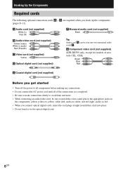
white (left, audio) to yellow; G Component video cord (not supplied) (STR-DE595 only, except for models of the connections are required when you hook up the components (pages 8-11). and red (right, audio) to red. • ...
white (left, audio) to yellow; G Component video cord (not supplied) (STR-DE595 only, except for models of the connections are required when you hook up the components (pages 8-11). and red (right, audio) to red. • ...
Operating Instructions
Page 7
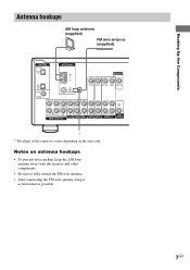
Hooking Up the Components Antenna hookups AM loop antenna (supplied) FM wire antenna (supplied) DIGITAL OPTICAL VIDEO 2 IN CD/ SACD IN DVD IN COAXIAL L ANTENNA AM y MONITOR VIDEO IN VIDEO IN VIDEO OUT VIDEO IN VIDEO ... the connector varies depending on antenna hookups • To prevent noise pickup, keep the AM loop antenna away from the receiver and other components. • Be sure to fully extend the FM wire antenna. • After connecting the FM wire antenna, keep it as horizontal as possible. 7GB Notes on the area code.
Hooking Up the Components Antenna hookups AM loop antenna (supplied) FM wire antenna (supplied) DIGITAL OPTICAL VIDEO 2 IN CD/ SACD IN DVD IN COAXIAL L ANTENNA AM y MONITOR VIDEO IN VIDEO IN VIDEO OUT VIDEO IN VIDEO ... the connector varies depending on antenna hookups • To prevent noise pickup, keep the AM loop antenna away from the receiver and other components. • Be sure to fully extend the FM wire antenna. • After connecting the FM wire antenna, keep it as horizontal as possible. 7GB Notes on the area code.
Operating Instructions
Page 8
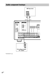
Audio component hookups MD/Tape deck INPUT OUTPUT LINE LINE L R A A OUT IN ç ç DIGITAL OPTICAL VIDEO 2 IN CD/ SACD IN DVD IN COAXIAL L ANTENNA AM y CENTER L L MONITOR VIDEO IN VIDEO IN VIDEO OUT VIDEO IN VIDEO OUT L L AUDIO OUT R FRONT SURROUND SUB WOOFER IN R OUT R IN CD/SACD MD/TAPE MULTI CH IN AUDIO IN R AUDIO IN AUDIO OUT R AUDIO IN SUB DVD VIDEO 2 VIDEO 1 WOOFER * STR-DE595 only. A OUTPUT LINE L R CD or Super Audio CD* player 8GB
Audio component hookups MD/Tape deck INPUT OUTPUT LINE LINE L R A A OUT IN ç ç DIGITAL OPTICAL VIDEO 2 IN CD/ SACD IN DVD IN COAXIAL L ANTENNA AM y CENTER L L MONITOR VIDEO IN VIDEO IN VIDEO OUT VIDEO IN VIDEO OUT L L AUDIO OUT R FRONT SURROUND SUB WOOFER IN R OUT R IN CD/SACD MD/TAPE MULTI CH IN AUDIO IN R AUDIO IN AUDIO OUT R AUDIO IN SUB DVD VIDEO 2 VIDEO 1 WOOFER * STR-DE595 only. A OUTPUT LINE L R CD or Super Audio CD* player 8GB

Operating Instructions
Page 9
...COMPONENT VIDEO (Y, B-Y, R-Y) output jacks and a monitor with COMPONENT VIDEO input jacks, use a component video cord (not supplied) to connect to the receiver. 9GB STR-DE595 only, except for models of area code CEL, CEK If you are connecting a separate satellite tuner, connect both the audio and video output jacks... to the receiver as shown above. In this case, do not connect the TV's video output jack to the audio from the ...
...COMPONENT VIDEO (Y, B-Y, R-Y) output jacks and a monitor with COMPONENT VIDEO input jacks, use a component video cord (not supplied) to connect to the receiver. 9GB STR-DE595 only, except for models of area code CEL, CEK If you are connecting a separate satellite tuner, connect both the audio and video output jacks... to the receiver as shown above. In this case, do not connect the TV's video output jack to the audio from the ...
Operating Instructions
Page 10
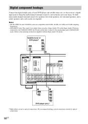
... COAXIAL jacks are required. Refer to the operating instructions supplied with 96 kHz, 48 kHz, 44.1 kHz and 32 kHz sampling frequencies. • (STR-DE595 only) The sound is not output when you play a Super Audio CD on the Super Audio CD player connected to the CD/SACD OPTICAL...Audio CD player. Connect to bring the multi channel surround sound of a movie theater into your DVD player and satellite tuner (etc.) to the receiver's digital input jacks to the analog input jacks (CD/SACD IN jacks). We recommend making coaxial connections instead of optical connections. 10GB Digital component ...
... COAXIAL jacks are required. Refer to the operating instructions supplied with 96 kHz, 48 kHz, 44.1 kHz and 32 kHz sampling frequencies. • (STR-DE595 only) The sound is not output when you play a Super Audio CD on the Super Audio CD player connected to the CD/SACD OPTICAL...Audio CD player. Connect to bring the multi channel surround sound of a movie theater into your DVD player and satellite tuner (etc.) to the receiver's digital input jacks to the analog input jacks (CD/SACD IN jacks). We recommend making coaxial connections instead of optical connections. 10GB Digital component ...
Operating Instructions
Page 11
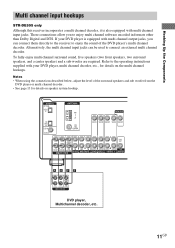
... you can be used to connect an external multi channel decoder. Alternatively, the multi channel input jacks can connect them directly to the receiver to enjoy the sound of the surround speakers and sub woofer from the DVD player or multi channel decoder. • See page 13... for details on speaker system hookup. Hooking Up the Components Multi channel input hookups STR-DE595 only Although this receiver incorporates a multi channel decoder, it is equipped with multi channel input jacks. If your DVD player, multi channel decoder, etc., for...
... you can be used to connect an external multi channel decoder. Alternatively, the multi channel input jacks can connect them directly to the receiver to enjoy the sound of the surround speakers and sub woofer from the DVD player or multi channel decoder. • See page 13... for details on speaker system hookup. Hooking Up the Components Multi channel input hookups STR-DE595 only Although this receiver incorporates a multi channel decoder, it is equipped with multi channel input jacks. If your DVD player, multi channel decoder, etc., for...
Operating Instructions
Page 12
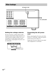
... wall outlet Setting the voltage selector If your audio/ video components to the local power supply voltage. Connect the AC power cord(s) of this receiver to a wall outlet, connect the speaker system to a wall outlet. VOLTAGE SELECTOR 120V 220V 240V Connecting the AC power cord Before connecting the... AC power cord of your receiver has a voltage selector on the rear panel, check that the voltage selector is set the selector to the correct position before connecting the...
... wall outlet Setting the voltage selector If your audio/ video components to the local power supply voltage. Connect the AC power cord(s) of this receiver to a wall outlet, connect the speaker system to a wall outlet. VOLTAGE SELECTOR 120V 220V 240V Connecting the AC power cord Before connecting the... AC power cord of your receiver has a voltage selector on the rear panel, check that the voltage selector is set the selector to the correct position before connecting the...
Operating Instructions
Page 13
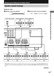
... FRONT B RL RL FRONT A CENTER SURROUND SPEAKERS IMPEDANCE USE 8-16Ω A A A A A E e Ee Ee Ee Ee Front speaker B* Front speaker B* Center speaker Surround speaker Surround speaker (R) (L) (R) (L) * (STR-DE595 only) If you want to the SPEAKERS FRONT B terminals.
... FRONT B RL RL FRONT A CENTER SURROUND SPEAKERS IMPEDANCE USE 8-16Ω A A A A A E e Ee Ee Ee Ee Front speaker B* Front speaker B* Center speaker Surround speaker Surround speaker (R) (L) (R) (L) * (STR-DE595 only) If you want to the SPEAKERS FRONT B terminals.
Operating Instructions
Page 14
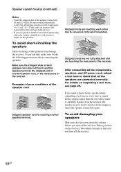
...short-circuited. To avoid short-circuiting the speakers Short-circuiting of the speaker cord Stripped speaker cord is currently displayed on the receiver, the speaker may damage the receiver. For details on the speakers. When you turn on the components: + to -. Speaker system hookup (continued) Notes &#...8226; Twist the stripped ends of the receiver. Examples of poor conditions of the speakers may be distorted and will lack bass. • If you use speakers with low maximum ...
...short-circuited. To avoid short-circuiting the speakers Short-circuiting of the speaker cord Stripped speaker cord is currently displayed on the receiver, the speaker may damage the receiver. For details on the speakers. When you turn on the components: + to -. Speaker system hookup (continued) Notes &#...8226; Twist the stripped ends of the receiver. Examples of poor conditions of the speakers may be distorted and will lack bass. • If you use speakers with low maximum ...
Operating Instructions
Page 15
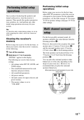
..., etc.) and perform any other settings. The front speakers can place the surround speakers either behind you or to the listening position. Clearing the receiver's memory Before using your side (long room) B A A 45° C C 90° 20° continued 15GB Performing initial setup operations... Before using your room (etc.). Tip To check the audio output during settings (to set to your receiver for the first time, or when you place the center speaker up to 1.5 meters (5 feet) closer (B) and the surround speakers up...
..., etc.) and perform any other settings. The front speakers can place the surround speakers either behind you or to the listening position. Clearing the receiver's memory Before using your side (long room) B A A 45° C C 90° 20° continued 15GB Performing initial setup operations... Before using your room (etc.). Tip To check the audio output during settings (to set to your receiver for the first time, or when you place the center speaker up to 1.5 meters (5 feet) closer (B) and the surround speakers up...
Operating Instructions
Page 16
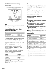
... you use Micro Satellite Speakers and the speaker size is entered automatically. 4 Repeat steps 2 and 3 until you have set this parameter only when you use Sony's Micro Satellite Speakers, select "MICRO SP.". Caution When you select "NORM. Specifying the speaker parameters 1 Press MAIN MENU repeatedly to select " SET UP ". 2 Press MENU...
... you use Micro Satellite Speakers and the speaker size is entered automatically. 4 Repeat steps 2 and 3 until you have set this parameter only when you use Sony's Micro Satellite Speakers, select "MICRO SP.". Caution When you select "NORM. Specifying the speaker parameters 1 Press MAIN MENU repeatedly to select " SET UP ". 2 Press MENU...
Operating Instructions
Page 17
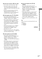
... from other "LARGE" speakers. • If you do not connect surround speakers, select "NO".*3 Tip *1-*3 correspond to the following Dolby Pro Logic modes *1 NORMAL *2 PHANTOM *3 3 STEREO continued 17GB x Front speaker size ( L R XXXXX) • If you connect large speakers that you set to "LARGE") or sub woofer.*1 • If you feel a lack...
... from other "LARGE" speakers. • If you do not connect surround speakers, select "NO".*3 Tip *1-*3 correspond to the following Dolby Pro Logic modes *1 NORMAL *2 PHANTOM *3 3 STEREO continued 17GB x Front speaker size ( L R XXXXX) • If you connect large speakers that you set to "LARGE") or sub woofer.*1 • If you feel a lack...
Operating Instructions
Page 18
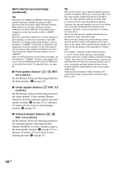
... speaker distance should be set it is further away. For example, setting the center speaker distance 1~2 m (3~6 feet) closer than 4.5 meters (15 feet) closer. Tip The receiver allows you want to output the bass frequencies from that speaker. However, it to "SMALL". Multi channel surround setup (continued) Tip Internally, the LARGE and...
... speaker distance should be set it is further away. For example, setting the center speaker distance 1~2 m (3~6 feet) closer than 4.5 meters (15 feet) closer. Tip The receiver allows you want to output the bass frequencies from that speaker. However, it to "SMALL". Multi channel surround setup (continued) Tip Internally, the LARGE and...
Operating Instructions
Page 19
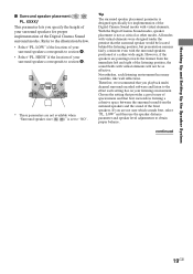
Choose the setting that provides a good sense of your surround speakers corresponds to section A. • Select "PL. LOW" if the location of spaciousness and that you playback multi channel surround encoded software and listen to obtain proper balance. HIGH" if the location of the Digital Cinema Sound modes with the surround speakers positioned at a rather wide angle. With the Digital Cinema Sound modes, speaker placement is set to the illustration below. • Select "PL. All modes with virtual elements were designed under the premise that the surround speaker ...
Choose the setting that provides a good sense of your surround speakers corresponds to section A. • Select "PL. LOW" if the location of spaciousness and that you playback multi channel surround encoded software and listen to obtain proper balance. HIGH" if the location of the Digital Cinema Sound modes with the surround speakers positioned at a rather wide angle. With the Digital Cinema Sound modes, speaker placement is set to the illustration below. • Select "PL. All modes with virtual elements were designed under the premise that the surround speaker ...
