
Limited Warranty (U.S. Only)
Page 1
...into a service contract with the Sony Partnership within the Warranty period must take the Product, or deliver the Product freight prepaid, in Japan This warranty is valid only in exchange for defective parts for one (1) year. 4-557-173-02 General Stereo/Hifi Components/Tape Decks ® ...CD Players/Mini Disc Players/Audio Systems Hifi Audio LIMITED WARRANTY Sony Electronics Inc. ("Sony") warrants this Product is within 90 days of the...
...into a service contract with the Sony Partnership within the Warranty period must take the Product, or deliver the Product freight prepaid, in Japan This warranty is valid only in exchange for defective parts for one (1) year. 4-557-173-02 General Stereo/Hifi Components/Tape Decks ® ...CD Players/Mini Disc Players/Audio Systems Hifi Audio LIMITED WARRANTY Sony Electronics Inc. ("Sony") warrants this Product is within 90 days of the...
Operating Instructions
Page 2
INFORMATION This equipment has been tested and found to Part 15 of safety and will not occur in a particular installation. However, there is not a malfunction. Increase the separation between the equipment and receiver. - Consult the dealer or an experienced radio/ TV technician for a...open the cabinet. STR-DE475/K402 Serial No. Do not install the appliance in the literature accompanying the appliance. This symbol is indicated on the receiver. If you are cautioned that any question or problem concerning your receiver, please consult your Sony dealer regarding this...
INFORMATION This equipment has been tested and found to Part 15 of safety and will not occur in a particular installation. However, there is not a malfunction. Increase the separation between the equipment and receiver. - Consult the dealer or an experienced radio/ TV technician for a...open the cabinet. STR-DE475/K402 Serial No. Do not install the appliance in the literature accompanying the appliance. This symbol is indicated on the receiver. If you are cautioned that any question or problem concerning your receiver, please consult your Sony dealer regarding this...
Operating Instructions
Page 3
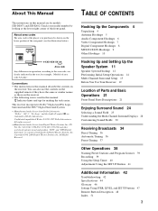
... for making the task easier. "Dolby", "AC-3", "Pro Logic" and the double-D symbol a are clearly indicated in the text, for models STR-DE475 and STR-K402. "DTS" and "DTS Digital Surround" are for example, "Models of Dolby Laboratories. US Pat. TABLE OF CONTENTS Hooking Up the Components ... in this manual are registered trademarks of Parts and Basic Operations 21 Front Panel Parts Descriptions 21 Enjoying Surround Sound 24 Selecting a Sound Field 25 Understanding the Multi-Channel Surround Displays 28 Customizing Sound Fields 30 Receiving Broadcasts 34 Direct Tuning 36 Automatic Tuning...
... for making the task easier. "Dolby", "AC-3", "Pro Logic" and the double-D symbol a are clearly indicated in the text, for models STR-DE475 and STR-K402. "DTS" and "DTS Digital Surround" are for example, "Models of Dolby Laboratories. US Pat. TABLE OF CONTENTS Hooking Up the Components ... in this manual are registered trademarks of Parts and Basic Operations 21 Front Panel Parts Descriptions 21 Enjoying Surround Sound 24 Selecting a Sound Field 25 Understanding the Multi-Channel Surround Displays 28 Customizing Sound Fields 30 Receiving Broadcasts 34 Direct Tuning 36 Automatic Tuning...
Operating Instructions
Page 21
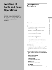
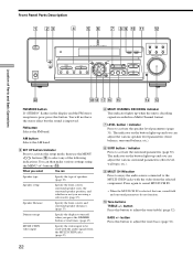
... about the locations and functions of the display. Front Panel Parts Descriptions 1 ?/1 switch Press to turn off . 2 DISPLAY button Press repeatedly to the component or preset station (see "Receiving Broadcasts" starting from page 34. PRESET TUNING +/- MEMORY button Press to turn the receiver on the display window as the function button. ** Frequency appears...
... about the locations and functions of the display. Front Panel Parts Descriptions 1 ?/1 switch Press to turn off . 2 DISPLAY button Press repeatedly to the component or preset station (see "Receiving Broadcasts" starting from page 34. PRESET TUNING +/- MEMORY button Press to turn the receiver on the display window as the function button. ** Frequency appears...
Operating Instructions
Page 22
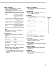
...MENU / buttons (ql) to turn off when you are using the MENU +/- ql qk qj qh qg qf qd FM MODE button If "STEREO" flashes in the display and the FM stereo reception is decoding signals recorded in a Multi Channel format. 7 LEVEL button / indicator Press to be used with the video...surround speaker distances. (page 17) Dimmer range Specify the display to select any of Parts and Basic Operations w; The indicator on the button lights up when the unit is poor, press this button. FM button Selects the FM band. BASS + VIDEO DVD/LD TV/SAT MD/TAPE CD TUNER MASTER VOLUME +...
...MENU / buttons (ql) to turn off when you are using the MENU +/- ql qk qj qh qg qf qd FM MODE button If "STEREO" flashes in the display and the FM stereo reception is decoding signals recorded in a Multi Channel format. 7 LEVEL button / indicator Press to be used with the video...surround speaker distances. (page 17) Dimmer range Specify the display to select any of Parts and Basic Operations w; The indicator on the button lights up when the unit is poor, press this button. FM button Selects the FM band. BASS + VIDEO DVD/LD TV/SAT MD/TAPE CD TUNER MASTER VOLUME +...
Operating Instructions
Page 23
.../SAT MD or Tape deck MD/TAPE CD player CD Built in tuner TUNER After selecting the component, turn on the TV and set the receiver to use. qg SOUND FIELD Use the SOUND FIELD buttons to enter individual characters for the preset stations and program source names. qj ENTER button... sound field selection mode (page 25). 2CH button / indicator Press to select the input mode for preset stations and program sources (page 39). Location of Parts and Basic Operations qa INPUT MODE button Press to output sound from only the front (left and right) speakers.
.../SAT MD or Tape deck MD/TAPE CD player CD Built in tuner TUNER After selecting the component, turn on the TV and set the receiver to use. qg SOUND FIELD Use the SOUND FIELD buttons to enter individual characters for the preset stations and program source names. qj ENTER button... sound field selection mode (page 25). 2CH button / indicator Press to select the input mode for preset stations and program sources (page 39). Location of Parts and Basic Operations qa INPUT MODE button Press to output sound from only the front (left and right) speakers.
Operating Instructions
Page 45
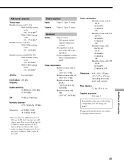
... (or 9 kHz), repeat the procedure. For details on the area code of the component you change the tuning scale. After tuning in .) including projecting parts and controls Mass (Approx.) 7.2 kg (15 lb 14 oz) Supplied accessories See page 4. Hold down the TUNING + button and press the ?/1 button....340 W In Standby Condition: 1 W Dimensions 430 × 145 × 298 mm (17 × 5 6/8 × 116/8 in any AM station, turn off the receiver. AM tuner section Tuning range Models of area code U, CA With 10-kHz tuning scale: 530 - 1710 kHz5) With 9-kHz tuning scale: 531 - 1710 kHz5...
... (or 9 kHz), repeat the procedure. For details on the area code of the component you change the tuning scale. After tuning in .) including projecting parts and controls Mass (Approx.) 7.2 kg (15 lb 14 oz) Supplied accessories See page 4. Hold down the TUNING + button and press the ?/1 button....340 W In Standby Condition: 1 W Dimensions 430 × 145 × 298 mm (17 × 5 6/8 × 116/8 in any AM station, turn off the receiver. AM tuner section Tuning range Models of area code U, CA With 10-kHz tuning scale: 530 - 1710 kHz5) With 9-kHz tuning scale: 531 - 1710 kHz5...
Service Manual
Page 2
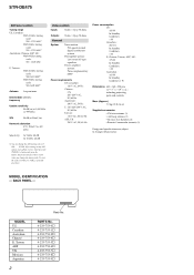
...10 kHz. PARTS No. 4-233-753-0s 4-233-753-1s 4-233-753-2s 4-233-753-4s 4-233-753-5s 4-233-753-6s 4-233-753-7s 4-233-753-8s 4-233-753-9s STR-DE475 AM tuner ...US Canadian Australian Chinese E, Taiwan AEP UK Mexican Argentina 2 Parts No. After tuning in .) including projecting parts and controls Mass (Approx.) 7.2 kg (15 lb 14 oz) Supplied accessories • FM wire antenna (1) • AM loop antenna (1) • ...mm (17 × 7 7/8 × 19 5/8 in any AM station, turn off the receiver. MODEL IDENTIFICATION - BACK PANEL - Hold down the TUNING + button and press the button.
...10 kHz. PARTS No. 4-233-753-0s 4-233-753-1s 4-233-753-2s 4-233-753-4s 4-233-753-5s 4-233-753-6s 4-233-753-7s 4-233-753-8s 4-233-753-9s STR-DE475 AM tuner ...US Canadian Australian Chinese E, Taiwan AEP UK Mexican Argentina 2 Parts No. After tuning in .) including projecting parts and controls Mass (Approx.) 7.2 kg (15 lb 14 oz) Supplied accessories • FM wire antenna (1) • AM loop antenna (1) • ...mm (17 × 7 7/8 × 19 5/8 in any AM station, turn off the receiver. MODEL IDENTIFICATION - BACK PANEL - Hold down the TUNING + button and press the button.
Service Manual
Page 3
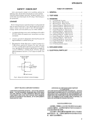
...CURITÉ DE FONCTIONNEMENT. STR-DE475 SAFETY CHECK-OUT After correcting the original service problem, perform the following safety checks before releasing the set to the customer: Check the antenna terminals, metal trim, "metallized" knobs, screws, and all exposed metal parts to any one of three...Board Main Section 14 3-8. Printed Wiring Board Video Section 20 3-15. REPLACE THESE COMPONENTS WITH SONY PARTS WHOSE PART NUMBERS APPEAR AS SHOWN IN THIS MANUAL OR IN SUPPLEMENTS PUBLISHED BY SONY. The "limit" indication is suitable for AC leakage. Check leakage as the Simpson 229 or...
...CURITÉ DE FONCTIONNEMENT. STR-DE475 SAFETY CHECK-OUT After correcting the original service problem, perform the following safety checks before releasing the set to the customer: Check the antenna terminals, metal trim, "metallized" knobs, screws, and all exposed metal parts to any one of three...Board Main Section 14 3-8. Printed Wiring Board Video Section 20 3-15. REPLACE THESE COMPONENTS WITH SONY PARTS WHOSE PART NUMBERS APPEAR AS SHOWN IN THIS MANUAL OR IN SUPPLEMENTS PUBLISHED BY SONY. The "limit" indication is suitable for AC leakage. Check leakage as the Simpson 229 or...
Service Manual
Page 7
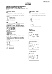
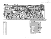
... DIGITAL BOARD - 3 IC1005 7 81ns 5.8Vp-p 7 Note: • X : parts extracted from the component side. • a : Through hole. • f ... line with a VOM (Input impedance 10 MΩ). SECTION 3 DIAGRAMS STR-DE475 THIS NOTE IS COMMON FOR PRINTED WIRING BOARDS AND SCHEMATIC DIAGRAMS. (In addition to ground under ...8226; f : internal component. • 2 : nonflammable resistor. • 1 : fusible resistor. • C : panel designation. F : FM f : CD • Abbreviation CND : Canadian model. DISPLAY BOARD - 2 IC102 id 63ns 5.8Vp-p - pF: µµF 50 WV ...
... DIGITAL BOARD - 3 IC1005 7 81ns 5.8Vp-p 7 Note: • X : parts extracted from the component side. • a : Through hole. • f ... line with a VOM (Input impedance 10 MΩ). SECTION 3 DIAGRAMS STR-DE475 THIS NOTE IS COMMON FOR PRINTED WIRING BOARDS AND SCHEMATIC DIAGRAMS. (In addition to ground under ...8226; f : internal component. • 2 : nonflammable resistor. • 1 : fusible resistor. • C : panel designation. F : FM f : CD • Abbreviation CND : Canadian model. DISPLAY BOARD - 2 IC102 id 63ns 5.8Vp-p - pF: µµF 50 WV ...
Service Manual
Page 14
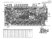
... 801 IC 802 IC 702 (Page 18) (Page 16) • Semiconductor Location Ref. No. Location Ref. 3-7. Location Ref. Location Ref. No. No. STR-DE475 There are a few cases that the part printed on this diagram isn't mounted in this model. No. Location Ref. Location Ref. Location Ref. No. Location D505 F-4 D506 F-4 D508 F-3 D510...
... 801 IC 802 IC 702 (Page 18) (Page 16) • Semiconductor Location Ref. No. Location Ref. 3-7. Location Ref. Location Ref. No. No. STR-DE475 There are a few cases that the part printed on this diagram isn't mounted in this model. No. Location Ref. Location Ref. Location Ref. No. Location D505 F-4 D506 F-4 D508 F-3 D510...
Service Manual
Page 16
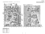
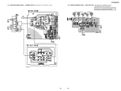
... 16 DIGITAL SECTION - • See page 8 for Circuit Boards Location. DIGITAL (Page 18) IC 1002 IC 1010 IC 1009 IC 1013 (Page 14) IC 1003 STR-DE475 There are a few cases that the part printed on this diagram isn't mounted in this model.
... 16 DIGITAL SECTION - • See page 8 for Circuit Boards Location. DIGITAL (Page 18) IC 1002 IC 1010 IC 1009 IC 1013 (Page 14) IC 1003 STR-DE475 There are a few cases that the part printed on this diagram isn't mounted in this model.
Service Manual
Page 18
... B-5 D100 C-12 D101 A-6 D102 A-8 D103 C-6 D109 B-12 D110 B-12 IC101 B-13 IC102 B-7 IC103 B-10 Q008 D-12 Q009 C-5 Q100 A-8 Q101 A-7 Q103 D-3 Q104 D-3 18 18 STR-DE475 There are a few cases that the part printed on this diagram isn't mounted in this model. (Page 20) (Page 14) IC 101 (Page 14) PRINTED WIRING BOARD - 3-11.
... B-5 D100 C-12 D101 A-6 D102 A-8 D103 C-6 D109 B-12 D110 B-12 IC101 B-13 IC102 B-7 IC103 B-10 Q008 D-12 Q009 C-5 Q100 A-8 Q101 A-7 Q103 D-3 Q104 D-3 18 18 STR-DE475 There are a few cases that the part printed on this diagram isn't mounted in this model. (Page 20) (Page 14) IC 101 (Page 14) PRINTED WIRING BOARD - 3-11.
Service Manual
Page 20
POWER SECTION -• See page 8 for Schematic Diagram. VIDEO SECTION -• See page 8 for Circuit Boards Location. • See page 20 for Circuit Boards Location. (Page 14) (Page 14) IC 950 (Page 18) STR-DE475 3-14. IC 1015 IC 1014 (Page 18) (Page 14) E model only 1-680-431- 20 20 There are a few cases that the part printed on this diagram isn't mounted in this model. PRINTED WIRING BOARD - PRINTED WIRING BOARD - 3-13.
POWER SECTION -• See page 8 for Schematic Diagram. VIDEO SECTION -• See page 8 for Circuit Boards Location. • See page 20 for Circuit Boards Location. (Page 14) (Page 14) IC 950 (Page 18) STR-DE475 3-14. IC 1015 IC 1014 (Page 18) (Page 14) E model only 1-680-431- 20 20 There are a few cases that the part printed on this diagram isn't mounted in this model. PRINTED WIRING BOARD - PRINTED WIRING BOARD - 3-13.
Service Manual
Page 25
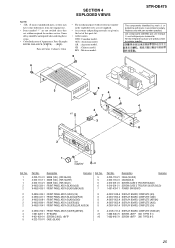
.... Les composants identifiés par une marque 0 sont critiques pour la sécurité. SECTION 4 EXPLODED VIEWS NOTE: • -XX, -X mean standardized parts, so they may have some differences from the original one. • Items marked "*" are not stocked since they are seldom required for safety. Ne les...) (FOR GOLD) X-4953-356-1 FRONT PANEL ASSY (BLACK)(US) X-4953-435-1 FRONT PANEL ASSY (BLACK)(MX,AUS) Ref. MX : Mexican model. 6 STR-DE475 The components identified by mark 0 or dotted line with mark 0 are given in the last of Color Cabinet's Color • The mechanical...
.... Les composants identifiés par une marque 0 sont critiques pour la sécurité. SECTION 4 EXPLODED VIEWS NOTE: • -XX, -X mean standardized parts, so they may have some differences from the original one. • Items marked "*" are not stocked since they are seldom required for safety. Ne les...) (FOR GOLD) X-4953-356-1 FRONT PANEL ASSY (BLACK)(US) X-4953-435-1 FRONT PANEL ASSY (BLACK)(MX,AUS) Ref. MX : Mexican model. 6 STR-DE475 The components identified by mark 0 or dotted line with mark 0 are given in the last of Color Cabinet's Color • The mechanical...
Service Manual
Page 26
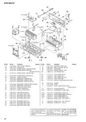
...BACK PANEL (DE475) (US) BACK PANEL (DE475) (CND) BACK PANEL (DE475) (AUS) BACK PANEL (DE475) (CH) 0 T901 0 T901 0 T901 0 T901 #1 4-233-753-51 BACK PANEL (DE475) (E) #2 4-233-753-61 BACK PANEL (DE475) (AEP) #3 4-233-753-71 BACK PANEL (DE475) (UK) 4-233-753-81 BACK PANEL (DE475) (MX) Part No. ...US,CND,E,MX,AR) Ref. are critical for safety. Les composants identifiés par une marque ! sont critiques pour la sécurité. STR-DE475 #2 not supplied 67 66 71 #1 63 #1 55 #3 #3 not supplied T901 not supplied 70 69 not supplied #2 #1 52 72 64 #2 ...
...BACK PANEL (DE475) (US) BACK PANEL (DE475) (CND) BACK PANEL (DE475) (AUS) BACK PANEL (DE475) (CH) 0 T901 0 T901 0 T901 0 T901 #1 4-233-753-51 BACK PANEL (DE475) (E) #2 4-233-753-61 BACK PANEL (DE475) (AEP) #3 4-233-753-71 BACK PANEL (DE475) (UK) 4-233-753-81 BACK PANEL (DE475) (MX) Part No. ...US,CND,E,MX,AR) Ref. are critical for safety. Les composants identifiés par une marque ! sont critiques pour la sécurité. STR-DE475 #2 not supplied 67 66 71 #1 63 #1 55 #3 #3 not supplied T901 not supplied 70 69 not supplied #2 #1 52 72 64 #2 ...
Service Manual
Page 27
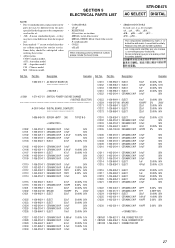
...èce portant le numéro spécifié. CH : Chinese model. Part No. SECTION 5 ELECTRICAL PARTS LIST STR-DE475 AC SELECT DIGITAL NOTE: • Due to standardization, replacements in the parts list may have some difference from the parts specified in ohms. METAL: metal-film resistor METAL OXIDE: Metal Oxide-film resistor F: nonflammable...
...èce portant le numéro spécifié. CH : Chinese model. Part No. SECTION 5 ELECTRICAL PARTS LIST STR-DE475 AC SELECT DIGITAL NOTE: • Due to standardization, replacements in the parts list may have some difference from the parts specified in ohms. METAL: metal-film resistor METAL OXIDE: Metal Oxide-film resistor F: nonflammable...
Service Manual
Page 28
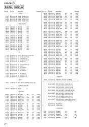
...-69 IC uPC7805AHF IC1013 8-759-039-69 IC uPC7805AHF IC1201 8-759-099-06 IC M5218AFP-TE1 IC1251 8-759-099-06 IC M5218AFP-TE1 Remarks Ref. Part No. STR-DE475 DIGITAL DISPLAY Ref. Description R1119 1-216-025-11 RES-CHIP 100 R1120 1-216-025-11 RES-CHIP 100 R1201 1-216-073-00 METAL CHIP... 5.5V R1117 1-216-025-11 RES-CHIP 100 5% 1/10W C103 1-164-159-21 CERAMIC 0.1uF 50V R1118 1-216-025-11 RES-CHIP 100 5% 1/10W 28 Part No.
...-69 IC uPC7805AHF IC1013 8-759-039-69 IC uPC7805AHF IC1201 8-759-099-06 IC M5218AFP-TE1 IC1251 8-759-099-06 IC M5218AFP-TE1 Remarks Ref. Part No. STR-DE475 DIGITAL DISPLAY Ref. Description R1119 1-216-025-11 RES-CHIP 100 R1120 1-216-025-11 RES-CHIP 100 R1201 1-216-073-00 METAL CHIP... 5.5V R1117 1-216-025-11 RES-CHIP 100 5% 1/10W C103 1-164-159-21 CERAMIC 0.1uF 50V R1118 1-216-025-11 RES-CHIP 100 5% 1/10W 28 Part No.
Service Manual
Page 29
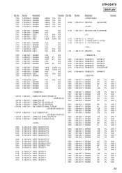
C104 C105 C106 C107 C108 Part No. FB100 Part No. No. No. Description 1-127-880-31 CERAMIC 1-127-880-31 CERAMIC 1-127-880-31 CERAMIC 1-127-880-31 CERAMIC 1-127-880-31 CERAMIC 0.022uF ... 4.7K 5% 1/4W F 10K 5% 1/4W 330 5% 1/4W 470 5% 1/4W F 680 5% 1/4W F 1K 5% 1/4W F 1.5K 5% 1/4W F 2.2K 5% 1/4W F 150 5% 1/4W F 100 5% 1/4W 100 5% 1/4W 100 5% 1/4W 29 STR-DE475 DISPLAY Ref.
C104 C105 C106 C107 C108 Part No. FB100 Part No. No. No. Description 1-127-880-31 CERAMIC 1-127-880-31 CERAMIC 1-127-880-31 CERAMIC 1-127-880-31 CERAMIC 1-127-880-31 CERAMIC 0.022uF ... 4.7K 5% 1/4W F 10K 5% 1/4W 330 5% 1/4W 470 5% 1/4W F 680 5% 1/4W F 1K 5% 1/4W F 1.5K 5% 1/4W F 2.2K 5% 1/4W F 150 5% 1/4W F 100 5% 1/4W 100 5% 1/4W 100 5% 1/4W 29 STR-DE475 DISPLAY Ref.
Service Manual
Page 30
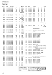
No. STR-DE475 DISPLAY Ref. R058 R062 R064 R065 R098 Part No. Description 1-247-807-31 CARBON 100 1-247-807-31 CARBON 100 1-247-807-31 CARBON 100 1-247-807-31 CARBON 100 1-247-807-31 ... S100 S101 S102 S103 S104 S105 S106 S107 S110 S111 S112 S113 S114 S115 S116 S117 S118 S120 S121 S122 S123 S124 S125 S126 S127 Part No.
No. STR-DE475 DISPLAY Ref. R058 R062 R064 R065 R098 Part No. Description 1-247-807-31 CARBON 100 1-247-807-31 CARBON 100 1-247-807-31 CARBON 100 1-247-807-31 CARBON 100 1-247-807-31 ... S100 S101 S102 S103 S104 S105 S106 S107 S110 S111 S112 S113 S114 S115 S116 S117 S118 S120 S121 S122 S123 S124 S125 S126 S127 Part No.


