
Limited Warranty (U.S. Only)
Page 1
...number has been altered or removed from state to service the Product. This warranty is valid only in the United States. This warranty gives you specific legal rights, and you , or for service assistance or resolution of a service problem, or for all labor charges. 2. After the warranty ... servicer or dealer nearest you may not apply to you. 4-557-173-02 General Stereo/Hifi Components/Tape Decks ® CD Players/Mini Disc Players/Audio Systems Hifi Audio LIMITED WARRANTY Sony Electronics Inc. ("Sony") warrants this Product is within 90 days of the date of sale, the limitation...
...number has been altered or removed from state to service the Product. This warranty is valid only in the United States. This warranty gives you specific legal rights, and you , or for service assistance or resolution of a service problem, or for all labor charges. 2. After the warranty ... servicer or dealer nearest you may not apply to you. 4-557-173-02 General Stereo/Hifi Components/Tape Decks ® CD Players/Mini Disc Players/Audio Systems Hifi Audio LIMITED WARRANTY Sony Electronics Inc. ("Sony") warrants this Product is within 90 days of the date of sale, the limitation...
Operating Instructions (Receiver Component)
Page 3
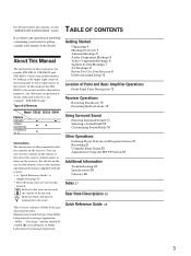
...do the task. Check your nearest Sony dealer. Indicates hints and tips for models STR-DE535, STR-DE435 and STR-SE491. "Dolby ," "Pro Logic" and the double-D symbol a are used for illustration purposes, any question or problem concerning your receiver, please consult your model number ... Troubleshooting 24 Specifications 25 Glossary 26 Index 27 Rear Panel Descriptions 28 Quick Reference Guide 29 3 Getting Started Unpacking 4 Hookup Overview 4 Antenna Hookups 5 Audio Component Hookups 5 Video Component Hookups 6 Speaker System Hookups 7 AC Hookups 9 Before You Use Your Receiver 9 Dolby ...
...do the task. Check your nearest Sony dealer. Indicates hints and tips for models STR-DE535, STR-DE435 and STR-SE491. "Dolby ," "Pro Logic" and the double-D symbol a are used for illustration purposes, any question or problem concerning your receiver, please consult your model number ... Troubleshooting 24 Specifications 25 Glossary 26 Index 27 Rear Panel Descriptions 28 Quick Reference Guide 29 3 Getting Started Unpacking 4 Hookup Overview 4 Antenna Hookups 5 Audio Component Hookups 5 Video Component Hookups 6 Speaker System Hookups 7 AC Hookups 9 Before You Use Your Receiver 9 Dolby ...
Operating Instructions (Receiver Component)
Page 5
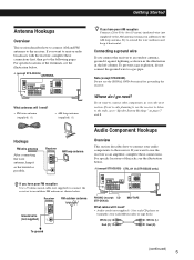
...complete these connections first, then go on to "Speaker System Hookups" on pages 7 and 8. Receiver ANTENNA FM outdoor antenna AM Ground wire (not supplied) y COAXIAL FM 75Ω To ground PHONO (except CD STR-DE435) MD/TAPE What cables will I need ? • Audio cords (not supplied) (1 ...as shown below. y (except STR-DE435) ANTENNA What antennas will I go to the next section. Note (except STR-DE435) Do not use the receiver to listen to the radio, go next? For specific locations of the terminals, see the illustration below . For specific locations of the jacks, see ...
...complete these connections first, then go on to "Speaker System Hookups" on pages 7 and 8. Receiver ANTENNA FM outdoor antenna AM Ground wire (not supplied) y COAXIAL FM 75Ω To ground PHONO (except CD STR-DE435) MD/TAPE What cables will I need ? • Audio cords (not supplied) (1 ...as shown below. y (except STR-DE435) ANTENNA What antennas will I go to the next section. Note (except STR-DE435) Do not use the receiver to listen to the radio, go next? For specific locations of the terminals, see the illustration below . For specific locations of the jacks, see ...
Operating Instructions (Receiver Component)
Page 6
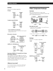
...components to TV programs or video tapes. 6 For specific locations of the jacks, see the illustration below. 5.1 CH/DVD MONITOR (except STR-SE491) TV/SAT VIDEO What cables will I go next? CD player Receiver L R AUDIO IN CD CD player OUTPUT LINE L R Turntable (except STR-DE435) Receiver L R AUDIO IN PHONO Turntable OUTPUT LINE L R...recorder or Tape deck OUTPUT INPUT LINE LINE L R CONTROL A1 II (STR-DE535 only) Receiver CTRL A1 II CD player, MD recorder or Tape deck CTRL A1 II If you have a CONTROL A1 II-compatible Sony CD player, MD recorder or tape deck Use a CONTROL A1 II cord ...
...components to TV programs or video tapes. 6 For specific locations of the jacks, see the illustration below. 5.1 CH/DVD MONITOR (except STR-SE491) TV/SAT VIDEO What cables will I go next? CD player Receiver L R AUDIO IN CD CD player OUTPUT LINE L R Turntable (except STR-DE435) Receiver L R AUDIO IN PHONO Turntable OUTPUT LINE L R...recorder or Tape deck OUTPUT INPUT LINE LINE L R CONTROL A1 II (STR-DE535 only) Receiver CTRL A1 II CD player, MD recorder or Tape deck CTRL A1 II If you have a CONTROL A1 II-compatible Sony CD player, MD recorder or tape deck Use a CONTROL A1 II cord ...

Operating Instructions (Receiver Component)
Page 7
...to match the speaker cord to the appropriate terminal on to the next section to + and - Hookups Front speakers Front speaker (R) Receiver FRONT R L A A B R B L Front speaker (L) * STR-DE535 and STR-DE435 only Where do I need ? • Audio cable (not supplied) (1 for each 5.1 CH/DVD FRONT and REAR jacks) White...on the components: + to connect the speakers. (continued) 7 For specific locations of the cord about 2/3 inch (15 mm). If the cords are required. DVD player/AC-3 decoder What cable will I need ? Receiver FRONT 5.1 CH/DVD REAR CENTER L R WOOFER VIDEO IN Dolby ...
...to match the speaker cord to the appropriate terminal on to the next section to + and - Hookups Front speakers Front speaker (R) Receiver FRONT R L A A B R B L Front speaker (L) * STR-DE535 and STR-DE435 only Where do I need ? • Audio cable (not supplied) (1 for each 5.1 CH/DVD FRONT and REAR jacks) White...on the components: + to connect the speakers. (continued) 7 For specific locations of the cord about 2/3 inch (15 mm). If the cords are required. DVD player/AC-3 decoder What cable will I need ? Receiver FRONT 5.1 CH/DVD REAR CENTER L R WOOFER VIDEO IN Dolby ...
Operating Instructions (Receiver Component)
Page 14
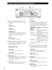
...to remote signals sent from the 2 way remote. (page 23) * STR-DE535 only. !• Press the following indications. You will be able to...FM band. For details, see page 19). @¡ DIMMER button Press this button. MEMORY button Press to set the display at any one of the four center modes (page 10) REAR GAIN Increase the range of rear speakers by 5 dB (page 11) AUTO FUNCTION* Specify whether or not Sony...21). FM MODE button If "STEREO" flashes in the display and the FM stereo reception is improved. NAME button Press to make specific settings (see "Receiving Broadcasts" starting ...
...to remote signals sent from the 2 way remote. (page 23) * STR-DE535 only. !• Press the following indications. You will be able to...FM band. For details, see page 19). @¡ DIMMER button Press this button. MEMORY button Press to set the display at any one of the four center modes (page 10) REAR GAIN Increase the range of rear speakers by 5 dB (page 11) AUTO FUNCTION* Specify whether or not Sony...21). FM MODE button If "STEREO" flashes in the display and the FM stereo reception is improved. NAME button Press to make specific settings (see "Receiving Broadcasts" starting ...
Operating Instructions (Receiver Component)
Page 25
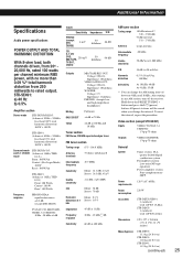
... Mass (Approx.) STR-DE535: 11.1 kg (24 lb 6 oz) STR-DE435: 11.0 kg (24 lb 3 oz) STR-SE491: 11.2 kg (24 lb 9 oz) (continued) 25 Additional Information Specifications Audio power specifications POWER OUTPUT AND TOTAL...70 Hz ±8 dB at 100 Hz and 10 kHz Tuner section FM Stereo, FM/AM superheterodyne tuner FM tuner section Tuning range 87.5 - 108.0 MHz Antenna terminals 75 ohms, ...receiver. Hold down the PRESET TUNING + button and press the 1/u (power) button. To reset the interval, repeat the procedure. STR-SE491: a) 40 Hz b) 0.5% Amplifier section Stereo mode STR-DE535/DE435...
... Mass (Approx.) STR-DE535: 11.1 kg (24 lb 6 oz) STR-DE435: 11.0 kg (24 lb 3 oz) STR-SE491: 11.2 kg (24 lb 9 oz) (continued) 25 Additional Information Specifications Audio power specifications POWER OUTPUT AND TOTAL...70 Hz ±8 dB at 100 Hz and 10 kHz Tuner section FM Stereo, FM/AM superheterodyne tuner FM tuner section Tuning range 87.5 - 108.0 MHz Antenna terminals 75 ohms, ...receiver. Hold down the PRESET TUNING + button and press the 1/u (power) button. To reset the interval, repeat the procedure. STR-SE491: a) 40 Hz b) 0.5% Amplifier section Stereo mode STR-DE535/DE435...

Operating Instructions (Receiver Component)
Page 26
... monaural sound. • 3 STEREO mode Select 3 STEREO mode if you have front and rear speakers and a small center speaker. Design and specifications are heard. The acoustics where ... Information Supplied accessories FM wire antenna (1) AM loop antenna (1) Remote commander (remote) (1) (see page 4) LR6 (size-AA) batteries (3) (STR-DE535 only) R6 (size-AA) batteries (2) (STR-DE435/SE491 only) &#...speaker (L) Rear speaker (R) Dolby Pro Logic Surround As one method of the receiver. Furthermore, since it is independently provided. Compared with an expanded frequency range and ...
... monaural sound. • 3 STEREO mode Select 3 STEREO mode if you have front and rear speakers and a small center speaker. Design and specifications are heard. The acoustics where ... Information Supplied accessories FM wire antenna (1) AM loop antenna (1) Remote commander (remote) (1) (see page 4) LR6 (size-AA) batteries (3) (STR-DE535 only) R6 (size-AA) batteries (2) (STR-DE435/SE491 only) &#...speaker (L) Rear speaker (R) Dolby Pro Logic Surround As one method of the receiver. Furthermore, since it is independently provided. Compared with an expanded frequency range and ...