
Limited Warranty (U.S. Only)
Page 1
... Information Services Center 1-800-222-7669 or visit the Sony Web Site: www.sony.com For an accessory or part not available from the Product. This warranty does not cover customer instruction, installation, set up adjustments or signal reception problems. This warranty does not cover ... period of two (2) year from state to state. 4-557-173-02 General Stereo/Hifi Components/Tape Decks ® CD Players/Mini Disc Players/Audio Systems Hifi Audio LIMITED WARRANTY Sony Electronics Inc. ("Sony") warrants this Product is determined to be presented to obtain warranty service. After the...
... Information Services Center 1-800-222-7669 or visit the Sony Web Site: www.sony.com For an accessory or part not available from the Product. This warranty does not cover customer instruction, installation, set up adjustments or signal reception problems. This warranty does not cover ... period of two (2) year from state to state. 4-557-173-02 General Stereo/Hifi Components/Tape Decks ® CD Players/Mini Disc Players/Audio Systems Hifi Audio LIMITED WARRANTY Sony Electronics Inc. ("Sony") warrants this Product is determined to be presented to obtain warranty service. After the...

Service Manual
Page 1
...(with no sound output. FM STEREO FM-AM RECEIVER 9-928-896-12 2002B1600-1 © 2002.02 Sony Corporation Home Audio Company Published by Sony Engineering Corporation STR-DB830/DB930/V929X SERVICE MANUAL Ver 1.1 2002. 02 Photo : STR-DB930 (BLACK model) US Model STR-DB930/DB830 Canadian Model STR-DB930 AEP Model STR-DB930/DB830 E Model Australian Model STR-DB930 Chinese Model STR-V929X Manufactured under license...
...(with no sound output. FM STEREO FM-AM RECEIVER 9-928-896-12 2002B1600-1 © 2002.02 Sony Corporation Home Audio Company Published by Sony Engineering Corporation STR-DB830/DB930/V929X SERVICE MANUAL Ver 1.1 2002. 02 Photo : STR-DB930 (BLACK model) US Model STR-DB930/DB830 Canadian Model STR-DB930 AEP Model STR-DB930/DB830 E Model Australian Model STR-DB930 Chinese Model STR-V929X Manufactured under license...
Service Manual
Page 3
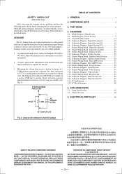
... 4-8. Schematic Diagram Video Section 41 4-19. Front Panel Section 62 5-2. NE REMPLACER CES COMPOSANTS QUE PAR DES PIÈSES SONY DONT LES NUMÉROS SONT DONNÉS DANS CE MANUEL OU DANS LES SUPPÉMENTS PUBLIÉS PAR... for this job. 3. Schematic Diagram Digital Section(2/3 15 4-6. Schematic Diagram Power Section 37 4-17. SAFETY-RELATED COMPONENT WARNING!! A) To Exposed Metal Parts on Set 0.15µF 1.5kΩ AC voltmeter (0.75V) TABLE OF CONTENTS 1. Block Diagram Main Section 7 4-2. Schematic Diagram Digital Section(1/3 13 4-5. Printed Wiring ...
... 4-8. Schematic Diagram Video Section 41 4-19. Front Panel Section 62 5-2. NE REMPLACER CES COMPOSANTS QUE PAR DES PIÈSES SONY DONT LES NUMÉROS SONT DONNÉS DANS CE MANUEL OU DANS LES SUPPÉMENTS PUBLIÉS PAR... for this job. 3. Schematic Diagram Digital Section(2/3 15 4-6. Schematic Diagram Power Section 37 4-17. SAFETY-RELATED COMPONENT WARNING!! A) To Exposed Metal Parts on Set 0.15µF 1.5kΩ AC voltmeter (0.75V) TABLE OF CONTENTS 1. Block Diagram Main Section 7 4-2. Schematic Diagram Digital Section(1/3 13 4-5. Printed Wiring ...
Service Manual
Page 4
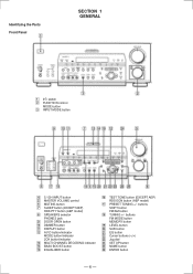
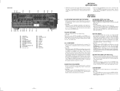
... button MEMORY button !ª LEVEL button @º SUR button @¡ EQ button @™ Cursor buttons () @£ Jog dial @¢ SET UP button @∞ NAME button @§ ENTER button - 4 - buttons SHIFT button FM/AM button !• TUNNIG +/- Identifying the Parts Front Panel SECTION 1 GENERAL 1 1/u switch 2 FUNCTION control MODE button 3 INPUT MODE button 4 5.1CH...
... button MEMORY button !ª LEVEL button @º SUR button @¡ EQ button @™ Cursor buttons () @£ Jog dial @¢ SET UP button @∞ NAME button @§ ENTER button - 4 - buttons SHIFT button FM/AM button !• TUNNIG +/- Identifying the Parts Front Panel SECTION 1 GENERAL 1 1/u switch 2 FUNCTION control MODE button 3 INPUT MODE button 4 5.1CH...
Service Manual
Page 5
...Model only) * This mode is returned. Turn off , and the demonstration resumes if the power [1/u] button is used , the receiver scans the broadcasts that can be received by the broken data line or defective soldering. * Procedure While pressing the SETUP, LEVEL and SUR buttons, press the POWER button to... turn on the main power. Errors can be caused by tuner, and sets up the broadcasts. When servicing the DIGITAL...
...Model only) * This mode is returned. Turn off , and the demonstration resumes if the power [1/u] button is used , the receiver scans the broadcasts that can be received by the broken data line or defective soldering. * Procedure While pressing the SETUP, LEVEL and SUR buttons, press the POWER button to... turn on the main power. Errors can be caused by tuner, and sets up the broadcasts. When servicing the DIGITAL...
Service Manual
Page 36
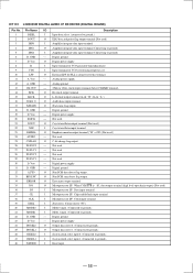
... terminal 23 EMPHA O Emphasis monitor output terminal ("H" = ON) (Not used .) 22 XIN I /F. Chip enable/latch input terminal 38 CLK I Microprocessor I /F RECEIVER (DIGITAL BOARD) Pin No. IC1101 LC89055W DIGITAL AUDIO I /F. GND - VDD - Not used . 30 D. GND - Not used . 29 F3/P3/C3 -...GND - VDD O Digital power supply 8 R I Input terminal for VCO generator band adjustment 9 V IN I Input terminal for VCO self running frequency set 10 LPF O External LPF for PLL is "H", data output terminal (high level open drain output) (Not used . 27 F1/P1/C1 - Analog...
... terminal 23 EMPHA O Emphasis monitor output terminal ("H" = ON) (Not used .) 22 XIN I /F. Chip enable/latch input terminal 38 CLK I Microprocessor I /F RECEIVER (DIGITAL BOARD) Pin No. IC1101 LC89055W DIGITAL AUDIO I /F. GND - VDD - Not used . 30 D. GND - Not used . 29 F3/P3/C3 -...GND - VDD O Digital power supply 8 R I Input terminal for VCO generator band adjustment 9 V IN I Input terminal for VCO self running frequency set 10 LPF O External LPF for PLL is "H", data output terminal (high level open drain output) (Not used . 27 F1/P1/C1 - Analog...

Service Manual
Page 44
...1-125-900-12 ELECT C804 1-125-895-11 ELECT 47uF 15000uF 12000uF 15000uF 12000uF 20% 25V 20% 71V (DB930/V929X) 20% 71V (DB830) 20% 71V (DB930/V929X) 20% 71V (DB830) D901 D902 D903 D904 D905 8-719-053-18 8-719-053-18 8-719-053-18 8-719-053-18 8-719-801-78 DIODE DIODE... may be anticipated when ordering these items. • CAPACITORS: uF: µF • RESISTORS All resistors are in the diagrams or the components used on the set. • -XX, -X mean standardized parts, so they may have some difference from the original one. • Items marked "*" are not stocked since they are ...
...1-125-900-12 ELECT C804 1-125-895-11 ELECT 47uF 15000uF 12000uF 15000uF 12000uF 20% 25V 20% 71V (DB930/V929X) 20% 71V (DB830) 20% 71V (DB930/V929X) 20% 71V (DB830) D901 D902 D903 D904 D905 8-719-053-18 8-719-053-18 8-719-053-18 8-719-053-18 8-719-801-78 DIODE DIODE... may be anticipated when ordering these items. • CAPACITORS: uF: µF • RESISTORS All resistors are in the diagrams or the components used on the set. • -XX, -X mean standardized parts, so they may have some difference from the original one. • Items marked "*" are not stocked since they are ...


