

Limited Warranty (U.S. Only)
Page 1
... prepaid, in material or workmanship as fuses or batteries). 4-557-173-02 General Stereo/Hifi Components/Tape Decks ® CD Players/Mini Disc Players/Audio Systems Hifi Audio LIMITED WARRANTY Sony Electronics Inc. ("Sony") warrants this Product is determined to be presented to obtain warranty service. After the warranty period, you must pay the labor charges to any part of sale or receipted invoice which vary from your...
... prepaid, in material or workmanship as fuses or batteries). 4-557-173-02 General Stereo/Hifi Components/Tape Decks ® CD Players/Mini Disc Players/Audio Systems Hifi Audio LIMITED WARRANTY Sony Electronics Inc. ("Sony") warrants this Product is determined to be presented to obtain warranty service. After the warranty period, you must pay the labor charges to any part of sale or receipted invoice which vary from your...
Operating Instructions
Page 1
Record the serial number in the space provided below. Model No. SONY Refer to these numbers whenever you call upon your Sony dealer regarding this manual thoroughly and retain it for future reference. SONY® FM Stereo/FM-AM Receiver 3-769-919-22 (1) Operating Instructions Before operating the unit, please read this product. Owner's Record The model and serial numbers are located at the rear. STR-AV700 Serial No.
Record the serial number in the space provided below. Model No. SONY Refer to these numbers whenever you call upon your Sony dealer regarding this manual thoroughly and retain it for future reference. SONY® FM Stereo/FM-AM Receiver 3-769-919-22 (1) Operating Instructions Before operating the unit, please read this product. Owner's Record The model and serial numbers are located at the rear. STR-AV700 Serial No.
Operating Instructions
Page 2
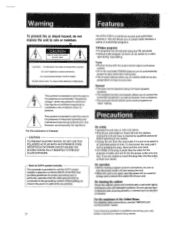
Tuner • Precise tuning with mild detergent solution. Precautions On safety • Operate the unit only on a video tape during tape editing. If you have it checked by grasping the plug. REFER SERVICING TO QUALIFIED SERVICE PERSONNEL. Note to rain or moisture. General • The tone can be adjusted using the FM simulcast. • Various audio program sources can be added on 120 V AC, 60 Hz...
Tuner • Precise tuning with mild detergent solution. Precautions On safety • Operate the unit only on a video tape during tape editing. If you have it checked by grasping the plug. REFER SERVICING TO QUALIFIED SERVICE PERSONNEL. Note to rain or moisture. General • The tone can be adjusted using the FM simulcast. • Various audio program sources can be added on 120 V AC, 60 Hz...

Operating Instructions
Page 3
... notes Audio connection diagram Connecting the speakers Connecting the AM antenna Connecting the FM antenna Connecting the antenna ground Connecting a turntable system Connecting a CD player Connecting a tape deck Connecting a DAT (Digital Audio Tape) deck Connecting the system for remote control Connecting the AC power VCR and TV connection diagram Connecting a VCR Connecting a monitor TV Parts identification Remote commander RM-U80 ',. ei otit::,i*Oyer:34 .k't 0 Audio adjustment Receiving FMIAM broadcasts Direct tuning Automatic searching stations (Auto-preset) Tuning in a preset station...
... notes Audio connection diagram Connecting the speakers Connecting the AM antenna Connecting the FM antenna Connecting the antenna ground Connecting a turntable system Connecting a CD player Connecting a tape deck Connecting a DAT (Digital Audio Tape) deck Connecting the system for remote control Connecting the AC power VCR and TV connection diagram Connecting a VCR Connecting a monitor TV Parts identification Remote commander RM-U80 ',. ei otit::,i*Oyer:34 .k't 0 Audio adjustment Receiving FMIAM broadcasts Direct tuning Automatic searching stations (Auto-preset) Tuning in a preset station...

Operating Instructions
Page 5
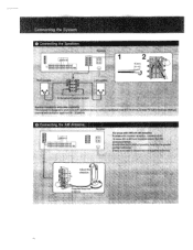
....page le O • t all , first making sure that the SYSTEM POWER switch is turned off. • The cable connectors should be connected last of all § debt 1:0 P$Oe • • oO ePige$ To tne second speaker ayetedi to the individual connection diagram. zo, e Connection Note.s • The power cord should be fully inserted into the jacks. A loose connection may cause hum and noise.
....page le O • t all , first making sure that the SYSTEM POWER switch is turned off. • The cable connectors should be connected last of all § debt 1:0 P$Oe • • oO ePige$ To tne second speaker ayetedi to the individual connection diagram. zo, e Connection Note.s • The power cord should be fully inserted into the jacks. A loose connection may cause hum and noise.
Operating Instructions
Page 6
.... Connecting the AM Antenna Receiver @C) ao- Speaker Impedance andpower Catii6itifY This receiver fs designed to work best with Speakers having nominalirnpedatide from S to 16ohms,at eater:J.70 Watt::mfrilniutnRMSpet cliannel with troubled recebtton, connect'a 6-to the AM antenna terrnInat : • Extetid this Out'et doors if possible,keepfirg-the great portkort herizontai. (there isno 'need t6disoormect theSuppired Adjust the kft direction. tar, tJ Supplied loop-free antenna...
.... Connecting the AM Antenna Receiver @C) ao- Speaker Impedance andpower Catii6itifY This receiver fs designed to work best with Speakers having nominalirnpedatide from S to 16ohms,at eater:J.70 Watt::mfrilniutnRMSpet cliannel with troubled recebtton, connect'a 6-to the AM antenna terrnInat : • Extetid this Out'et doors if possible,keepfirg-the great portkort herizontai. (there isno 'need t6disoormect theSuppired Adjust the kft direction. tar, tJ Supplied loop-free antenna...

Operating Instructions
Page 12
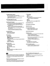
Parts identification Refer to the pages indicated in • for details. FM TUNING LEVEL button (r) FM mode button Qi Display window eio MUSIC INDEX selector and indicator ID 5 BAND GRAPHIC EQUALIZER 4 Remote control sensor SYSTEM POWER switch HEADPHONES jack (stereo phone jack) SPEAKERS selectors MUSIC INDEX ON/OFF buttons (r) flE) TAPE 2 MONITOR button and indicator MUSIC INDEX MEMORY button (I) 12 IsI T CP= I J
Parts identification Refer to the pages indicated in • for details. FM TUNING LEVEL button (r) FM mode button Qi Display window eio MUSIC INDEX selector and indicator ID 5 BAND GRAPHIC EQUALIZER 4 Remote control sensor SYSTEM POWER switch HEADPHONES jack (stereo phone jack) SPEAKERS selectors MUSIC INDEX ON/OFF buttons (r) flE) TAPE 2 MONITOR button and indicator MUSIC INDEX MEMORY button (I) 12 IsI T CP= I J
Operating Instructions
Page 15
... time you can operate one side of the deck TV buttons VOL: Adjusts the TV sound level. In such cases, clear the modes using this remote commander. • SHUFFLE and PGM modes of some CD players cannot be cleared by this button, the music index category changes as that set this selector to a tape in the "B" deck of a double-deck unit. IA SYSTEM POWER OFF button Turns off . STOP: Stops record play . CH: Selects...
... time you can operate one side of the deck TV buttons VOL: Adjusts the TV sound level. In such cases, clear the modes using this remote commander. • SHUFFLE and PGM modes of some CD players cannot be cleared by this button, the music index category changes as that set this selector to a tape in the "B" deck of a double-deck unit. IA SYSTEM POWER OFF button Turns off . STOP: Stops record play . CH: Selects...

Operating Instructions
Page 16
... not symmetrical. SUBSONIC L. (1') t To change the relative strength of the right and left speaker output Adjust BALANCE to a stereo source. Press again to achieve the desired effect. Aud o Adjustment For getting the optimum sound, you can adjust volume and sound quality using the functions below. Sound Quality Adjustment To equalize the sound Slide the equalizer controls up or down to disengage the subsonic. Press again to turn off the effect. MUTING...
... not symmetrical. SUBSONIC L. (1') t To change the relative strength of the right and left speaker output Adjust BALANCE to a stereo source. Press again to achieve the desired effect. Aud o Adjustment For getting the optimum sound, you can adjust volume and sound quality using the functions below. Sound Quality Adjustment To equalize the sound Slide the equalizer controls up or down to disengage the subsonic. Press again to turn off the effect. MUTING...

Operating Instructions
Page 17
... below). 5 Adjust the volume. Caution When the interval is preset to 1,610 kHz.) Enter the correct frequency. AM 530 to 10 kHz. To reset the AM tuning interval, repeat the above steps from the beginning. OS:CArAsriPTCOVItiNfi41401,4444ssrti r.": r.441701MitttoMte1.4, . If the frequency figures flash in any AM station. 2 Turn off the unit. 3 Depress SYSTEM POWER again while pressing the "+" STATION SCAN button. However...
... below). 5 Adjust the volume. Caution When the interval is preset to 1,610 kHz.) Enter the correct frequency. AM 530 to 10 kHz. To reset the AM tuning interval, repeat the above steps from the beginning. OS:CArAsriPTCOVItiNfi41401,4444ssrti r.": r.441701MitttoMte1.4, . If the frequency figures flash in any AM station. 2 Turn off the unit. 3 Depress SYSTEM POWER again while pressing the "+" STATION SCAN button. However...

Operating Instructions
Page 18
... LOW. Each time you want to receive Press FM MODE. Station Scan Tuning SYSTEM POWER--.-ON . To stop searching Press TUNER. When an FM stereo program is heard in monaural, but the reception will change the frequency. The STEREO indicator goes out (the sound is noisy or hard to tune in . You can tune the station in a Preset Station - Receiving FNIJAM Broadcasts • • • • • SYSTEM POWER-.ON TUNINO LEVEL...
... LOW. Each time you want to receive Press FM MODE. Station Scan Tuning SYSTEM POWER--.-ON . To stop searching Press TUNER. When an FM stereo program is heard in monaural, but the reception will change the frequency. The STEREO indicator goes out (the sound is noisy or hard to tune in . You can tune the station in a Preset Station - Receiving FNIJAM Broadcasts • • • • • SYSTEM POWER-.ON TUNINO LEVEL...

Operating Instructions
Page 19
... index you have chosen will blink.) a: 5 Repeat steps 3 and 4 for each of stations you want to assign to the indexes. 6 Press MEMORY again. (The MEMORY indicator will disappear.) Note This function cannot be stored in music indexes. Categorizing Preset Stations Using the Music Index You can be used while the unit is in direct tuning mode. Only preset stations can divide preset stations into categories, ROCK, JAZZ...
... index you have chosen will blink.) a: 5 Repeat steps 3 and 4 for each of stations you want to assign to the indexes. 6 Press MEMORY again. (The MEMORY indicator will disappear.) Note This function cannot be stored in music indexes. Categorizing Preset Stations Using the Music Index You can be used while the unit is in direct tuning mode. Only preset stations can divide preset stations into categories, ROCK, JAZZ...

Operating Instructions
Page 20
... station number in the music index of the index you have selected. Use that number while the music index function is not lit, press MUSIC INDEX ON/OFF. (A MUSIC INDEX indicator will 0 0 light up .) 3 Select the music index you want. (The indicator of the station you want You can tune in the station directly. 1 Press TUNER. 2 Select the music index you want. 3 Select the preset station number with the numeric buttons. 4 Press ENTER. If the music...
... station number in the music index of the index you have selected. Use that number while the music index function is not lit, press MUSIC INDEX ON/OFF. (A MUSIC INDEX indicator will 0 0 light up .) 3 Select the music index you want. (The indicator of the station you want You can tune in the station directly. 1 Press TUNER. 2 Select the music index you want. 3 Select the preset station number with the numeric buttons. 4 Press ENTER. If the music...
Operating Instructions
Page 21
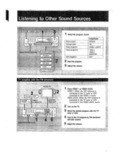
... VHF antenna is connected to the TV tuner or VCR connected to Other Sound Sources SYSTEM POWER--.ON .liLl, 11118 1 I me 0.)) .. t SPEAK5RS Aor8, Turntable system, CD player Tape deck DAT deck VCR 1 ITV tuner or VCR 2 TV reception with this receiver. 5 Adjust the volume. T_. FUNCTION: PHONO CD VIDEO 1, 2ICDV TAPE 1, TAPE 2 MONITOR DAT 310 C." 1 Press VIDEO 1 or VIDEO 2/CDV. VIDEO 1: When the VHF antenna is connected to the TV tuner or VCR connected to the VIDEO 2JCDV inputs. 2 Turn on...
... VHF antenna is connected to the TV tuner or VCR connected to Other Sound Sources SYSTEM POWER--.ON .liLl, 11118 1 I me 0.)) .. t SPEAK5RS Aor8, Turntable system, CD player Tape deck DAT deck VCR 1 ITV tuner or VCR 2 TV reception with this receiver. 5 Adjust the volume. T_. FUNCTION: PHONO CD VIDEO 1, 2ICDV TAPE 1, TAPE 2 MONITOR DAT 310 C." 1 Press VIDEO 1 or VIDEO 2/CDV. VIDEO 1: When the VHF antenna is connected to the TV tuner or VCR connected to the VIDEO 2JCDV inputs. 2 Turn on...
Operating Instructions
Page 22
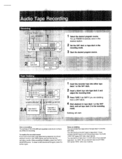
Audio Tape Recording Recording SYSTEM POWER-ON Select SPEAKERS A or 888 CI m Cl I=1=L:1 O Td DATor ' ,TAPE1REC OUT DAT or tape deck Turntable system CD player VCR 1 Select the desired program source. Tape Dubbing SYSTEM POWER-ON 1-Sellact A o* • c,1,01 Ho ,=,.... - , . You can monitor the recording results. Note on recording The settings of the VOLUME and equalizer controls do not have connected a tape deck having separate record and playback heeds to the TAPE 2 jacks, you...
Audio Tape Recording Recording SYSTEM POWER-ON Select SPEAKERS A or 888 CI m Cl I=1=L:1 O Td DATor ' ,TAPE1REC OUT DAT or tape deck Turntable system CD player VCR 1 Select the desired program source. Tape Dubbing SYSTEM POWER-ON 1-Sellact A o* • c,1,01 Ho ,=,.... - , . You can monitor the recording results. Note on recording The settings of the VOLUME and equalizer controls do not have connected a tape deck having separate record and playback heeds to the TAPE 2 jacks, you...
Operating Instructions
Page 23
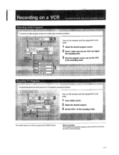
... VIDEO 2 inputs. Note on recording The VOLUME and equalizer settings on the receiver do not have any effect on the recording. g 1 Select the desired program source. 2 Insert a video tape into the VCR and adjust the reconiing level. 3 Start the program source and set the VCR to the recording mode. re, Y: nar You cannot record on a VCR connected to be used . 1 , . Recording on a VCR To operate the VCR, refer to its instruction manual...
... VIDEO 2 inputs. Note on recording The VOLUME and equalizer settings on the receiver do not have any effect on the recording. g 1 Select the desired program source. 2 Insert a video tape into the VCR and adjust the reconiing level. 3 Start the program source and set the VCR to the recording mode. re, Y: nar You cannot record on a VCR connected to be used . 1 , . Recording on a VCR To operate the VCR, refer to its instruction manual...
Operating Instructions
Page 24
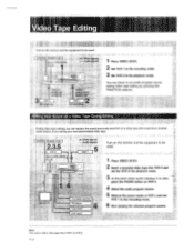
SYSTEM POWER-.ON $1#ct SPEAKERS A or . 4.414rdeoilOnats tAutidSii2n4S lig VIDEO 2. SYSTEM POWER-ON I '." ,• s .a.yrdi,fO t0gnalS VCR 1 Turn on the receiver and the equipment to be used . 1 Press VIDEO 2ICDV. 2 Insert a recorded video tape into VCR 2 and set VCR 1 to an audio program source during video tape editing by pressing the FUNCTION selector. You can replace the sound previously recorded on a video tape with sound from VCR 1 to VCR 2. I a ---- '"'" I • - 2,36 . _VeR2...
SYSTEM POWER-.ON $1#ct SPEAKERS A or . 4.414rdeoilOnats tAutidSii2n4S lig VIDEO 2. SYSTEM POWER-ON I '." ,• s .a.yrdi,fO t0gnalS VCR 1 Turn on the receiver and the equipment to be used . 1 Press VIDEO 2ICDV. 2 Insert a recorded video tape into VCR 2 and set VCR 1 to an audio program source during video tape editing by pressing the FUNCTION selector. You can replace the sound previously recorded on a video tape with sound from VCR 1 to VCR 2. I a ---- '"'" I • - 2,36 . _VeR2...
Operating Instructions
Page 25
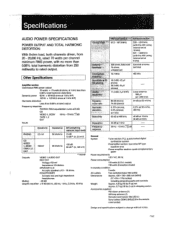
... CD VIDEO 1, 2/CDV 10 Hz - 70 kHz `1._-(1) dB TAPE 1, 2 DAT Inputs Sensitivity Impedance S/N (weighting network, input level) PHONO 2.5 mV 50 kilohms 74 dB 72 dB* (A. 2.5 mV) . General System Tuner section: PLL quartz-locked digital synthesizer system Preamplifier section: low-noise NF type equalizer amp Power amplifier section: quasi-complementary SEPP Power requirements 120 V AC, 60 Hz Power consumption 125 watts (U.S.A. Other Specifications Amplifier section Continuous RMS power output 75 watts + 75 watts (8 ohms, at...
... CD VIDEO 1, 2/CDV 10 Hz - 70 kHz `1._-(1) dB TAPE 1, 2 DAT Inputs Sensitivity Impedance S/N (weighting network, input level) PHONO 2.5 mV 50 kilohms 74 dB 72 dB* (A. 2.5 mV) . General System Tuner section: PLL quartz-locked digital synthesizer system Preamplifier section: low-noise NF type equalizer amp Power amplifier section: quasi-complementary SEPP Power requirements 120 V AC, 60 Hz Power consumption 125 watts (U.S.A. Other Specifications Amplifier section Continuous RMS power output 75 watts + 75 watts (8 ohms, at...
Operating Instructions
Page 26
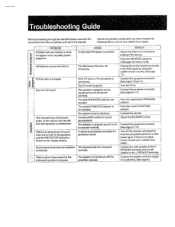
... nearest Sony dealer. The speaker or program source is received. There is not turned on . Press the correct FUNCTION selector. I Adjust the antenna or connect an external FM antenna. The TV is lack of the speakers, and the PROTECTOR indication flickers in the display window. REMEDY I VCR, TV tuner or TV connection is reversed. program Picture does not appear. correctly. Adjust the BALANCE control. PROBLEM ' - One channel does not transmit audio, or the volume...
... nearest Sony dealer. The speaker or program source is received. There is not turned on . Press the correct FUNCTION selector. I Adjust the antenna or connect an external FM antenna. The TV is lack of the speakers, and the PROTECTOR indication flickers in the display window. REMEDY I VCR, TV tuner or TV connection is reversed. program Picture does not appear. correctly. Adjust the BALANCE control. PROBLEM ' - One channel does not transmit audio, or the volume...

Operating Instructions
Page 27
... type. Replace the batteries with alcohol. The audio components are dirty. Connect the ground wire to a TV set or a fluorescent light. and the commander head. 27 If both are loose. Place the connecting cords in a location away from a transformer or motor, and at the same time, separate the TV from a TV set . The plugs and jacks are too close to the antenna ground terminal...
... type. Replace the batteries with alcohol. The audio components are dirty. Connect the ground wire to a TV set or a fluorescent light. and the commander head. 27 If both are loose. Place the connecting cords in a location away from a transformer or motor, and at the same time, separate the TV from a TV set . The plugs and jacks are too close to the antenna ground terminal...

