
Operating Instructions
Page 1
Owner's Record The model and serial numbers are located at the rear. Record the serial number in the space provided below. Refer to these numbers whenever you call upon your Sony dealer regarding this manual thoroughly and retain it for future reference. Model No. STR-AV500 Serial No. SONY ti 0 © 1988 by Sony Corporation A,I)'CVID CONTROL CENTL:5 SONY FM Stereo/FM-AM Receiver 3-769-887-22 (1) Operating Instructions Before operating the unit, please read this product.
Owner's Record The model and serial numbers are located at the rear. Record the serial number in the space provided below. Refer to these numbers whenever you call upon your Sony dealer regarding this manual thoroughly and retain it for future reference. Model No. STR-AV500 Serial No. SONY ti 0 © 1988 by Sony Corporation A,I)'CVID CONTROL CENTL:5 SONY FM Stereo/FM-AM Receiver 3-769-887-22 (1) Operating Instructions Before operating the unit, please read this product.
Operating Instructions
Page 2
...please consult your unit. It makes an ideal container to the point of cable entry as practical. 2 The STR-AV500 is not to remotely control the connected equipment as well as the receiver. The unit allows you to switch easily between a variety of audio/video programs. General • TV programs ... On repacking Do not throw away the carton and the packing material. If you are unable to extend the useful life of your nearest Sony dealer. Warning Features To prevent fire or shock hazard, do not expose the unit to the presence of important operating and maintenance (servicing)...
...please consult your unit. It makes an ideal container to the point of cable entry as practical. 2 The STR-AV500 is not to remotely control the connected equipment as well as the receiver. The unit allows you to switch easily between a variety of audio/video programs. General • TV programs ... On repacking Do not throw away the carton and the packing material. If you are unable to extend the useful life of your nearest Sony dealer. Warning Features To prevent fire or shock hazard, do not expose the unit to the presence of important operating and maintenance (servicing)...

Operating Instructions
Page 3
... power VCR and TV connection diagram Connecting a VCR Connecting a monitor TV Parts identification Remote commander RM-U80 Using Your Receiver Audio adjustment Receiving FM/AM broadcasts Tuning in a station directly (Direct access tuning) Tuning in an FM station automatically (Automatic tuning) ...Manual tuning) Memorizing a station (Memory preset) Tuning in a preset station (Preset tuning) Listening to program sources other than broadcasts Receiving a TV program with FM simulcast Recording on an audio tape Recording Tape dubbing Recording on a VCR _Recording audio programs Recording TV ...
... power VCR and TV connection diagram Connecting a VCR Connecting a monitor TV Parts identification Remote commander RM-U80 Using Your Receiver Audio adjustment Receiving FM/AM broadcasts Tuning in a station directly (Direct access tuning) Tuning in an FM station automatically (Automatic tuning) ...Manual tuning) Memorizing a station (Memory preset) Tuning in a preset station (Preset tuning) Listening to program sources other than broadcasts Receiving a TV program with FM simulcast Recording on an audio tape Recording Tape dubbing Recording on a VCR _Recording audio programs Recording TV ...
Operating Instructions
Page 6
... an 8-ohm load from 8 to disconnect the supplied antenna.) Adjust the direction. 3:00 0 4r1 75() Supplied loop- O O 2 15 mm O O I Speaker impedance and power capability This receiver is no need to 16 ohms, at rated 55 watts minimum RMS per channel with speakers having nominal impedance from 20 - 20,000 Hz. Connecting...
... an 8-ohm load from 8 to disconnect the supplied antenna.) Adjust the direction. 3:00 0 4r1 75() Supplied loop- O O 2 15 mm O O I Speaker impedance and power capability This receiver is no need to 16 ohms, at rated 55 watts minimum RMS per channel with speakers having nominal impedance from 20 - 20,000 Hz. Connecting...

Operating Instructions
Page 7
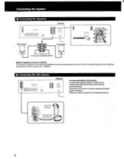
When an outdoor antenna is installed, be sure to ANTENNA ground terminal (h). O Connecting the FM antenna I® O OO O O O O OO OOO OOOO OO OOO 1=3 Receiver U1 L-J rFor normal use Supplied ribbon antenna (or 300-ohm twin-lead) 3Eiar) 75Q 4J 0 AM For higher quality sound 0 AM 75-ohm coaxial cable (optional) O Connecting the Antenna Ground To prevent hum, connect the ground wire to connect the ground wire for lightning protection. • Connecting a Turntable System @do@ 00i INC %MIL O OOO OO O @@ OOO OO O @@ 700 Receiver Turntable system tc1 A 7
When an outdoor antenna is installed, be sure to ANTENNA ground terminal (h). O Connecting the FM antenna I® O OO O O O O OO OOO OOOO OO OOO 1=3 Receiver U1 L-J rFor normal use Supplied ribbon antenna (or 300-ohm twin-lead) 3Eiar) 75Q 4J 0 AM For higher quality sound 0 AM 75-ohm coaxial cable (optional) O Connecting the Antenna Ground To prevent hum, connect the ground wire to connect the ground wire for lightning protection. • Connecting a Turntable System @do@ 00i INC %MIL O OOO OO O @@ OOO OO O @@ 700 Receiver Turntable system tc1 A 7

Operating Instructions
Page 8
... POO ... 000 000 m. 0 8 O O OO O @ aele (Di OOO@aOKDO! mien- mom+ . Connecting the System O Connecting a CD Player la @C.@ @l@ O:@I l i Doo O Connecting a Tape Deck :0 7 T- 0 pppO O @@@@ @@@@ 0OO0'0O0O A TAPE Receive RK-C74 toline outputs Tape deck wastee* Ike _ eirorik =D-----1 -'- © • to line inputs O Connecting a DAT (Digital Audio Tape) Deck...
... POO ... 000 000 m. 0 8 O O OO O @ aele (Di OOO@aOKDO! mien- mom+ . Connecting the System O Connecting a CD Player la @C.@ @l@ O:@I l i Doo O Connecting a Tape Deck :0 7 T- 0 pppO O @@@@ @@@@ 0OO0'0O0O A TAPE Receive RK-C74 toline outputs Tape deck wastee* Ike _ eirorik =D-----1 -'- © • to line inputs O Connecting a DAT (Digital Audio Tape) Deck...

Operating Instructions
Page 9
... wall outlet (1) Connecting the AC Power tip O O OO O O O O O OOOOloO6Oo CD@ OO Receiver AC outlets Connect the AC power cord of each piece of equipment connected to these outlets. 9 0 Connecting the... outlet of 7Turntable system the recevier -r-- 410 to the AC outlet IN of the receiver OUT CD player IN OUT *to a wall outlet To control the equipment connected to the AC outlet on the... receiver does not exceed 100 watts. eser to a wall outlet Caution Be careful that you can turn ...
... wall outlet (1) Connecting the AC Power tip O O OO O O O O O OOOOloO6Oo CD@ OO Receiver AC outlets Connect the AC power cord of each piece of equipment connected to these outlets. 9 0 Connecting the... outlet of 7Turntable system the recevier -r-- 410 to the AC outlet IN of the receiver OUT CD player IN OUT *to a wall outlet To control the equipment connected to the AC outlet on the... receiver does not exceed 100 watts. eser to a wall outlet Caution Be careful that you can turn ...

Operating Instructions
Page 10
... and playback) (For details see below) iup iup lop • iup 0 0 0 0 O O C) @C,••• 0 00 ©0••• I=1 • Receiver ErE C-J oill Connecting a VCR _a open a 0 600 © 0 @ 0000 00066 Receiver RIF to a wall outlet 'DEO 2 VIDEO I OUT IN to the second VCR to video input VMC-1S condZi= to audio...
... and playback) (For details see below) iup iup lop • iup 0 0 0 0 O O C) @C,••• 0 00 ©0••• I=1 • Receiver ErE C-J oill Connecting a VCR _a open a 0 600 © 0 @ 0000 00066 Receiver RIF to a wall outlet 'DEO 2 VIDEO I OUT IN to the second VCR to video input VMC-1S condZi= to audio...

Operating Instructions
Page 11
® Connecting a Monitor TV Receiver O OOO ion O C00iO11• 0O OO el@ 'OO @ @ 1 1=1_ gb m®gym II 0 CD 0 I OH VMC-1S Monitor TV to video input mICL__,Iz. momy 11
® Connecting a Monitor TV Receiver O OOO ion O C00iO11• 0O OO el@ 'OO @ @ 1 1=1_ gb m®gym II 0 CD 0 I OH VMC-1S Monitor TV to video input mICL__,Iz. momy 11

Operating Instructions
Page 15
...-: Selects a lower preset number. 121 FUNCTION selectors 3 INDEX select buttons (These buttons do not operate on the STR-AV500.) [1] TV buttons VOL: Adjusts the TV sound level. STOP: Stops record play. • CD buttons P ... : Starts play ▪ Stops play N4/1"4.4: AMS (Automatic Music Sensor) PGM: Program play . If a Sony 8 mm VCR is usable for a CD player equipped with "control-S", you can operate one side of the ... the CD player. AUDIO: Turns the power of the receiver on and off E] SYSTEM POWER OFF button Turns off the power of the receiver, TV, VCR 1, 2 E TARE and VTR selector ...
...-: Selects a lower preset number. 121 FUNCTION selectors 3 INDEX select buttons (These buttons do not operate on the STR-AV500.) [1] TV buttons VOL: Adjusts the TV sound level. STOP: Stops record play. • CD buttons P ... : Starts play ▪ Stops play N4/1"4.4: AMS (Automatic Music Sensor) PGM: Program play . If a Sony 8 mm VCR is usable for a CD player equipped with "control-S", you can operate one side of the ... the CD player. AUDIO: Turns the power of the receiver on and off E] SYSTEM POWER OFF button Turns off the power of the receiver, TV, VCR 1, 2 E TARE and VTR selector ...

Operating Instructions
Page 17
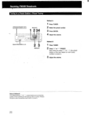
...1: FM 108.00 MHz Example 2: AM 1350 kHz I AM kHz Tuning in the display window The entered number is outside the receiver's frequency range (FM 87.5 to enter the frequency. (See examples below). 5 Adjust the volume. However, if you have changed ... B. 1 Press TUNER. 2 Press FM. 3 Press "+" or "-" TUNING. When an FM stereo program is received, automatic tuning automatically stops. 4 Adjust the volume. When sweeping does not stop sweeping Press TUNER. I Receiving FM/AM Broadcasts Tuning in -Direct Access Tuning." "+": Starts frequency-ascending sweep from 87.50 MHz. -": Starts ...
...1: FM 108.00 MHz Example 2: AM 1350 kHz I AM kHz Tuning in the display window The entered number is outside the receiver's frequency range (FM 87.5 to enter the frequency. (See examples below). 5 Adjust the volume. However, if you have changed ... B. 1 Press TUNER. 2 Press FM. 3 Press "+" or "-" TUNING. When an FM stereo program is received, automatic tuning automatically stops. 4 Adjust the volume. When sweeping does not stop sweeping Press TUNER. I Receiving FM/AM Broadcasts Tuning in -Direct Access Tuning." "+": Starts frequency-ascending sweep from 87.50 MHz. -": Starts ...

Operating Instructions
Page 18
... station. 2 Press SYSTEM POWER to turn off the unit. 3 Depress SYSTEM POWER again while pressing the "+" TUNING button. To use the receiver where the frequency allocation system is pressed, the frequency will be sure to 10 kHz. To change by 10 kHz. To reset the AM ..., repeat the above steps. 18 Caution When the interval is preset to preset the stations again. "+": Starts Manual Tuning from 1610 kHz. Receiving FM!AM Broadcasts Tuning in an AM Station Manually-Manual Tuning When you have memorized will change the frequency continuously, keep the button pressed. ...
... station. 2 Press SYSTEM POWER to turn off the unit. 3 Depress SYSTEM POWER again while pressing the "+" TUNING button. To use the receiver where the frequency allocation system is pressed, the frequency will be sure to 10 kHz. To change by 10 kHz. To reset the AM ..., repeat the above steps. 18 Caution When the interval is preset to preset the stations again. "+": Starts Manual Tuning from 1610 kHz. Receiving FM!AM Broadcasts Tuning in an AM Station Manually-Manual Tuning When you have memorized will change the frequency continuously, keep the button pressed. ...
Operating Instructions
Page 20
Receiving FM/AM Broadcasts Tuning in . 20 Notes on Method B If you press "+" (or "-"), the preset station of number. Release the Qutton when the desired preset ...
Receiving FM/AM Broadcasts Tuning in . 20 Notes on Method B If you press "+" (or "-"), the preset station of number. Release the Qutton when the desired preset ...

Operating Instructions
Page 21
.... 1 Press VIDEO 1 or VIDEO 2. is connected to the TV tuner or VCR connected to the VIDEO 1 inputs. FUNCTION PHONO CD VIDEO 1, 2 TAPE DAT Receiving a TV Program with this receiver. 5 Adjust the volume. 2 VIDEO 2: When the VHF antenna is ening o • rogram ources I er an Broadcasts I SYSTEM POWER ON 0 00 000 0100 0100...
.... 1 Press VIDEO 1 or VIDEO 2. is connected to the TV tuner or VCR connected to the VIDEO 1 inputs. FUNCTION PHONO CD VIDEO 1, 2 TAPE DAT Receiving a TV Program with this receiver. 5 Adjust the volume. 2 VIDEO 2: When the VHF antenna is ening o • rogram ources I er an Broadcasts I SYSTEM POWER ON 0 00 000 0100 0100...
Operating Instructions
Page 23
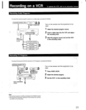
... not have any effect on a VCR To operate the VCR, refer to its instruction manual. CD player Tape deck 4*---1 DAT deck Turn on the receiver and the equipment to be used . 1 Select the desired program source. 2 Insert a video tape into the VCR and adjust the recording level 3 ...proceed as follows: SYSTEM POWER-ON 2 VCR 2 VIDEO 2 VIDEO 1N/AUDIO IN 3 VCR 1 VIDEO 1 VIDEO OUT/ AUDIO OUT 89999 = TTT ® Turn on the receiver and the equipment to be used . 1 Press VIDEO 2/CDV. 2 Select the desired program. 3 Set the VCR 1 in the recording mode. Select SPEAKERS A or B. Turntable ...
... not have any effect on a VCR To operate the VCR, refer to its instruction manual. CD player Tape deck 4*---1 DAT deck Turn on the receiver and the equipment to be used . 1 Select the desired program source. 2 Insert a video tape into the VCR and adjust the recording level 3 ...proceed as follows: SYSTEM POWER-ON 2 VCR 2 VIDEO 2 VIDEO 1N/AUDIO IN 3 VCR 1 VIDEO 1 VIDEO OUT/ AUDIO OUT 89999 = TTT ® Turn on the receiver and the equipment to be used . 1 Press VIDEO 2/CDV. 2 Select the desired program. 3 Set the VCR 1 in the recording mode. Select SPEAKERS A or B. Turntable ...
Operating Instructions
Page 24
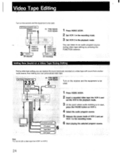
... POWER-O 2,3 VCR 2 Select SPEAKERS A or S. L Video Signals Audio signals VCR 1 1 4 Monitor TV Turntable system CD player Tape deck DAT deck Turn on the receiver and the equipment to be used . 1 Press VIDEO 2/CDV. 2 Insert a recorded video tape into VCR 2 and set the VCR in the playback mode. 3 At ... tape editing, you can listen to an audio program source during video tape editing by pressing the FUNCTION selector. Video Tape Editing Turn on the receiver and the equipment to be used . Video signals Audio signals VIDEO 2 VIDEO IN/ AUDIO IN VCR 2 (for playack) VIDEO 1 VIDEO OUT/...
... POWER-O 2,3 VCR 2 Select SPEAKERS A or S. L Video Signals Audio signals VCR 1 1 4 Monitor TV Turntable system CD player Tape deck DAT deck Turn on the receiver and the equipment to be used . 1 Press VIDEO 2/CDV. 2 Insert a recorded video tape into VCR 2 and set the VCR in the playback mode. 3 At ... tape editing, you can listen to an audio program source during video tape editing by pressing the FUNCTION selector. Video Tape Editing Turn on the receiver and the equipment to be used . Video signals Audio signals VIDEO 2 VIDEO IN/ AUDIO IN VCR 2 (for playack) VIDEO 1 VIDEO OUT/...
Operating Instructions
Page 25
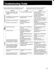
...TV tuner or TV connection is not connected correctly. The speaker or program source equipment is not correct. The correct FUNCTION selector is received. One channel does not transmit audio, or the volume from the speakers The speakers are pressed. The BALANCE control is reversed. Broadcast... FM MODE button to minimum. There is lack of your nearest Sony dealer. The AM tuning interval is unbalanced. Connect the equipment correctly. (See pages 10 and 11.) The TV is obscure. Turn off the receiver, eliminate the short-circuit problem and turn on . Connect the ...
...TV tuner or TV connection is not connected correctly. The speaker or program source equipment is not correct. The correct FUNCTION selector is received. One channel does not transmit audio, or the volume from the speakers The speakers are pressed. The BALANCE control is reversed. Broadcast... FM MODE button to minimum. There is lack of your nearest Sony dealer. The AM tuning interval is unbalanced. Connect the equipment correctly. (See pages 10 and 11.) The TV is obscure. Turn off the receiver, eliminate the short-circuit problem and turn on . Connect the ...
Operating Instructions
Page 26
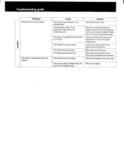
Troubleshooting guide Amplifier PROBLEM Severe hum or noise is not grounded. The receiver is heard. Place the connecting cords in a location away from a transformer or motor, and at the same time, separate the TV from a TV set . Make ...
Troubleshooting guide Amplifier PROBLEM Severe hum or noise is not grounded. The receiver is heard. Place the connecting cords in a location away from a transformer or motor, and at the same time, separate the TV from a TV set . Make ...


