Operating Instructions
Page 1
SONY 3-759-251-22(2) Home Theater . Adive Speaker System Operating Instructions SA-VAI
SONY 3-759-251-22(2) Home Theater . Adive Speaker System Operating Instructions SA-VAI
Operating Instructions
Page 3
... into the outlet, contact your system that does not block the rear ventilation holes. Depending on your nearest Sony dealer. 3 Place the speakers at a location with adequate air circulation, and in a place subject to direct sunlight, excessive dust, mechanical...supplied accessories 7 Inserting the batteries into the remote commander 7 Hooking Up the System 7 Positioning the speaker system 7 Notes on speaker connection 7 Connecting the speakers to video equipment 8 Basic Operations Enjoying Surround Sound 10 Adjusting the Audio 12 Advanced Operations Enjoying ...
... into the outlet, contact your system that does not block the rear ventilation holes. Depending on your nearest Sony dealer. 3 Place the speakers at a location with adequate air circulation, and in a place subject to direct sunlight, excessive dust, mechanical...supplied accessories 7 Inserting the batteries into the remote commander 7 Hooking Up the System 7 Positioning the speaker system 7 Notes on speaker connection 7 Connecting the speakers to video equipment 8 Basic Operations Enjoying Surround Sound 10 Adjusting the Audio 12 Advanced Operations Enjoying ...
Operating Instructions
Page 4
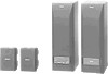
...following patents: US number 3,959,590; Additionally licensed under license from a program source. Furthermore, by the SA-VAI (see page 14). * Manufactured under one , "Tall-boy" style speaker system features a freestanding tower design styled to your video equipment and easy operation with an audio connecting cord...your TV simply with the supplied remote commander, ensuring maximum enjoyment of the true home theater sound this mode, the SA-VAI turns on the left speaker. cu,• V alir es- You can obtain full surround sound that gives you can also connect your TV. ...
...following patents: US number 3,959,590; Additionally licensed under license from a program source. Furthermore, by the SA-VAI (see page 14). * Manufactured under one , "Tall-boy" style speaker system features a freestanding tower design styled to your video equipment and easy operation with an audio connecting cord...your TV simply with the supplied remote commander, ensuring maximum enjoyment of the true home theater sound this mode, the SA-VAI turns on the left speaker. cu,• V alir es- You can obtain full surround sound that gives you can also connect your TV. ...
Operating Instructions
Page 5
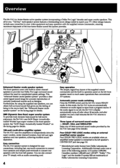
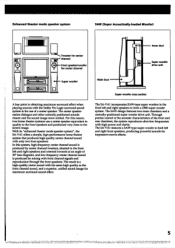
...the front and rear chambers, the system reproduces ultra-low frequencies with only two front speakers. Front speaker/woofer o for center channel e - With its "enhanced theater mode speaker system", the SA-VAI offers a simple, high-performance home theater system that produces high-quality center ... and a centrally-positioned super woofer drive unit. The SA-VAI incorporates SAW-type super woofers in the front left and right speakers and oriented inwards at an angle of a center speaker. Enhanced theater mode speaker system SAW (Super Acoustically-loaded Woofer) cr. The ...
...the front and rear chambers, the system reproduces ultra-low frequencies with only two front speakers. Front speaker/woofer o for center channel e - With its "enhanced theater mode speaker system", the SA-VAI offers a simple, high-performance home theater system that produces high-quality center ... and a centrally-positioned super woofer drive unit. The SA-VAI incorporates SAW-type super woofers in the front left and right speakers and oriented inwards at an angle of a center speaker. Enhanced theater mode speaker system SAW (Super Acoustically-loaded Woofer) cr. The ...
Operating Instructions
Page 6
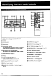
...buttons (pages 12 and 13) [E, DELAY TIME button (page 13) REAR LEVEL +/- EE ER MONK 'LIt 7 VON 1 1 SOW! EE IE ACTIVE SPEAKERe SONY I For details, refer to an AC outlet and the system is connected to the page number(s) indicated in STANDBY mode. ID DOLBY PRO LOGIC ON... 11) E STD (standard) LEVEL button (page 13) IE DISPLAY button (page 11) iF MASTER VOL (VOLUME) +/- Identifying the Parts and Controls Left-speaker operation panel/remote commander CJID3 EEO E 9 .4, BBBQ8t100" i PRO LOOICA HiTimmimm WON VON suoilpfte C•KIC, WOE wpm. button(s) (pages 11 and 12...
...buttons (pages 12 and 13) [E, DELAY TIME button (page 13) REAR LEVEL +/- EE ER MONK 'LIt 7 VON 1 1 SOW! EE IE ACTIVE SPEAKERe SONY I For details, refer to an AC outlet and the system is connected to the page number(s) indicated in STANDBY mode. ID DOLBY PRO LOGIC ON... 11) E STD (standard) LEVEL button (page 13) IE DISPLAY button (page 11) iF MASTER VOL (VOLUME) +/- Identifying the Parts and Controls Left-speaker operation panel/remote commander CJID3 EEO E 9 .4, BBBQ8t100" i PRO LOOICA HiTimmimm WON VON suoilpfte C•KIC, WOE wpm. button(s) (pages 11 and 12...
Operating Instructions
Page 7
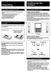
.... Location of the rear speakers Place the rear speakers to the right so that the following accessories are present: • Front L/R speaker connecting cord, 3.5 m (1) • Rear speaker connecting cord, 10 m (2) • Audio connecting cord, 1.5 m (1) • Remote commander RM-VA1 (1) • Sony batteries SUM-3 (NS) ... accessories After unpacking, check that the center channel tweeters angle inwards toward the center of the SA-VAI. Positioning the speaker system Location of the front speakers To obtain high sound quality and a proper sound image from the TV. 1 Open the cover...
.... Location of the rear speakers Place the rear speakers to the right so that the following accessories are present: • Front L/R speaker connecting cord, 3.5 m (1) • Rear speaker connecting cord, 10 m (2) • Audio connecting cord, 1.5 m (1) • Remote commander RM-VA1 (1) • Sony batteries SUM-3 (NS) ... accessories After unpacking, check that the center channel tweeters angle inwards toward the center of the SA-VAI. Positioning the speaker system Location of the front speakers To obtain high sound quality and a proper sound image from the TV. 1 Open the cover...
Operating Instructions
Page 8
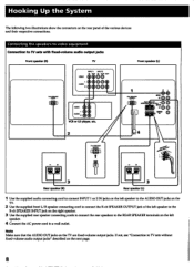
... the AUDIO OUT jacks on the next page. 8 SPEAKER OUIPU'r O O O IIIIPEONCE SE aEuNcetv 2 I AUDIO R VCR or LD player, etc. 2 Front speaker (L) lid. I 4 1- !I :4 R I °M*, R RO, SPENCER OUTPUT 0:774 1-0":41 O p_74 07:4I 3 Rear speaker (R) 3 • Rear speaker (L) Use the supplied audio connecting cord to connect INPUT... on the rear panel of the left speaker to the R-ch SPEAKER INPUT jack on the right speaker. 3 Use the supplied rear speaker connecting cords to connect the rear speakers to the REAR SPEAKER terminals on the left speaker to the AUDIO OUT jacks on the TV...
... the AUDIO OUT jacks on the next page. 8 SPEAKER OUIPU'r O O O IIIIPEONCE SE aEuNcetv 2 I AUDIO R VCR or LD player, etc. 2 Front speaker (L) lid. I 4 1- !I :4 R I °M*, R RO, SPENCER OUTPUT 0:774 1-0":41 O p_74 07:4I 3 Rear speaker (R) 3 • Rear speaker (L) Use the supplied audio connecting cord to connect INPUT... on the rear panel of the left speaker to the R-ch SPEAKER INPUT jack on the right speaker. 3 Use the supplied rear speaker connecting cords to connect the rear speakers to the REAR SPEAKER terminals on the left speaker to the AUDIO OUT jacks on the TV...
Operating Instructions
Page 9
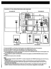
... MAR 0 11---,1 I II R On AUDIO 0 VCR or LD player, etc. 4 WO SPEAKER OUTPUT MI6 6 171 Pwc'0500 5 Rear speaker (R) 5 Rear speaker (L) 1 Connect the INPUT 1 or 2 IN jacks on the left speaker to the AUDIO OUT jacks on the video equipment. 2 Connect the VIDEO OUT jack on the ...4 Use the supplied front L/R speaker connecting cord to connect the R-ch SPEAKER OUTPUT jack on the left speaker to the R-ch SPEAKER INPUT jack on the right speaker. 5 Use the supplied rear speaker connecting cord to connect the rear speakers to the REAR SPEAKER terminals on the left speaker. 6 Connect the AC power...
... MAR 0 11---,1 I II R On AUDIO 0 VCR or LD player, etc. 4 WO SPEAKER OUTPUT MI6 6 171 Pwc'0500 5 Rear speaker (R) 5 Rear speaker (L) 1 Connect the INPUT 1 or 2 IN jacks on the left speaker to the AUDIO OUT jacks on the video equipment. 2 Connect the VIDEO OUT jack on the ...4 Use the supplied front L/R speaker connecting cord to connect the R-ch SPEAKER OUTPUT jack on the left speaker to the R-ch SPEAKER INPUT jack on the right speaker. 5 Use the supplied rear speaker connecting cord to connect the rear speakers to the REAR SPEAKER terminals on the left speaker. 6 Connect the AC power...
Operating Instructions
Page 10
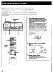
... produces superb theater-like sound when playing movies or sound sources bearing the "00i or "DOLBY STEREO" logo. INPUT INPUT 1 I INPUT 2 I =1 ED O. 5 ACTIVE SPEAKER MANN SONY Press POWER on the POWER switch lights up . For details on the POWER switch turns red and the... speaker system returns to READY mode. MOUNE( MUTING - 0 MASTIF VOL 0 • 5 4 S.WOOFER ON/OFF MODE 2 MUTra =, O °En .6 =I =I rEiliti I=I 0 MOP ass I=I 0 THE I _) Operation panel Remote ...
... produces superb theater-like sound when playing movies or sound sources bearing the "00i or "DOLBY STEREO" logo. INPUT INPUT 1 I INPUT 2 I =1 ED O. 5 ACTIVE SPEAKER MANN SONY Press POWER on the POWER switch lights up . For details on the POWER switch turns red and the... speaker system returns to READY mode. MOUNE( MUTING - 0 MASTIF VOL 0 • 5 4 S.WOOFER ON/OFF MODE 2 MUTra =, O °En .6 =I =I rEiliti I=I 0 MOP ass I=I 0 THE I _) Operation panel Remote ...
Operating Instructions
Page 11
.../OFF MOOS PRO LOGIC ON/OFF MODE Operation panel Remote commander Note The DOLBY PRO LOGIC MODE button is operable only when an external center speaker is output.
.../OFF MOOS PRO LOGIC ON/OFF MODE Operation panel Remote commander Note The DOLBY PRO LOGIC MODE button is operable only when an external center speaker is output.
Operating Instructions
Page 12
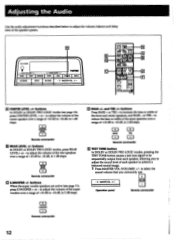
... E TEST TONE button In DOLBY or DOLBY PRO LOGIC modes, pressing the TEST TONE button causes a test tone signal to be sequentially output from each speaker to -10 dB, in 1 dB steps. =1 CENTER LEVEL CD Remote commander E REAR LEVEL +/- l=) EAR LREVEL CD Remote commander im S.WOOFER +/- buttons Press...10 dB to -10 dB, in 2 dB steps. (=1 BASS =I S.W00FER = Remote commander 12 to adjust the volume of the rear speakers over a range of the speaker system. Adjusting the Audio Use the audio adjustment functions described below to -10 dB, in 1 dB steps. buttons In DOLBY or DOLBY PRO ...
... E TEST TONE button In DOLBY or DOLBY PRO LOGIC modes, pressing the TEST TONE button causes a test tone signal to be sequentially output from each speaker to -10 dB, in 1 dB steps. =1 CENTER LEVEL CD Remote commander E REAR LEVEL +/- l=) EAR LREVEL CD Remote commander im S.WOOFER +/- buttons Press...10 dB to -10 dB, in 2 dB steps. (=1 BASS =I S.W00FER = Remote commander 12 to adjust the volume of the rear speakers over a range of the speaker system. Adjusting the Audio Use the audio adjustment functions described below to -10 dB, in 1 dB steps. buttons In DOLBY or DOLBY PRO ...
Operating Instructions
Page 13
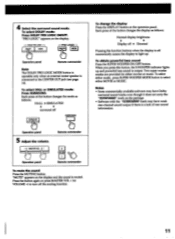
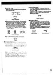
...1=3 Remote commander 4 Press TEST TONE to turn on the display. Press DELAY TIME to turn off , pressing the STD LEVEL button causes the super woofer speakers to choose one of the sound in the DOLBY PRO LOGIC modes (see page 14) for sources with CENTER LEVEL +/-, REAR LEVEL +/- TEST TONE =i E...delay time to their factory settings (the STD LEVEL indicator lights up), and again to restore the previous volume level of the sound from each speaker in the following delay times:15, 20, 25, and 30 ms. The selected delay time appears on automatically. and BALANCE L/R to your ...
...1=3 Remote commander 4 Press TEST TONE to turn on the display. Press DELAY TIME to turn off , pressing the STD LEVEL button causes the super woofer speakers to choose one of the sound in the DOLBY PRO LOGIC modes (see page 14) for sources with CENTER LEVEL +/-, REAR LEVEL +/- TEST TONE =i E...delay time to their factory settings (the STD LEVEL indicator lights up), and again to restore the previous volume level of the sound from each speaker in the following delay times:15, 20, 25, and 30 ms. The selected delay time appears on automatically. and BALANCE L/R to your ...
Operating Instructions
Page 14
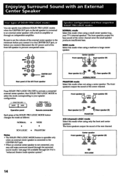
...available through an independent amplifier. Front speaker (L) Front speaker (R) Rear speaker (L) CiD te.,+Rear speaker (R) PHANTOM 3CH (channel) LOGIC mode Select this mode when not using a medium to your TV's internal speaker). Center speaker Front speaker (L)i Front speaker (R) l=1*. R L Speaker configurations and their respective DOLBY PRO ... when the CENTER OUT jack on the left speaker is connected to an external center speaker with a built-in amplifier or through SA-VAT's "enhanced theater mode speaker system". The front speakers output the bass sound of the center channel ...
...available through an independent amplifier. Front speaker (L) Front speaker (R) Rear speaker (L) CiD te.,+Rear speaker (R) PHANTOM 3CH (channel) LOGIC mode Select this mode when not using a medium to your TV's internal speaker). Center speaker Front speaker (L)i Front speaker (R) l=1*. R L Speaker configurations and their respective DOLBY PRO ... when the CENTER OUT jack on the left speaker is connected to an external center speaker with a built-in amplifier or through SA-VAT's "enhanced theater mode speaker system". The front speakers output the bass sound of the center channel ...
Operating Instructions
Page 15
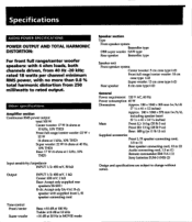
... INPUT 1/2: 450 mV, 1 kil Center: 650 mV, 2 kit Rear: Accept only supplied rear speakers SS-SR11 R-ch: Accept only SA-VA1 R-ch speaker with supplied front L/R speaker connecting cord Tone control Front/center Super woofer Bass: ±10 dB at 100 Hz Treble: &#...(28 lb 9 oz) Rear: 800 g/pc (1 lb 12 oz) Supplied accessories Front L/R speaker connecting cord, 3.5 m (1) Rear speaker connecting cord, 10 m (2) Audio connecting cord, 1.5 m (1) Remote commander RM-VAI (1) Sony batteries SUM-3 (NS) (2) Design and specifications are subject to rated output. Specifications AUDIO POWER ...
... INPUT 1/2: 450 mV, 1 kil Center: 650 mV, 2 kit Rear: Accept only supplied rear speakers SS-SR11 R-ch: Accept only SA-VA1 R-ch speaker with supplied front L/R speaker connecting cord Tone control Front/center Super woofer Bass: ±10 dB at 100 Hz Treble: &#...(28 lb 9 oz) Rear: 800 g/pc (1 lb 12 oz) Supplied accessories Front L/R speaker connecting cord, 3.5 m (1) Rear speaker connecting cord, 10 m (2) Audio connecting cord, 1.5 m (1) Remote commander RM-VAI (1) Sony batteries SUM-3 (NS) (2) Design and specifications are subject to rated output. Specifications AUDIO POWER ...
Operating Instructions
Page 16
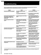
... the plug into the power outlet. No sound or very low level sound is heard from the rear speakers in these checks, consult your nearest Sony dealer. Cause The speaker terminals are run down. A program source with REAR LEVEL +/- (see page 12). Sound is an ...obstruction between the remote commander and the SA-VAl. There is not output from the center speaker. Remove the obstruction. Trouble No sound...
... the plug into the power outlet. No sound or very low level sound is heard from the rear speakers in these checks, consult your nearest Sony dealer. Cause The speaker terminals are run down. A program source with REAR LEVEL +/- (see page 12). Sound is an ...obstruction between the remote commander and the SA-VAl. There is not output from the center speaker. Remove the obstruction. Trouble No sound...


