Operating Instructions
Page 1
SONY 3-759-251-22(2) Home Theater . Adive Speaker System Operating Instructions SA-VAI
SONY 3-759-251-22(2) Home Theater . Adive Speaker System Operating Instructions SA-VAI
Operating Instructions
Page 2
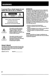
... with the instructions, may be determined by one or more of electric shock to which can radiate radio frequency energy and, if not installed and used in this manual could void your Sony dealer regarding this equipment. These limits are cautioned that to persons. CAUTION You are designed to constitute a risk of the following measures: - Model No. SA-VA1 Serial No...
... with the instructions, may be determined by one or more of electric shock to which can radiate radio frequency energy and, if not installed and used in this manual could void your Sony dealer regarding this equipment. These limits are cautioned that to persons. CAUTION You are designed to constitute a risk of the following measures: - Model No. SA-VA1 Serial No...
Operating Instructions
Page 3
...the Parts and Controls 6 Left-speaker operation panel/remote commander 6 Getting Started Unpacking 7 Checking the supplied accessories 7 Inserting the batteries into the remote commander 7 Hooking Up the System 7 Positioning the speaker system 7 Notes on speaker connection 7 Connecting the speakers to video equipment 8 Basic Operations Enjoying Surround Sound 10 Adjusting the Audio 12 Advanced Operations Enjoying Surround Sound with an External Center Speaker 14 Four types of DOLBY PRO LOGIC modes 14 Speaker configurations and their respective DOLBY PRO LOGIC modes...
...the Parts and Controls 6 Left-speaker operation panel/remote commander 6 Getting Started Unpacking 7 Checking the supplied accessories 7 Inserting the batteries into the remote commander 7 Hooking Up the System 7 Positioning the speaker system 7 Notes on speaker connection 7 Connecting the speakers to video equipment 8 Basic Operations Enjoying Surround Sound 10 Adjusting the Audio 12 Advanced Operations Enjoying Surround Sound with an External Center Speaker 14 Four types of DOLBY PRO LOGIC modes 14 Speaker configurations and their respective DOLBY PRO LOGIC modes...
Operating Instructions
Page 4
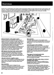
... speakers come with the supplied remote commander, ensuring maximum enjoyment of surround sound modes - This "enhanced theater mode speaker system" provides a clear center-signal sound image for details. Furthermore, by the SA-VAI (see page 14). * Manufactured under one -touch connectors to connect front speakers and simple push-terminals to provide true Dolby Pro Logic surround sound without the need for details. 100-watt multi-drive amplifier system The SA-VAI uses five amplifiers...
... speakers come with the supplied remote commander, ensuring maximum enjoyment of surround sound modes - This "enhanced theater mode speaker system" provides a clear center-signal sound image for details. Furthermore, by the SA-VAI (see page 14). * Manufactured under one -touch connectors to connect front speakers and simple push-terminals to provide true Dolby Pro Logic surround sound without the need for details. 100-watt multi-drive amplifier system The SA-VAI uses five amplifiers...
Operating Instructions
Page 5
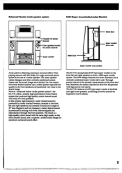
... control of the acoustic characteristics of a center speaker. In this reason, true home theater systems use of the front and rear chambers, the system reproduces ultra-low frequencies with only two front speakers. The SA-VAI features a SAW-type super woofer in the front left and right front speakers, producing powerful sounds for maximum surround sound effect. C=Er"••Tweeter for center channel Inner duct Super woofer drive unit .4 - Enhanced theater mode speaker...
... control of the acoustic characteristics of a center speaker. In this reason, true home theater systems use of the front and rear chambers, the system reproduces ultra-low frequencies with only two front speakers. The SA-VAI features a SAW-type super woofer in the front left and right front speakers, producing powerful sounds for maximum surround sound effect. C=Er"••Tweeter for center channel Inner duct Super woofer drive unit .4 - Enhanced theater mode speaker...
Operating Instructions
Page 6
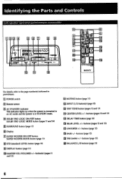
... IE ACTIVE SPEAKERe SONY I For details, refer to an AC outlet and the system is in parentheses. El POWER switch M Remote sensor El AC STANDBY indicator This indicator lights up when the system is connected to the page number(s) indicated in STANDBY mode. buttons (page 12) it BASS +/- buttons (page 12) THE (treble) +/- Identifying the Parts and Controls Left-speaker operation panel/remote commander CJID3 EEO E 9 .4, BBBQ8t100" i PRO LOOICA HiTimmimm...
... IE ACTIVE SPEAKERe SONY I For details, refer to an AC outlet and the system is in parentheses. El POWER switch M Remote sensor El AC STANDBY indicator This indicator lights up when the system is connected to the page number(s) indicated in STANDBY mode. buttons (page 12) it BASS +/- buttons (page 12) THE (treble) +/- Identifying the Parts and Controls Left-speaker operation panel/remote commander CJID3 EEO E 9 .4, BBBQ8t100" i PRO LOOICA HiTimmimm...
Operating Instructions
Page 7
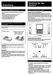
...; Use only the supplied speakers for a long time, remove the batteries. to observe the terminal polarity when making rear speaker connections. When this happens, replace both batteries. Also, to obtain the best central sound image, we recommend placing the left of the front speakers To obtain high sound quality and a proper sound image from the TV. 1 Open the cover. 2 Insert two size-AA (R6) batteries with the built-in rear speaker amplifier uses...
...; Use only the supplied speakers for a long time, remove the batteries. to observe the terminal polarity when making rear speaker connections. When this happens, replace both batteries. Also, to obtain the best central sound image, we recommend placing the left of the front speakers To obtain high sound quality and a proper sound image from the TV. 1 Open the cover. 2 Insert two size-AA (R6) batteries with the built-in rear speaker amplifier uses...
Operating Instructions
Page 8
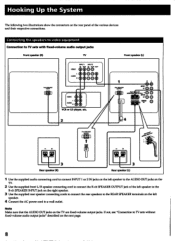
.... 8 Connecting the speakers to video equipment Connection to a wall outlet. SPEAKER OUIPU'r O O O IIIIPEONCE SE aEuNcetv 2 I WW*POO P. 1 CO P- Hooking Up the System The following two illustrations show the connectors on the rear panel of the left speaker to the R-ch SPEAKER INPUT jack on the right speaker. 3 Use the supplied rear speaker connecting cords to connect the rear speakers to the REAR SPEAKER terminals on the left speaker. 4 Connect the AC power cord to TV sets with fixed-volume audio output jacks Front speaker (R) TV VIDEO AUDIO INPUT...
.... 8 Connecting the speakers to video equipment Connection to a wall outlet. SPEAKER OUIPU'r O O O IIIIPEONCE SE aEuNcetv 2 I WW*POO P. 1 CO P- Hooking Up the System The following two illustrations show the connectors on the rear panel of the left speaker to the R-ch SPEAKER INPUT jack on the right speaker. 3 Use the supplied rear speaker connecting cords to connect the rear speakers to the REAR SPEAKER terminals on the left speaker. 4 Connect the AC power cord to TV sets with fixed-volume audio output jacks Front speaker (R) TV VIDEO AUDIO INPUT...
Operating Instructions
Page 9
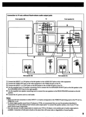
... INPUT 1 or 2 jacks corresponds to the VIDEO IN jack being used on the left speaker. 6 Connect the AC power cord to connect your VCR or LD player, even another pair of sound quality. 9 Connection of both pairs of jacks at the same time will cause noise or degradation of audio output jacks is available. Notes • Make sure that you use the procedure described in "Connection to TV sets without fixed-volume audio output jacks" to connect the speaker...
... INPUT 1 or 2 jacks corresponds to the VIDEO IN jack being used on the left speaker. 6 Connect the AC power cord to connect your VCR or LD player, even another pair of sound quality. 9 Connection of both pairs of jacks at the same time will cause noise or degradation of audio output jacks is available. Notes • Make sure that you use the procedure described in "Connection to TV sets without fixed-volume audio output jacks" to connect the speaker...
Operating Instructions
Page 10
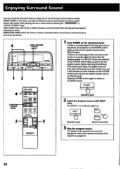
... 3 Play the program source. If there is in stereo. If there is an audio signal when you turn on the power or an audio signal is input when the speaker system is no audio signal at the time you turn on the power, the indicator on the POWER switch turns red and the speaker system returns to STANDBY mode. 0 POWER Operation panel 2 Select the program source with INPUT (1/2). HALL mode: Select this mode to obtain dynamic surround sound...
... 3 Play the program source. If there is in stereo. If there is an audio signal when you turn on the power or an audio signal is input when the speaker system is no audio signal at the time you turn on the power, the indicator on the POWER switch turns red and the speaker system returns to STANDBY mode. 0 POWER Operation panel 2 Select the program source with INPUT (1/2). HALL mode: Select this mode to obtain dynamic surround sound...
Operating Instructions
Page 11
... the surround sound mode. DOLBY PRO LOGIC ON/OFF MOOS PRO LOGIC ON/OFF MODE Operation panel Remote commander Note The DOLBY PRO LOGIC MODE button is operable only when an external center speaker is connected to light up and powerful bass sound is output. Each press of rear sound information. 11 "MUTE" appears on the display. To select either mode, press SUPER WOOFER MODE button to turn off SURROUND SURROUND Operation panel 5 Adjust the volume. "PRO LOGIC" appears on the display and the sound...
... the surround sound mode. DOLBY PRO LOGIC ON/OFF MOOS PRO LOGIC ON/OFF MODE Operation panel Remote commander Note The DOLBY PRO LOGIC MODE button is operable only when an external center speaker is connected to light up and powerful bass sound is output. Each press of rear sound information. 11 "MUTE" appears on the display. To select either mode, press SUPER WOOFER MODE button to turn off SURROUND SURROUND Operation panel 5 Adjust the volume. "PRO LOGIC" appears on the display and the sound...
Operating Instructions
Page 12
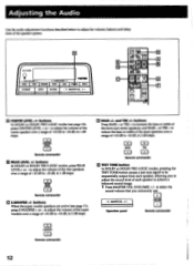
... of the speaker system. VOLUME Operation panel 0 Remote commander =I TRE CD Remote commander E TEST TONE button In DOLBY or DOLBY PRO LOGIC modes, pressing the TEST TONE button causes a test tone signal to be sequentially output from each speaker, allowing you commonly use. - 0 MASTER VOL 0 4. buttons In DOLBY or DOLBY PRO LOGIC modes (see page 11), press S.WOOFER + or - to adjust the volume of the center speaker over...
... of the speaker system. VOLUME Operation panel 0 Remote commander =I TRE CD Remote commander E TEST TONE button In DOLBY or DOLBY PRO LOGIC modes, pressing the TEST TONE button causes a test tone signal to be sequentially output from each speaker, allowing you commonly use. - 0 MASTER VOL 0 4. buttons In DOLBY or DOLBY PRO LOGIC modes (see page 11), press S.WOOFER + or - to adjust the volume of the center speaker over...
Operating Instructions
Page 13
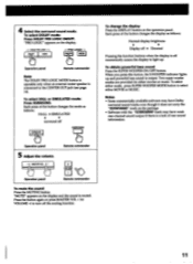
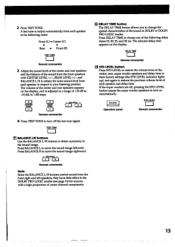
... is output automatically from each speaker in 1 dB steps. DELAY TIME ED Remote commander El STD LEVEL button Press STD LEVEL to restore the volume level of each speaker in DOLBY or DOLBY PRO LOGIC modes. A test tone is adjusted in a range of +10 dB to restore the previous volume level of the center, rear, super woofer speakers and delay time to their factory settings (the STD LEVEL indicator lights...
... is output automatically from each speaker in 1 dB steps. DELAY TIME ED Remote commander El STD LEVEL button Press STD LEVEL to restore the volume level of each speaker in DOLBY or DOLBY PRO LOGIC modes. A test tone is adjusted in a range of +10 dB to restore the previous volume level of the center, rear, super woofer speakers and delay time to their factory settings (the STD LEVEL indicator lights...
Operating Instructions
Page 14
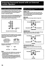
... speakers output the bass sound of the rear channel. Enjoying Surround Sound with a built-in amplifier or through SA-VAT's "enhanced theater mode speaker system". Front speaker (L) Front speaker (R) Rear speaker (L) CiD te.,+Rear speaker (R) PHANTOM 3CH (channel) LOGIC mode Select this mode when using only the front and center speakers. Center speaker Front speakerL) d ij Front speaker (R) CID 301 LOGIC 14 Be sure to set the volume of the front left front speaker Press DOLBY PRO LOGIC ON/OFF to activate a connected external center speaker...
... speakers output the bass sound of the rear channel. Enjoying Surround Sound with a built-in amplifier or through SA-VAT's "enhanced theater mode speaker system". Front speaker (L) Front speaker (R) Rear speaker (L) CiD te.,+Rear speaker (R) PHANTOM 3CH (channel) LOGIC mode Select this mode when using only the front and center speakers. Center speaker Front speakerL) d ij Front speaker (R) CID 301 LOGIC 14 Be sure to set the volume of the front left front speaker Press DOLBY PRO LOGIC ON/OFF to activate a connected external center speaker...
Operating Instructions
Page 15
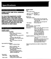
... 12 oz) Supplied accessories Front L/R speaker connecting cord, 3.5 m (1) Rear speaker connecting cord, 10 m (2) Audio connecting cord, 1.5 m (1) Remote commander RM-VAI (1) Sony batteries SUM-3 (NS) (2) Design and specifications are subject to rated output. rated 18 watts per channel minimum RMS power, with supplied front L/R speaker connecting cord Tone control Front/center Super woofer Bass: ±10 dB at 100 Hz Treble: ±10 dB at 10 kHz +10 dB at 1 kHz, 10% THD) Input sensitivity/impedance INPUT 1/2: 450 mV, 50 Id/ Output INPUT 1/2: 450 mV...
... 12 oz) Supplied accessories Front L/R speaker connecting cord, 3.5 m (1) Rear speaker connecting cord, 10 m (2) Audio connecting cord, 1.5 m (1) Remote commander RM-VAI (1) Sony batteries SUM-3 (NS) (2) Design and specifications are subject to rated output. rated 18 watts per channel minimum RMS power, with supplied front L/R speaker connecting cord Tone control Front/center Super woofer Bass: ±10 dB at 100 Hz Treble: ±10 dB at 10 kHz +10 dB at 1 kHz, 10% THD) Input sensitivity/impedance INPUT 1/2: 450 mV, 50 Id/ Output INPUT 1/2: 450 mV...
Operating Instructions
Page 16
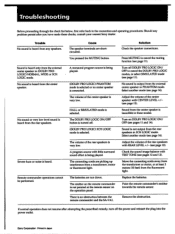
... speaker connections. The connecting cords are picking up interference from any problem persist after attempting the prescribed remedy, turn off the power and reinsert the plug into the power outlet. Point the remote commander's emitter towards the remote sensor. Turn on the operation panel. Trouble No sound is not output from the external center speaker in Japan Severe hum or noise is selected. HALL or SIMULATED mode is heard. Adjust the volume...
... speaker connections. The connecting cords are picking up interference from any problem persist after attempting the prescribed remedy, turn off the power and reinsert the plug into the power outlet. Point the remote commander's emitter towards the remote sensor. Turn on the operation panel. Trouble No sound is not output from the external center speaker in Japan Severe hum or noise is selected. HALL or SIMULATED mode is heard. Adjust the volume...


