
Service Manual
Page 2
...-540A. SAFETY-RELATED COMPONENT WARNING!! A battery-operated AC milliammeter. Power Section 9 2-6. Printed Wiring Board - REPLACE THESE COMPONENTS WITH SONY PARTS WHOSE PART NUMBERS APPEAR AS SHOWN IN THIS MANUAL OR IN SUPPLEMENTS PUBLISHED BY SONY. 2 Nearly all battery operated digital multimeters that is suitable. SAFETY CHECK-OUT After correcting the original service problem, perform...
...-540A. SAFETY-RELATED COMPONENT WARNING!! A battery-operated AC milliammeter. Power Section 9 2-6. Printed Wiring Board - REPLACE THESE COMPONENTS WITH SONY PARTS WHOSE PART NUMBERS APPEAR AS SHOWN IN THIS MANUAL OR IN SUPPLEMENTS PUBLISHED BY SONY. 2 Nearly all battery operated digital multimeters that is suitable. SAFETY CHECK-OUT After correcting the original service problem, perform...

Service Manual
Page 5
...3 Set the cueing lever to a 50 Hz power source, the uppermost row of another part of 10% in the up position and return the tonearm to ON. When the turntable is turned on one turntable with the speed of both selections. If you have an extra headshell, keep it to...cover from the side which enables seeing. Attach the protective cover onto the cartridge to prevent damage to play an another selection playing on the stereo component system or amplifier. MAIN SECTION - 1 IC7 0 Operations To play 10% faster or slower than the normal playing speed. Pressing and holding down ...
...3 Set the cueing lever to a 50 Hz power source, the uppermost row of another part of 10% in the up position and return the tonearm to ON. When the turntable is turned on one turntable with the speed of both selections. If you have an extra headshell, keep it to...cover from the side which enables seeing. Attach the protective cover onto the cartridge to prevent damage to play an another selection playing on the stereo component system or amplifier. MAIN SECTION - 1 IC7 0 Operations To play 10% faster or slower than the normal playing speed. Pressing and holding down ...

Service Manual
Page 8
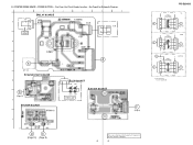
... D-5 Q12 D-7 Q61 D-3 Q62 D-3 1 E E 1 4 E E E 21 OGI 1 E E E 10 1 14 14 8 1 7 K A K 14 8 1 7 E 14 8 1 7 14 8 14 8 7 1 7 1 7 G B (Page 9) (Page 10) A (Page 10) F (Page 9) E (Page 9) 8 8 There are a few cases that the part isn't mounted in model is printed on diagram. No. MAIN SECTION - • See Page 5 for Circut Boards Location. • See Page 6 for Schematic Diagram. 1 2 3 4 5 6 7 8 9 MAIN...
... D-5 Q12 D-7 Q61 D-3 Q62 D-3 1 E E 1 4 E E E 21 OGI 1 E E E 10 1 14 14 8 1 7 K A K 14 8 1 7 E 14 8 1 7 14 8 14 8 7 1 7 1 7 G B (Page 9) (Page 10) A (Page 10) F (Page 9) E (Page 9) 8 8 There are a few cases that the part isn't mounted in model is printed on diagram. No. MAIN SECTION - • See Page 5 for Circut Boards Location. • See Page 6 for Schematic Diagram. 1 2 3 4 5 6 7 8 9 MAIN...
Service Manual
Page 9
... D E (Page 10) (Page 8) 4 LED BOARD LD06 LD05 LD03 LD04 STROBO LAMP LED SW BOARD F (Page 8) There are a few cases that the part isn't mounted in model is printed on diagram. 9 9 PS-DJ9000 US POWER TRANSFORMER 4 C (Page 10) POWER TRANSFORMER 4 * 5 * POWER TRANSFORMER 4 E, MX C (Page 10) AEP, UK C (Page 10) * NOT REPLACEBLE: BUILT IN TRANSFORMER...
... D E (Page 10) (Page 8) 4 LED BOARD LD06 LD05 LD03 LD04 STROBO LAMP LED SW BOARD F (Page 8) There are a few cases that the part isn't mounted in model is printed on diagram. 9 9 PS-DJ9000 US POWER TRANSFORMER 4 C (Page 10) POWER TRANSFORMER 4 * 5 * POWER TRANSFORMER 4 E, MX C (Page 10) AEP, UK C (Page 10) * NOT REPLACEBLE: BUILT IN TRANSFORMER...
Service Manual
Page 11
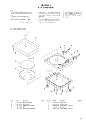
... the original one. • Color Indication of the electrical parts list. No. 6 7 8 9 10 Part No. Some delay should be anticipated when ordering these items. • The mechanical parts with part number specified. 3-1. No. 1 2 3 4 5 Part No. Replace only with no reference number in the exploded ...views are not supplied. • Accessories and packing materials are given in the last of Appearance Parts Example: KNOB, BALANCE (WHITE) . . . (RED) ↑ ↑ Parts Color Cabinet's Color SECTION 3 EXPLODED VIEW • Items marked "*" are not stocked since they are...
... the original one. • Color Indication of the electrical parts list. No. 6 7 8 9 10 Part No. Some delay should be anticipated when ordering these items. • The mechanical parts with part number specified. 3-1. No. 1 2 3 4 5 Part No. Replace only with no reference number in the exploded ...views are not supplied. • Accessories and packing materials are given in the last of Appearance Parts Example: KNOB, BALANCE (WHITE) . . . (RED) ↑ ↑ Parts Color Cabinet's Color SECTION 3 EXPLODED VIEW • Items marked "*" are not stocked since they are...

Service Manual
Page 12
No. 51 53 54 54 56 57 58 59 60 61 62 63 63 Part No. No. 64 65 66 66 67 68 69 70 72 73 74 T1 T1 T1 Part No. Ver 1.1 2001.06 3-2. Description A-4412-592-A MOTOR BOARD, COMPLETE 4-231-231-01 TERGET (LIGHT) ASSY 4-231-232-01 BASE ASSY...
No. 51 53 54 54 56 57 58 59 60 61 62 63 63 Part No. No. 64 65 66 66 67 68 69 70 72 73 74 T1 T1 T1 Part No. Ver 1.1 2001.06 3-2. Description A-4412-592-A MOTOR BOARD, COMPLETE 4-231-231-01 TERGET (LIGHT) ASSY 4-231-232-01 BASE ASSY...

Service Manual
Page 13
... • RESISTORS All resistors are in the diagrams or the components used on the set. • -XX and -X mean standardized parts, so they are seldom required for routine service. METAL OXIDE: Metal oxide-film resistor. Replace only with mark 0 are not stocked ...marked "*" are critical for example: uA. . : µA. . uPC. . : µPC. . SECTION 4 ELECTRICAL PARTS LIST LED LED SW MAIN NOTE: • Due to standardization, replacements in the parts list may be anticipated when ordering these items. • SEMICONDUCTORS In each case, u: µ, for safety. Some delay should...
... • RESISTORS All resistors are in the diagrams or the components used on the set. • -XX and -X mean standardized parts, so they are seldom required for routine service. METAL OXIDE: Metal oxide-film resistor. Replace only with mark 0 are not stocked ...marked "*" are critical for example: uA. . : µA. . uPC. . : µPC. . SECTION 4 ELECTRICAL PARTS LIST LED LED SW MAIN NOTE: • Due to standardization, replacements in the parts list may be anticipated when ordering these items. • SEMICONDUCTORS In each case, u: µ, for safety. Some delay should...

Service Manual
Page 15
... (US,MX) 1-435-744-11 TRANSFORMER, POWER (AEP,UK) 1-435-745-11 TRANSFORMER, POWER (E) Description Remark The components identified by mark 0 or dotted line with part number specified. 15 Description PAUSE/START BOARD Remark Ref. Replace only with mark 0 are critical for safety...
... (US,MX) 1-435-744-11 TRANSFORMER, POWER (AEP,UK) 1-435-745-11 TRANSFORMER, POWER (E) Description Remark The components identified by mark 0 or dotted line with part number specified. 15 Description PAUSE/START BOARD Remark Ref. Replace only with mark 0 are critical for safety...
