
Service Manual
Page 2
... measured by means of three methods. 1. Printed Wiring Board - A battery-operated AC milliammeter. Power Section 9 2-6. REPLACE THESE COMPONENTS WITH SONY PARTS WHOSE PART NUMBERS APPEAR AS SHOWN IN THIS MANUAL OR IN SUPPLEMENTS PUBLISHED BY SONY. 2 Main Section 6 2-3. A) TABLE OF CONTENTS 1. Follow the manufacturers' instructions to check AC leakage. Printed Wiring Board - Circuit boards...
... measured by means of three methods. 1. Printed Wiring Board - A battery-operated AC milliammeter. Power Section 9 2-6. REPLACE THESE COMPONENTS WITH SONY PARTS WHOSE PART NUMBERS APPEAR AS SHOWN IN THIS MANUAL OR IN SUPPLEMENTS PUBLISHED BY SONY. 2 Main Section 6 2-3. A) TABLE OF CONTENTS 1. Follow the manufacturers' instructions to check AC leakage. Printed Wiring Board - Circuit boards...

Service Manual
Page 5
...otherwise specified. • C : panel designation. button causes the selection to the previous pitch setting (the QUARTZ indicator will turn on the stereo component system or amplifier. Note on • Voltages are dc with the speed of the selection on the record. 7 Set the cueing lever to ... position to raise the stylus. 2 Move the tonearm to the desired position. 3 Set the cueing lever to normal production tolerances. Note Place only one turntable with part number specified. • U : B+ Line. • V : B- pF: µµF 50 WV or less are not stationary when the PITCH...
...otherwise specified. • C : panel designation. button causes the selection to the previous pitch setting (the QUARTZ indicator will turn on the stereo component system or amplifier. Note on • Voltages are dc with the speed of the selection on the record. 7 Set the cueing lever to ... position to raise the stylus. 2 Move the tonearm to the desired position. 3 Set the cueing lever to normal production tolerances. Note Place only one turntable with part number specified. • U : B+ Line. • V : B- pF: µµF 50 WV or less are not stationary when the PITCH...

Service Manual
Page 8
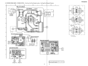
... D-5 Q12 D-7 Q61 D-3 Q62 D-3 1 E E 1 4 E E E 21 OGI 1 E E E 10 1 14 14 8 1 7 K A K 14 8 1 7 E 14 8 1 7 14 8 14 8 7 1 7 1 7 G B (Page 9) (Page 10) A (Page 10) F (Page 9) E (Page 9) 8 8 There are a few cases that the part isn't mounted in model is printed on diagram. No. PRINTED WIRING BOARD - PS-DJ9000 2-4.
... D-5 Q12 D-7 Q61 D-3 Q62 D-3 1 E E 1 4 E E E 21 OGI 1 E E E 10 1 14 14 8 1 7 K A K 14 8 1 7 E 14 8 1 7 14 8 14 8 7 1 7 1 7 G B (Page 9) (Page 10) A (Page 10) F (Page 9) E (Page 9) 8 8 There are a few cases that the part isn't mounted in model is printed on diagram. No. PRINTED WIRING BOARD - PS-DJ9000 2-4.
Service Manual
Page 9
... D E (Page 10) (Page 8) 4 LED BOARD LD06 LD05 LD03 LD04 STROBO LAMP LED SW BOARD F (Page 8) There are a few cases that the part isn't mounted in model is printed on diagram. 9 9 PS-DJ9000 US POWER TRANSFORMER 4 C (Page 10) POWER TRANSFORMER 4 * 5 * POWER TRANSFORMER 4 E, MX C (Page 10) AEP, UK C (Page 10) * NOT REPLACEBLE: BUILT IN TRANSFORMER...
... D E (Page 10) (Page 8) 4 LED BOARD LD06 LD05 LD03 LD04 STROBO LAMP LED SW BOARD F (Page 8) There are a few cases that the part isn't mounted in model is printed on diagram. 9 9 PS-DJ9000 US POWER TRANSFORMER 4 C (Page 10) POWER TRANSFORMER 4 * 5 * POWER TRANSFORMER 4 E, MX C (Page 10) AEP, UK C (Page 10) * NOT REPLACEBLE: BUILT IN TRANSFORMER...
Service Manual
Page 11
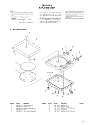
...-79 SCREW +P3x20 TYPE2 SLIT Remark 11 Replace only with no reference number in the last of Appearance Parts Example: KNOB, BALANCE (WHITE) . . . (RED) ↑ ↑ Parts Color Cabinet's Color SECTION 3 EXPLODED VIEW • Items marked "*" are not stocked since they are ...critical for routine service. Some delay should be anticipated when ordering these items. • The mechanical parts with part number specified. 3-1. NOTE: • -XX and -X mean standardized parts, so they may have some difference from the original one. • Color Indication of the electrical...
...-79 SCREW +P3x20 TYPE2 SLIT Remark 11 Replace only with no reference number in the last of Appearance Parts Example: KNOB, BALANCE (WHITE) . . . (RED) ↑ ↑ Parts Color Cabinet's Color SECTION 3 EXPLODED VIEW • Items marked "*" are not stocked since they are ...critical for routine service. Some delay should be anticipated when ordering these items. • The mechanical parts with part number specified. 3-1. NOTE: • -XX and -X mean standardized parts, so they may have some difference from the original one. • Color Indication of the electrical...

Service Manual
Page 12
No. 64 65 66 66 67 68 69 70 72 73 74 T1 T1 T1 Part No. Ver 1.1 2001.06 3-2. Description A-4412-592-A MOTOR BOARD, COMPLETE 4-231-231-01 TERGET (LIGHT) ASSY 4-231-232-01 BASE ASSY, KNOB (AEP,UK) 4-232-...-11 TRANSFORMER, POWER (AEP,UK) 1-435-745-11 TRANSFORMER, POWER (E) 12 No. 51 53 54 54 56 57 58 59 60 61 62 63 63 Part No.
No. 64 65 66 66 67 68 69 70 72 73 74 T1 T1 T1 Part No. Ver 1.1 2001.06 3-2. Description A-4412-592-A MOTOR BOARD, COMPLETE 4-231-231-01 TERGET (LIGHT) ASSY 4-231-232-01 BASE ASSY, KNOB (AEP,UK) 4-232-...-11 TRANSFORMER, POWER (AEP,UK) 1-435-745-11 TRANSFORMER, POWER (E) 12 No. 51 53 54 54 56 57 58 59 60 61 62 63 63 Part No.

Service Manual
Page 13
...Ref. F: nonflammable • Items marked "*" are in ohms. METAL: Metal-film resistor. uPA. . : µPA. . When indicating parts by mark 0 or dotted line with part number specified. Part No. uPB. . : µPB. . Description < DIODE > 8-719-107-94 DIODE 1SS132T-73 8-719-107-94 DIODE 1SS132T-73 8-...for routine service. Replace only with mark 0 are seldom required for safety. D4 D5 D9 D10 D19 D20 Part No. Some delay should be different from the parts specified in either one . • RESISTORS All resistors are not stocked since they may be anticipated when ordering...
...Ref. F: nonflammable • Items marked "*" are in ohms. METAL: Metal-film resistor. uPA. . : µPA. . When indicating parts by mark 0 or dotted line with part number specified. Part No. uPB. . : µPB. . Description < DIODE > 8-719-107-94 DIODE 1SS132T-73 8-719-107-94 DIODE 1SS132T-73 8-...for routine service. Replace only with mark 0 are seldom required for safety. D4 D5 D9 D10 D19 D20 Part No. Some delay should be different from the parts specified in either one . • RESISTORS All resistors are not stocked since they may be anticipated when ordering...

Service Manual
Page 15
...,MX) 1-435-744-11 TRANSFORMER, POWER (AEP,UK) 1-435-745-11 TRANSFORMER, POWER (E) Description Remark The components identified by mark 0 or dotted line with part number specified. 15 Part No. Part No. PAUSE/START POWER RELAY TONE ARM Ref. Description PAUSE/START BOARD Remark Ref. Replace only with mark 0 are critical for safety.
...,MX) 1-435-744-11 TRANSFORMER, POWER (AEP,UK) 1-435-745-11 TRANSFORMER, POWER (E) Description Remark The components identified by mark 0 or dotted line with part number specified. 15 Part No. Part No. PAUSE/START POWER RELAY TONE ARM Ref. Description PAUSE/START BOARD Remark Ref. Replace only with mark 0 are critical for safety.
