
Operating Instructions
Page 4
...Multipoint Setup Menu 57 Machine Information Menu ........59 Status Menu 60 Encryption via an ISDN 23 Preparing the System 24 Inserting Batteries into the Remote Commander 24 Turning On/Off the TV Monitor Together With the Communication Terminal 25 Turning the System On/Off 26 Turning On 26 Standby... Mode Function 27 Setting the Video Communication System to Standby Mode 28 Adjusting the Volume on the TV Monitor 29 Turning Off 29 Displaying the Versions and Options 30 ...
...Multipoint Setup Menu 57 Machine Information Menu ........59 Status Menu 60 Encryption via an ISDN 23 Preparing the System 24 Inserting Batteries into the Remote Commander 24 Turning On/Off the TV Monitor Together With the Communication Terminal 25 Turning the System On/Off 26 Turning On 26 Standby... Mode Function 27 Setting the Video Communication System to Standby Mode 28 Adjusting the Volume on the TV Monitor 29 Turning Off 29 Displaying the Versions and Options 30 ...

Operating Instructions
Page 5
... - Muting Function ...........85 Synchronizing Audio and Video - Copying the Setting of the Phone Book Menu 66 Deleting the Registered Remote Party 66 Creating a Private Phone Book ..66 Chapter 3: Daily Videoconference Starting a Conference by Calling a Remote Party 69 Turning on the Power 69 Using... the Launcher Menu ..........70 Selecting the Video/Audio Quality Mode 73 Calling a Remote Party 74 Receiving a Call from a Remote Party 82 Answering a Call from a Remote Party 110 Saving Still Images to the Remote Party 97 Switching the Picture Displayed on Answer Function...
... - Muting Function ...........85 Synchronizing Audio and Video - Copying the Setting of the Phone Book Menu 66 Deleting the Registered Remote Party 66 Creating a Private Phone Book ..66 Chapter 3: Daily Videoconference Starting a Conference by Calling a Remote Party 69 Turning on the Power 69 Using... the Launcher Menu ..........70 Selecting the Video/Audio Quality Mode 73 Calling a Remote Party 74 Receiving a Call from a Remote Party 82 Answering a Call from a Remote Party 110 Saving Still Images to the Remote Party 97 Switching the Picture Displayed on Answer Function...

Operating Instructions
Page 6
...Example Using the Data Solution Box 133 To connect the CTE-600 Communication Transducer 135 Using Audio/Video Signal from the Connected Equipment for a Conference 136 Setting Before Conferencing .... 136 6 Operating the System During a Conference 136 Displaying the Picture on a Projector or...Microphones ......... 118 Using the Communication Transducer (CTE 120 Recording Audio During a Conference 122 Sending Audio/Video from the External Equipment to a Remote Party ........ 123 Outputting Video Signals to 10 Points) ..155 Using the ISDN Connection .....156 Using the LAN and ISDN ...
...Example Using the Data Solution Box 133 To connect the CTE-600 Communication Transducer 135 Using Audio/Video Signal from the Connected Equipment for a Conference 136 Setting Before Conferencing .... 136 6 Operating the System During a Conference 136 Displaying the Picture on a Projector or...Microphones ......... 118 Using the Communication Transducer (CTE 120 Recording Audio During a Conference 122 Sending Audio/Video from the External Equipment to a Remote Party ........ 123 Outputting Video Signals to 10 Points) ..155 Using the ISDN Connection .....156 Using the LAN and ISDN ...

Operating Instructions
Page 7
... 202 Troubleshooting 212 Specifications 216 PCS-P1/P1P Communication Terminal 216 PCS-C1/C1P Camera Unit ....... 217 PCS-R1 Remote Commander .. 217 PCS-AC195 AC Adaptor ......... 217 PCS-A1 Microphone (Optional 217 PCS-B384 ISDN Unit (Optional 218 PCS-B768 ISDN Unit (Optional 218 PCS-A300 Microphone (Optional 218 PCS-DSB1 Data Solution Box (Optional 218 PCS-320M1 H.320 MCU Software...
... 202 Troubleshooting 212 Specifications 216 PCS-P1/P1P Communication Terminal 216 PCS-C1/C1P Camera Unit ....... 217 PCS-R1 Remote Commander .. 217 PCS-AC195 AC Adaptor ......... 217 PCS-A1 Microphone (Optional 217 PCS-B384 ISDN Unit (Optional 218 PCS-B768 ISDN Unit (Optional 218 PCS-A300 Microphone (Optional 218 PCS-DSB1 Data Solution Box (Optional 218 PCS-320M1 H.320 MCU Software...

Operating Instructions
Page 10
... PCS320M1 H.320 MCU software are separately displayed. Supports ITU-T international videoconferencing standard The Video Communication System complies with ITU-T Recommendations defined by using the optional PCS-B768 ISDN Unit. 10 Features Wide range of still images recorded with remote parties overseas. Easy setup and operation The Help menu appears on the projector. Supports...
... PCS320M1 H.320 MCU software are separately displayed. Supports ITU-T international videoconferencing standard The Video Communication System complies with ITU-T Recommendations defined by using the optional PCS-B768 ISDN Unit. 10 Features Wide range of still images recorded with remote parties overseas. Easy setup and operation The Help menu appears on the projector. Supports...

Operating Instructions
Page 12
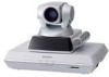
PCS-R1 Remote Commander Used to the Communication Terminal. 12 System Components PCS-AC195 AC adaptor Supplies power to operate the Communication Terminal and Camera Unit. Basic System Components The PCS-1/1P Video Communication System is composed of basic system components for a basic videoconference, and optional equipment for an enhanced videoconference. PCS...components: Unit Description PCS-P1/P1P Communication Contains the video codec, audio codec, echo Terminal canceler, network interfaces and system controller. System Components The PCS-1/1P Video Communication System is...
PCS-R1 Remote Commander Used to the Communication Terminal. 12 System Components PCS-AC195 AC adaptor Supplies power to operate the Communication Terminal and Camera Unit. Basic System Components The PCS-1/1P Video Communication System is composed of basic system components for a basic videoconference, and optional equipment for an enhanced videoconference. PCS...components: Unit Description PCS-P1/P1P Communication Contains the video codec, audio codec, echo Terminal canceler, network interfaces and system controller. System Components The PCS-1/1P Video Communication System is...

Operating Instructions
Page 14
...this system. Allows conduct of pictures to connect devices in all directions. PCS-1/1P Video Communication System Cable Part No. The uni-directional microphones pick up clear ...PCS-320M1 H.320 MCU Software PCSA-SP1 SIP Software Allows use for a multipoint videoconference over LAN connection. Camera cable (0.25 m (0.8 feet)) 1-827-376-11 S-video connecting cable (1.5 m (4.9 feet)) 1-776-078-42 Audio connecting cable (1 m (3.3 feet)) 1-765-258-31 Number 1 1 1 Camera cable S-video connecting cable Audio connecting cable 14 System Components Allows use for remote...
...this system. Allows conduct of pictures to connect devices in all directions. PCS-1/1P Video Communication System Cable Part No. The uni-directional microphones pick up clear ...PCS-320M1 H.320 MCU Software PCSA-SP1 SIP Software Allows use for a multipoint videoconference over LAN connection. Camera cable (0.25 m (0.8 feet)) 1-827-376-11 S-video connecting cable (1.5 m (4.9 feet)) 1-776-078-42 Audio connecting cable (1 m (3.3 feet)) 1-765-258-31 Number 1 1 1 Camera cable S-video connecting cable Audio connecting cable 14 System Components Allows use for remote...

Operating Instructions
Page 15
This section describes seven typical examples. System configuration 1 PCS-P1/P1P Communication Terminal 2 PCS-C1/C1P Camera Unit 3 PCS-R1 Remote Commander 4 TV monitor (not supplied) ON LINE POWER LAN ALERT ON LINE POWER LAN ALERT System Configuration 15 System Configuration via a LAN ... hold a point-to-point videoconference over LAN. • To show still images stored in a "Memory Stick". Chapter 1: Installation and Preparation System Configuration The PCS-1/1P Video Communication System has various system configuration capabilities using the basic components and optional equipment.
This section describes seven typical examples. System configuration 1 PCS-P1/P1P Communication Terminal 2 PCS-C1/C1P Camera Unit 3 PCS-R1 Remote Commander 4 TV monitor (not supplied) ON LINE POWER LAN ALERT ON LINE POWER LAN ALERT System Configuration 15 System Configuration via a LAN ... hold a point-to-point videoconference over LAN. • To show still images stored in a "Memory Stick". Chapter 1: Installation and Preparation System Configuration The PCS-1/1P Video Communication System has various system configuration capabilities using the basic components and optional equipment.

Operating Instructions
Page 16
... images stored in a "Memory Stick". • To hold a videoconference with this system. System configuration 1 PCS-P1/P1P Communication Terminal 2 PCS-C1/C1P Camera Unit 3 PCS-R1 Remote Commander 4 TV monitor (not supplied) ON LINE POWER LAN ALERT * 5 PCS-B384 or PCS-B768 ISDN Unit (not supplied) * ON LINE POWER LAN ALERT * The illustration shows an example...
... images stored in a "Memory Stick". • To hold a videoconference with this system. System configuration 1 PCS-P1/P1P Communication Terminal 2 PCS-C1/C1P Camera Unit 3 PCS-R1 Remote Commander 4 TV monitor (not supplied) ON LINE POWER LAN ALERT * 5 PCS-B384 or PCS-B768 ISDN Unit (not supplied) * ON LINE POWER LAN ALERT * The illustration shows an example...

Operating Instructions
Page 17
... still images on the second TV monitor or projector. • To pick up a large number of participants' voices using up to install the optional PCS-323M1 H.323 MCU software. System configuration ON LINE POWER LAN ALERT ON LINE POWER LAN ALERT ON LINE POWER LAN ALERT ON LINE POWER LAN...ON LINE POWER LAN ALERT ON LINE POWER LAN ALERT ON LINE POWER LAN ALERT ON LINE POWER LAN ALERT ON LINE POWER LAN ALERT 1 PCS-P1/P1P Communication Terminal 2 PCS-C1/C1P Camera Unit 3 PCS-R1 Remote Commander 4 TV monitor (not supplied) 5 PCS-323M1 H.323 MCU software (not supplied) System Configuration 17
... still images on the second TV monitor or projector. • To pick up a large number of participants' voices using up to install the optional PCS-323M1 H.323 MCU software. System configuration ON LINE POWER LAN ALERT ON LINE POWER LAN ALERT ON LINE POWER LAN ALERT ON LINE POWER LAN...ON LINE POWER LAN ALERT ON LINE POWER LAN ALERT ON LINE POWER LAN ALERT ON LINE POWER LAN ALERT ON LINE POWER LAN ALERT 1 PCS-P1/P1P Communication Terminal 2 PCS-C1/C1P Camera Unit 3 PCS-R1 Remote Commander 4 TV monitor (not supplied) 5 PCS-323M1 H.323 MCU software (not supplied) System Configuration 17

Operating Instructions
Page 18
...• To show the still images on the second TV monitor or projector. • To pick up a large number of participants' voices using the PCS-B768 ISDN Unit. 18 System Configuration System configuration ON LINE POWER LAN ALERT ON LINE POWER LAN ALERT ON LINE POWER LAN ALERT 1 2 3 4... ALERT ON LINE POWER LAN ALERT ON LINE POWER LAN ALERT 1 PCS-P1/P1P Communication Terminal 2 PCS-C1/C1P Camera Unit 3 PCS-R1 Remote Commander 4 TV monitor (not supplied) 5 PCS-320M1 H.320 MCU software (not supplied) 6 PCS-B384 or PCS-B768 ISDN Unit (not supplied) The illustration shows an example using...
...• To show the still images on the second TV monitor or projector. • To pick up a large number of participants' voices using the PCS-B768 ISDN Unit. 18 System Configuration System configuration ON LINE POWER LAN ALERT ON LINE POWER LAN ALERT ON LINE POWER LAN ALERT 1 2 3 4... ALERT ON LINE POWER LAN ALERT ON LINE POWER LAN ALERT 1 PCS-P1/P1P Communication Terminal 2 PCS-C1/C1P Camera Unit 3 PCS-R1 Remote Commander 4 TV monitor (not supplied) 5 PCS-320M1 H.320 MCU software (not supplied) 6 PCS-B384 or PCS-B768 ISDN Unit (not supplied) The illustration shows an example using...

Operating Instructions
Page 19
...POWER LAN ALERT ON LINE POWER LAN ALERT 1 PCS-P1/P1P Communication Terminal 2 PCS-C1/C1P Camera Unit 3 PCS-R1 Remote Commander 4 TV monitor (not supplied) 5 PCS-323M1 H.323 MCU software (not supplied) 6 PCS-320M1 H.320 MCU software (not supplied) 7 PCS-B384 or PCS-B768 ISDN Unit (not supplied) * Be ...System Configuration 19 Chapter 1: Installation and Preparation System Configuration via a LAN and ISDN for Multipoint Conference Installing the optional PCS-323M1 H.323 MCU software (for LAN) and PCS320M1 H.320 MCU software (for ISDN) enables conduct of participants' voices using the...
...POWER LAN ALERT ON LINE POWER LAN ALERT 1 PCS-P1/P1P Communication Terminal 2 PCS-C1/C1P Camera Unit 3 PCS-R1 Remote Commander 4 TV monitor (not supplied) 5 PCS-323M1 H.323 MCU software (not supplied) 6 PCS-320M1 H.320 MCU software (not supplied) 7 PCS-B384 or PCS-B768 ISDN Unit (not supplied) * Be ...System Configuration 19 Chapter 1: Installation and Preparation System Configuration via a LAN and ISDN for Multipoint Conference Installing the optional PCS-323M1 H.323 MCU software (for LAN) and PCS320M1 H.320 MCU software (for ISDN) enables conduct of participants' voices using the...

Operating Instructions
Page 20
... LAN ALERT ON LINE POWER LAN ALERT ON LINE POWER LAN ALERT 1 PCS-P1/P1P Communication Terminal 2 PCS-C1/C1P Camera Unit 3 PCS-R1 Remote Commander 4 TV monitor (not supplied) 5 PCS-323M1 H.323 MCU software (not supplied) 6 PCS-DSB1 Data Solution Box (not supplied) 7 PCS-A1 Microphone (not supplied) 20 System Configuration This allows you: • To...
... LAN ALERT ON LINE POWER LAN ALERT ON LINE POWER LAN ALERT 1 PCS-P1/P1P Communication Terminal 2 PCS-C1/C1P Camera Unit 3 PCS-R1 Remote Commander 4 TV monitor (not supplied) 5 PCS-323M1 H.323 MCU software (not supplied) 6 PCS-DSB1 Data Solution Box (not supplied) 7 PCS-A1 Microphone (not supplied) 20 System Configuration This allows you: • To...

Operating Instructions
Page 21
... ON LINE POWER LAN ALERT 1 PCS-P1/P1P Communication Terminal 2 PCS-C1/C1P Camera Unit 3 PCS-R1 Remote Commander 4 TV monitor (not supplied) 5 PCS-320M1 H.320 MCU software (not supplied) 6 PCS-B384 or PCS-B768 ISDN Unit (not supplied) 7 PCS-DSB1 Data Solution Box (not supplied) 8 PCS-A1 Microphone (not supplied) The ... 1: Installation and Preparation System Configuration via an ISDN for Multipoint Data Conference You need to connect the optional PCS-384 or PCS-B768 ISDN Unit and the PCS-DSB1 Data Solution Box especially designed for use the data from a computer or still images on the second ...
... ON LINE POWER LAN ALERT 1 PCS-P1/P1P Communication Terminal 2 PCS-C1/C1P Camera Unit 3 PCS-R1 Remote Commander 4 TV monitor (not supplied) 5 PCS-320M1 H.320 MCU software (not supplied) 6 PCS-B384 or PCS-B768 ISDN Unit (not supplied) 7 PCS-DSB1 Data Solution Box (not supplied) 8 PCS-A1 Microphone (not supplied) The ... 1: Installation and Preparation System Configuration via an ISDN for Multipoint Data Conference You need to connect the optional PCS-384 or PCS-B768 ISDN Unit and the PCS-DSB1 Data Solution Box especially designed for use the data from a computer or still images on the second ...

Operating Instructions
Page 24
... side first may damage the insulated film covering the batteries and cause a short circuit. 3 Replace the cover. Note Be sure to use the Remote Commander for a long period of time, remove the batteries. • If battery leakage occurs, clean the battery compartment and replace all the batteries... in the correct direction. • Do not mix old and new batteries, or different types of the operations with the Video Communication System can be controlled with the supplied Remote Commander. 1 Remove the battery compartment cover. 2 Insert two size AA (R6) batteries (supplied) with new ones.
... side first may damage the insulated film covering the batteries and cause a short circuit. 3 Replace the cover. Note Be sure to use the Remote Commander for a long period of time, remove the batteries. • If battery leakage occurs, clean the battery compartment and replace all the batteries... in the correct direction. • Do not mix old and new batteries, or different types of the operations with the Video Communication System can be controlled with the supplied Remote Commander. 1 Remove the battery compartment cover. 2 Insert two size AA (R6) batteries (supplied) with new ones.
Operating Instructions
Page 25
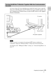
...For details on the "IR Repeater Mode" setting, see "General Setup Menu" on the Remote Commander, change the "IR Repeater Mode" setting in the General Setup menu. TV monitor CAMERA...TX 10BASE-T DSB DC 19.5V to standby together with the Communication Terminal when you use a Sony TV, insert the IR repeater under the remote sensor of the TV. Preparing the System 25 Once you set the IR repeater, the TV... will turn on or go to IR OUT Remote sensor IR repeater (supplied) Note If the TV monitor is not turned on by pressing the @/1 button on...
...For details on the "IR Repeater Mode" setting, see "General Setup Menu" on the Remote Commander, change the "IR Repeater Mode" setting in the General Setup menu. TV monitor CAMERA...TX 10BASE-T DSB DC 19.5V to standby together with the Communication Terminal when you use a Sony TV, insert the IR repeater under the remote sensor of the TV. Preparing the System 25 Once you set the IR repeater, the TV... will turn on or go to IR OUT Remote sensor IR repeater (supplied) Note If the TV monitor is not turned on by pressing the @/1 button on...

Operating Instructions
Page 27
...standby mode, set "Standby Mode" in orange. Doing so may automatically upgrade the software of the system. When the Communication Terminal is recovered, consult a Sony dealer. For the "Standby Time" and "Standby Mode" settings, see "Setting Up the System for the First Time - Set up your finger. ... to the Communication Terminal. System malfunction may not resume moving , it on again. • When you use a Sony TV monitor with the IR repeater installed under the remote sensor, the TV monitor will enter standby mode together with this case, turn off the Terminal, and turn it may...
...standby mode, set "Standby Mode" in orange. Doing so may automatically upgrade the software of the system. When the Communication Terminal is recovered, consult a Sony dealer. For the "Standby Time" and "Standby Mode" settings, see "Setting Up the System for the First Time - Set up your finger. ... to the Communication Terminal. System malfunction may not resume moving , it on again. • When you use a Sony TV monitor with the IR repeater installed under the remote sensor, the TV monitor will enter standby mode together with this case, turn off the Terminal, and turn it may...

Operating Instructions
Page 28
...system to standby Select "Cancel" with the Video Communication System. You may press the @/1 button on the camera goes out. If the IR repeater is in a Sony TV monitor, it will go into standby together with the B or b button on the Remote Commander, then press the PUSH ENTER button in... orange. appears on the monitor screen. 2 Press the B or b button on the Remote Commander to the Camera for operations. Setting the Video Communication System ...
...system to standby Select "Cancel" with the Video Communication System. You may press the @/1 button on the camera goes out. If the IR repeater is in a Sony TV monitor, it will go into standby together with the B or b button on the Remote Commander, then press the PUSH ENTER button in... orange. appears on the monitor screen. 2 Press the B or b button on the Remote Commander to the Camera for operations. Setting the Video Communication System ...

Operating Instructions
Page 29
buttons on the Remote Commander to set the volume on the right side of the Communication Terminal to the off position (a). 2 Turn off... when the system will not be used for an extended period. For details on the Communication Terminal off , you can properly hear a remote party speaking. Note Set the power switch on picture adjustments, refer to the Operating Instructions of the Communication Terminal does not function properly.... the picture on the TV monitor Use the controls on the TV monitor so that you cannot receive a call from a remote party. Turning the System On/Off 29
buttons on the Remote Commander to set the volume on the right side of the Communication Terminal to the off position (a). 2 Turn off... when the system will not be used for an extended period. For details on the Communication Terminal off , you can properly hear a remote party speaking. Note Set the power switch on picture adjustments, refer to the Operating Instructions of the Communication Terminal does not function properly.... the picture on the TV monitor Use the controls on the TV monitor so that you cannot receive a call from a remote party. Turning the System On/Off 29

Operating Instructions
Page 30
Displaying the Help Pressing the HELP button on the Remote Commander displays a balloon help or a help used for exclusive use of this system, and the options installed in the Terminal by displaying the Machine Information ... equipment for entering characters. For details on the Machine Information menu, see "Machine Information Menu" on the monitor screen. Press the MENU button on the Remote Commander to show the menu, select "Character Input Help" from the General Setup menu, and select "Off". (See page 47.) Displaying the Versions and Options...
Displaying the Help Pressing the HELP button on the Remote Commander displays a balloon help or a help used for exclusive use of this system, and the options installed in the Terminal by displaying the Machine Information ... equipment for entering characters. For details on the Machine Information menu, see "Machine Information Menu" on the monitor screen. Press the MENU button on the Remote Commander to show the menu, select "Character Input Help" from the General Setup menu, and select "Off". (See page 47.) Displaying the Versions and Options...

