Users Guide
Page 10
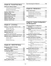
... Setting a Color Corrector 370 Setting an HDR Converter 370 Setting the Output Signal 373 Assigning an Output Signal 373 Selecting Outputs Configurable with a Color Corrector/HDR Converter 374 Setting Through Mode 374 Setting the Video Clip Function 375 Setting the Safe Title Area 375 Setting a Format Converter 376 Setting an HDR Converter 376 Setting 100G IP Input/Output Signals ... 377 Setting an ST 2110 Stream 377 Setting Multicasting 377 Setting the Audio Format...
... Setting a Color Corrector 370 Setting an HDR Converter 370 Setting the Output Signal 373 Assigning an Output Signal 373 Selecting Outputs Configurable with a Color Corrector/HDR Converter 374 Setting Through Mode 374 Setting the Video Clip Function 375 Setting the Safe Title Area 375 Setting a Format Converter 376 Setting an HDR Converter 376 Setting 100G IP Input/Output Signals ... 377 Setting an ST 2110 Stream 377 Setting Multicasting 377 Setting the Audio Format...
Users Guide
Page 11
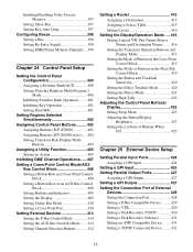
... Setting Key Auto Drop 397 Configuring Boxes 398 Setting a Bus 398 Setting Re-Entry Signals 398 Setting DME/Frame Memory Channels....399 Chapter 24 Control Panel Setup Setting the Control Panel Configuration 400 Assigning a Switcher Bank/AUX 400 Setting Switcher Banks in Multi Program 2 Mode 400 Inhibiting Switcher Bank Operation .........401 Inhibiting Key Operation 401 Setting Dual M/E 401 Setting Regions Selected Simultaneously 402 Assigning Control Panel Buttons .......... 402 Assigning Buttons...
... Setting Key Auto Drop 397 Configuring Boxes 398 Setting a Bus 398 Setting Re-Entry Signals 398 Setting DME/Frame Memory Channels....399 Chapter 24 Control Panel Setup Setting the Control Panel Configuration 400 Assigning a Switcher Bank/AUX 400 Setting Switcher Banks in Multi Program 2 Mode 400 Inhibiting Switcher Bank Operation .........401 Inhibiting Key Operation 401 Setting Dual M/E 401 Setting Regions Selected Simultaneously 402 Assigning Control Panel Buttons .......... 402 Assigning Buttons...
Users Guide
Page 12
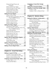
... Copy 437 Setting a Parallel Tally 438 Setting a Serial Tally 439 Chapter 27 Link Setup Setting a Cross-Point Button Link......... 440 Setting a Bus Link 440 Setting a Link Table 440 Setting an M/E Link 441 Setting a Key Link 442 Setting a Transition Link 442 Setting a Color Corrector Link Group ... 443 Setting a Bus and Destination Link....... 443 Setting a Matrix 443 Setting a Bus 443 Setting a Link Table 444 Chapter 28 100G IP I/F Setup Displaying 100G IP I/F Setup Information 445 Setting the Control Protocol 445 Configuring NMOS 446 Setting the Network...
... Copy 437 Setting a Parallel Tally 438 Setting a Serial Tally 439 Chapter 27 Link Setup Setting a Cross-Point Button Link......... 440 Setting a Bus Link 440 Setting a Link Table 440 Setting an M/E Link 441 Setting a Key Link 442 Setting a Transition Link 442 Setting a Color Corrector Link Group ... 443 Setting a Bus and Destination Link....... 443 Setting a Matrix 443 Setting a Bus 443 Setting a Link Table 444 Chapter 28 100G IP I/F Setup Displaying 100G IP I/F Setup Information 445 Setting the Control Protocol 445 Configuring NMOS 446 Setting the Network...
Users Guide
Page 13
... Archive File 487 Configuring MLS Manager 488 Setting the Date/Time in MLS Manager ...488 Displaying the MLS Manager Version .....489 Managing MLS Manager Users 489 MLS Manager Log Information 490 Appendix Wipe Pattern List 491 Wipe Pattern List 491 DME Wipe Pattern List 492 Resizer DME Wipe Pattern List 496 Menus Recalled by Pressing a Button Twice 497 Number of Switcher Resources 501 Input/Output Numbers 503...
... Archive File 487 Configuring MLS Manager 488 Setting the Date/Time in MLS Manager ...488 Displaying the MLS Manager Version .....489 Managing MLS Manager Users 489 MLS Manager Log Information 490 Appendix Wipe Pattern List 491 Wipe Pattern List 491 DME Wipe Pattern List 492 Resizer DME Wipe Pattern List 496 Menus Recalled by Pressing a Button Twice 497 Number of Switcher Resources 501 Input/Output Numbers 503...
Users Guide
Page 16
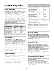
... Box IDs Boxes in an island. Island configuration 5-box configuration 4-box configuration 3-box configuration 2-box configuration 1-box configuration Cross-point box 1 unit 1 unit 1 unit 1 unit - This document refers to as simply a box. The access destination of the MLS-X1 menu and the storage destination for managing the system configuration of boxes. The cross-point box and M/E boxes are connected together using the following combination of MLS-X1 boxes with ICP-X1000-series/X7000-series control panels...
... Box IDs Boxes in an island. Island configuration 5-box configuration 4-box configuration 3-box configuration 2-box configuration 1-box configuration Cross-point box 1 unit 1 unit 1 unit 1 unit - This document refers to as simply a box. The access destination of the MLS-X1 menu and the storage destination for managing the system configuration of boxes. The cross-point box and M/E boxes are connected together using the following combination of MLS-X1 boxes with ICP-X1000-series/X7000-series control panels...
Users Guide
Page 59
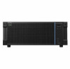
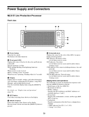
... 5 seconds c Display Displays the box model, settings, and other information. Lit green during normal operation. Normal operation: Lit blue While starting/shutting down/updating firmware: Flashing When an error occurs: Lit red When a warning occurs: Lit amber When beacon is lit when turned on /off. REF indicator: Reference status Lit red when an error occurs. Power Supply and Connectors MLS-X1 Live Production Processor Front view a bc d e f a Power button Turns the box on .
... 5 seconds c Display Displays the box model, settings, and other information. Lit green during normal operation. Normal operation: Lit blue While starting/shutting down/updating firmware: Flashing When an error occurs: Lit red When a warning occurs: Lit amber When beacon is lit when turned on /off. REF indicator: Reference status Lit red when an error occurs. Power Supply and Connectors MLS-X1 Live Production Processor Front view a bc d e f a Power button Turns the box on .

Users Guide
Page 62
...) Outputs the internal reference signal when an external reference signal is installed. h connector (USB 3.0, Type A) Connect to 1 depending on the product. i connector (USB 2.0, Type A) Connect to a USB device such as interface expansion 1 to an external reference signal. k AC IN A, B, C, D connectors Connect to an AC power supply using the unit synchronized to 4 LAN connectors. For details, see "Configuring Box Network Settings" (page 470). Used as a USB drive or keyboard. d LAN...
...) Outputs the internal reference signal when an external reference signal is installed. h connector (USB 3.0, Type A) Connect to 1 depending on the product. i connector (USB 2.0, Type A) Connect to a USB device such as interface expansion 1 to an external reference signal. k AC IN A, B, C, D connectors Connect to an AC power supply using the unit synchronized to 4 LAN connectors. For details, see "Configuring Box Network Settings" (page 470). Used as a USB drive or keyboard. d LAN...
Users Guide
Page 68
....1" by default. 2 Download a root certificate. 3 Install the root certificate. For details about settings, see "Configuring Box Network Settings" (page 470). Menu Operation 3 Chapter Overview The MLS-X1 menu is used , such as the IP address of the certificate download page. • IP address displayed on the control panel display • Address of standard interface 1 of logical box 1 (primary box) of the corresponding logical switcher, which is recommended that can be connected simultaneously...
....1" by default. 2 Download a root certificate. 3 Install the root certificate. For details about settings, see "Configuring Box Network Settings" (page 470). Menu Operation 3 Chapter Overview The MLS-X1 menu is used , such as the IP address of the certificate download page. • IP address displayed on the control panel display • Address of standard interface 1 of logical box 1 (primary box) of the corresponding logical switcher, which is recommended that can be connected simultaneously...
Users Guide
Page 69
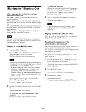
... time using the display and buttons on the control panel display • Address of standard interface 1 of logical box 1 (primary box) of the MLS-X1 menu in the header area and select [Sign Out] from the MLS-X1 menu Press the overflow button in a browser. Signing out from the pull-down list. The display item changes each time the [SELECT] button is reset. The password is pressed. 2 Press the [SET] button. The software End User...
... time using the display and buttons on the control panel display • Address of standard interface 1 of logical box 1 (primary box) of the MLS-X1 menu in the header area and select [Sign Out] from the MLS-X1 menu Press the overflow button in a browser. Signing out from the pull-down list. The display item changes each time the [SELECT] button is reset. The password is pressed. 2 Press the [SET] button. The software End User...
Users Guide
Page 74
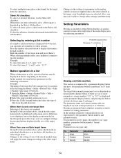
... all items, clear the check mark from the pull-down list. Setting Parameters Pressing a parameter setting button displays an analog controls section on each of the menu display area for an item in the analog controls section are represented by entering a list number If a number selection button is not required. In this manual, list item button operations use the following convention. To select multiple items, place a check...
... all items, clear the check mark from the pull-down list. Setting Parameters Pressing a parameter setting button displays an analog controls section on each of the menu display area for an item in the analog controls section are represented by entering a list number If a number selection button is not required. In this manual, list item button operations use the following convention. To select multiple items, place a check...
Users Guide
Page 178
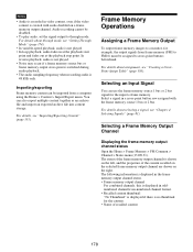
... play audio, set the signal output to cross-point buttons beforehand. The following information is displayed in the frame memory output channel status. • Frame memory output channel For combined channels, this is displayed in oddnumbered channel/even-numbered channel format. • Recalled content thumbnail "No Thumbnail" is displayed if there is no thumbnail for example, the output signals from a computer using the Home > Content > Import/Export menu...
... play audio, set the signal output to cross-point buttons beforehand. The following information is displayed in the frame memory output channel status. • Frame memory output channel For combined channels, this is displayed in oddnumbered channel/even-numbered channel format. • Recalled content thumbnail "No Thumbnail" is displayed if there is no thumbnail for example, the output signals from a computer using the Home > Content > Import/Export menu...
Users Guide
Page 237
... the transition control block display. Note You can also automatically change the operation mode configuration data saved in a register when copy/move/ swap operations are shown on the sub side is supported using the delegation buttons in the Common > Key Priority/Key Assign menu of the program 1 output to program 4 output are added to the main side, press the [MAIN] button, turning it...
... the transition control block display. Note You can also automatically change the operation mode configuration data saved in a register when copy/move/ swap operations are shown on the sub side is supported using the delegation buttons in the Common > Key Priority/Key Assign menu of the program 1 output to program 4 output are added to the main side, press the [MAIN] button, turning it...
Users Guide
Page 280
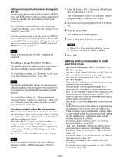
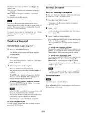
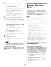
... hold the [SNAPSHOT] button and press the button for the target register. To add the auto transition temporary attribute Press the [AUTO TRANS] button, turning it on orange, and press the register button. To add the auto transition attribute Press and hold the [SNAPSHOT] button and press the [EFF DISS] button, then continue pressing the [SNAPSHOT] button and press a register button. The register number is recalled. The...
... hold the [SNAPSHOT] button and press the button for the target register. To add the auto transition temporary attribute Press the [AUTO TRANS] button, turning it on orange, and press the register button. To add the auto transition attribute Press and hold the [SNAPSHOT] button and press the [EFF DISS] button, then continue pressing the [SNAPSHOT] button and press a register button. The register number is recalled. The...
Users Guide
Page 282
... setting an attribute, see "Selecting a region" (page 255). Note If you press a register button in which a snapshot is displayed on the display on the [Effect Timeline Edit] taskbar - [Edit Macro Event] window: Displayed using the region selection buttons. Notes • Multiple simultaneous MLS-X1 menu session connections are linked. This section describes the M/E-1 menu as in the memory recall section of the Flexi Pad control...
... setting an attribute, see "Selecting a region" (page 255). Note If you press a register button in which a snapshot is displayed on the display on the [Effect Timeline Edit] taskbar - [Edit Macro Event] window: Displayed using the region selection buttons. Notes • Multiple simultaneous MLS-X1 menu session connections are linked. This section describes the M/E-1 menu as in the memory recall section of the Flexi Pad control...
Users Guide
Page 365
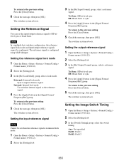
... signal is configured using MLS Manager. Tri Sync: HD tri-level sync BB: Black burst or sync 4 Press the [Apply] button in the [Signal Format/ Frequency/Ref] group. Setting the output reference signal 1 Open the Home > Setup > System > Format/Config > Format menu (19101.22). 2 Select the [Settings] tab. 3 In the [Ref Output Format] group, select a reference signal. The switcher system reboots. Internal: Internal lock mode Use switcher internal signal...
... signal is configured using MLS Manager. Tri Sync: HD tri-level sync BB: Black burst or sync 4 Press the [Apply] button in the [Signal Format/ Frequency/Ref] group. Setting the output reference signal 1 Open the Home > Setup > System > Format/Config > Format menu (19101.22). 2 Select the [Settings] tab. 3 In the [Ref Output Format] group, select a reference signal. The switcher system reboots. Internal: Internal lock mode Use switcher internal signal...
Users Guide
Page 366
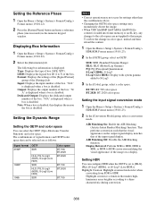
....2020 color space Setting the input signal conversion mode 1 Open the Home > Setup > System > Format/Config > HDR/SDR Format menu (19101.23). 2 In the [Conversion Mode] group, select a conversion mode. "N/A" is displayed when a box is displayed. AIR Matching On: Enable the AIR Matching (Artistic Intent Render Matching) function. Setting the Reference Phase 1 Open the Home > Setup > System > Format/Config > Format menu (19101.22). 2 Press the [System Phase] button and...
....2020 color space Setting the input signal conversion mode 1 Open the Home > Setup > System > Format/Config > HDR/SDR Format menu (19101.23). 2 In the [Conversion Mode] group, select a conversion mode. "N/A" is displayed when a box is displayed. AIR Matching On: Enable the AIR Matching (Artistic Intent Render Matching) function. Setting the Reference Phase 1 Open the Home > Setup > System > Format/Config > Format menu (19101.22). 2 Press the [System Phase] button and...
Users Guide
Page 376
... (Live HDR)]. 5 Press the [Color] button and select a color space from the pull-down list. If the system settings are displayed in unison. 376 Apply the system settings to the output signal. Note When multiple outputs are given below. For details about outputs that can be configured with a Color Corrector/HDR Converter" (page 374). Note To use a format converter on odd-numbered outputs...
... (Live HDR)]. 5 Press the [Color] button and select a color space from the pull-down list. If the system settings are displayed in unison. 376 Apply the system settings to the output signal. Note When multiple outputs are given below. For details about outputs that can be configured with a Color Corrector/HDR Converter" (page 374). Note To use a format converter on odd-numbered outputs...
Users Guide
Page 453
...) is displayed on the network. You can be copied to "Local" (Color Settings on the switcher from the list of remote panels connected to connect. To return to 8 are displayed. Setting a Network AUX Remote Panel Network AUX remote panel A network AUX remote panel is a function that provides a simple connection of an MKS-R3210/R1620 Remote Control Panel with a switcher, without using LSM (Live System Manager), for using the [Aux Remote Interface] button. Network AUX remote panel restrictions...
...) is displayed on the network. You can be copied to "Local" (Color Settings on the switcher from the list of remote panels connected to connect. To return to 8 are displayed. Setting a Network AUX Remote Panel Network AUX remote panel A network AUX remote panel is a function that provides a simple connection of an MKS-R3210/R1620 Remote Control Panel with a switcher, without using LSM (Live System Manager), for using the [Aux Remote Interface] button. Network AUX remote panel restrictions...
Users Guide
Page 472
...) using the keyboard. 8 Press [OK]. 472 Setting the default gateway of a box 1 Open the MLS Manager Home > System > Island > Box Network menu (60211.05). 2 In the [Box] group list, select the target box to set to [Off], [Auto], or [DHCP], proceed to the selected LAN setting. Note When multiple network interfaces are selected, consecutively numbered IP addresses are selected, the same value is linked to step 8. 7 Press the [Address] button...
...) using the keyboard. 8 Press [OK]. 472 Setting the default gateway of a box 1 Open the MLS Manager Home > System > Island > Box Network menu (60211.05). 2 In the [Box] group list, select the target box to set to [Off], [Auto], or [DHCP], proceed to the selected LAN setting. Note When multiple network interfaces are selected, consecutively numbered IP addresses are selected, the same value is linked to step 8. 7 Press the [Address] button...
Users Guide
Page 478
... Network I /F] group list, select a network interface other than standard interface 1 of LAN which can only be set manually. 5 Press the [Address] button for redundancy is set (multiple selection supported). To set an interface other than standard interface 1 (STD 1) 1 Open the MLS Manager Home > System > Off-Island > Box Network menu (60219.01). 2 Press the [Detect/Refresh] button. Off: Do not use IPv4. DHCP: Set automatically using DHCP. When [Off], [Auto...
... Network I /F] group list, select a network interface other than standard interface 1 of LAN which can only be set manually. 5 Press the [Address] button for redundancy is set (multiple selection supported). To set an interface other than standard interface 1 (STD 1) 1 Open the MLS Manager Home > System > Off-Island > Box Network menu (60219.01). 2 Press the [Detect/Refresh] button. Off: Do not use IPv4. DHCP: Set automatically using DHCP. When [Off], [Auto...


