Child Safety: It Makes A Difference Where Your TV Stands
Page 1
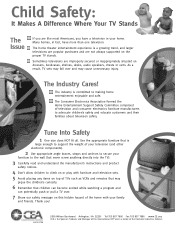
Sometimes televisions are like most Americans, you have more than one television. Thank you! 2500 Wilson Boulevard Arlington, VA 22201 Tel 703 907 7600 Fax 703 907 7690 www.CE.org CEA is the Sponsor, Producer and Manager of the Electronic Industries Alliance The Industry Cares! Child Safety: It Makes A Difference Where Your TV Stands The Issue If you are improperly secured or inappropriately situated on dressers, bookcases, shelves, desks, audio speakers, chests or carts. Many homes, in fact, have a television in your family and friends. The home theater entertainment ...
Sometimes televisions are like most Americans, you have more than one television. Thank you! 2500 Wilson Boulevard Arlington, VA 22201 Tel 703 907 7600 Fax 703 907 7690 www.CE.org CEA is the Sponsor, Producer and Manager of the Electronic Industries Alliance The Industry Cares! Child Safety: It Makes A Difference Where Your TV Stands The Issue If you are improperly secured or inappropriately situated on dressers, bookcases, shelves, desks, audio speakers, chests or carts. Many homes, in fact, have a television in your family and friends. The home theater entertainment ...

Limited Warranty (U.S. Only)
Page 1
... or modification of, or to any Sony authorized service facility. has established telephone numbers for a period of protection, to any authorized Sony service facility. 4-557-168-03 ® LIMITED WARRANTY HDTV Color TV XBR Projection TV Sony Electronics Inc. ("Sony") warrants this Product is determined to be...LABOR: For a period of sale or receipted invoice which vary from your convenience, Sony Electronics Inc. This warranty is valid only in the form of a bill of one (1) year (color picture tube - REPAIR OR REPLACEMENT AS PROVIDED UNDER THIS WARRANTY IS THE EXCLUSIVE ...
... or modification of, or to any Sony authorized service facility. has established telephone numbers for a period of protection, to any authorized Sony service facility. 4-557-168-03 ® LIMITED WARRANTY HDTV Color TV XBR Projection TV Sony Electronics Inc. ("Sony") warrants this Product is determined to be...LABOR: For a period of sale or receipted invoice which vary from your convenience, Sony Electronics Inc. This warranty is valid only in the form of a bill of one (1) year (color picture tube - REPAIR OR REPLACEMENT AS PROVIDED UNDER THIS WARRANTY IS THE EXCLUSIVE ...

Operating Instructions
Page 1
4-077-172-11(1) Color Rear Video Projector Operating Instructions KP-48V85 KP-53V85 KP-61V85 © 2000 Sony Corporation
4-077-172-11(1) Color Rear Video Projector Operating Instructions KP-48V85 KP-53V85 KP-61V85 © 2000 Sony Corporation
Operating Instructions
Page 2
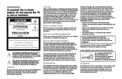
...different from the broadcaster/cable company and/or program owner. Note to the point of misuse. As an ENERGY STAR Partner, Sony Corporation has determined that this notice with your authority to provide reasonable protection against harmful interference in the literature accompanying the appliance. ...extension cord, receptacle or other than private viewing of programs broadcast on the screen for the remote control RM-Y905 MODELS: KP-48V85, KP-53V85, KP-61V85 Please keep the brightness and contrast functions at a high brightness or contrast setting, the image can be determined by...
...different from the broadcaster/cable company and/or program owner. Note to the point of misuse. As an ENERGY STAR Partner, Sony Corporation has determined that this notice with your authority to provide reasonable protection against harmful interference in the literature accompanying the appliance. ...extension cord, receptacle or other than private viewing of programs broadcast on the screen for the remote control RM-Y905 MODELS: KP-48V85, KP-53V85, KP-61V85 Please keep the brightness and contrast functions at a high brightness or contrast setting, the image can be determined by...
Operating Instructions
Page 3
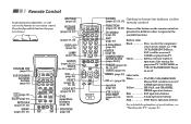
...GUIDE (page 57) projection TV, SAT/CABLE, or VTR (VCR)/MDP/DVD Player on or off MENU (page 33) Label color White TV/VTR (VCR)/MDP/DVD CH +/- (page 25) Player/SAT (satellite receiver)/ Joystick (page 22) CABLE operation ...(page 27) 0-9 buttons (page 25) ENTER (page 25) CHANNEL INDEX/ PIP/P&P/ACTIVE (pages 28-32) Button color Black Press to select the component you want to control; VTR (VCR)/MDP/DVD Player, SAT (satellite receiver)/ CABLE,... will refer to the buttons on the remote control are TV/VIDEO (page 26) presented in different colors to represent the available functions.
...GUIDE (page 57) projection TV, SAT/CABLE, or VTR (VCR)/MDP/DVD Player on or off MENU (page 33) Label color White TV/VTR (VCR)/MDP/DVD CH +/- (page 25) Player/SAT (satellite receiver)/ Joystick (page 22) CABLE operation ...(page 27) 0-9 buttons (page 25) ENTER (page 25) CHANNEL INDEX/ PIP/P&P/ACTIVE (pages 28-32) Button color Black Press to select the component you want to control; VTR (VCR)/MDP/DVD Player, SAT (satellite receiver)/ CABLE,... will refer to the buttons on the remote control are TV/VIDEO (page 26) presented in different colors to represent the available functions.
Operating Instructions
Page 4
...Connecting two VCRs for tape editing 15 Connecting a DVD Player 16 Connecting a DVD Player with component video output connectors 16 Connecting an AV receiver 17 Connecting an audio system 18 Connecting a Sony SAVA series speaker system 18 Connecting an amplifier that supports Dolby Pro Logic decoder 19 Using the ...One Time - P&P (Twin ViewTM 30 Using CHANNEL INDEX 32 Adjusting Your SET UP (menus) ... 33 Learning Menu Selection 33 Using the Video Menu 34 Using the Audio Menu 35 Using the Timer Menu 37 ch Using the Channel Set Up Menu ...... 38 Setting and Selecting Favorite Channel...
...Connecting two VCRs for tape editing 15 Connecting a DVD Player 16 Connecting a DVD Player with component video output connectors 16 Connecting an AV receiver 17 Connecting an audio system 18 Connecting a Sony SAVA series speaker system 18 Connecting an amplifier that supports Dolby Pro Logic decoder 19 Using the ...One Time - P&P (Twin ViewTM 30 Using CHANNEL INDEX 32 Adjusting Your SET UP (menus) ... 33 Learning Menu Selection 33 Using the Video Menu 34 Using the Audio Menu 35 Using the Timer Menu 37 ch Using the Channel Set Up Menu ...... 38 Setting and Selecting Favorite Channel...
Operating Instructions
Page 5
...Sony logo, on the sticker, and also on the TV box (white label). Manufactured under license from eight of SRS Labs, Inc. 1 Patent No. 4,748,669. Record these numbers in Canada 53 Operating Video...video or cable image as a window picture. • CHANNEL INDEX, allowing you to view and choose from twelve programs • Favorite Channel, allowing you feel are located at the rear of Dolby Laboratories Licensing Corporation. Serial No. Model KP-53V85... SYSTEM) is used for purchasing the Sony Color Rear Video Projection TV. Additionally licensed under license from SRS Labs, Inc.
...Sony logo, on the sticker, and also on the TV box (white label). Manufactured under license from eight of SRS Labs, Inc. 1 Patent No. 4,748,669. Record these numbers in Canada 53 Operating Video...video or cable image as a window picture. • CHANNEL INDEX, allowing you to view and choose from twelve programs • Favorite Channel, allowing you feel are located at the rear of Dolby Laboratories Licensing Corporation. Serial No. Model KP-53V85... SYSTEM) is used for purchasing the Sony Color Rear Video Projection TV. Additionally licensed under license from SRS Labs, Inc.
Operating Instructions
Page 6
... your new projection TV, including Auto Set Up. If you how to let the moisture evaporate before operating it may be blurred or show poor color.
... your new projection TV, including Auto Set Up. If you how to let the moisture evaporate before operating it may be blurred or show poor color.
Operating Instructions
Page 7
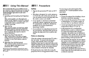
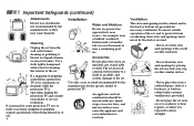
Use Power Sources This set should be operated only from the type of power source indicated on the set. (continued) 3 For those sets designed to operate from the wall outlet as they may touch dangerous voltage points or short out parts that could result in . If you are unable to insert the plug into the outlet, contact your electrician to have a suitable outlet installed. This is a safety feature. Overloading Do not overload wall outlets, extension cords or convenience receptacles beyond their capacity, since this manual for future reference. When the set through the cabinet slots ...
Use Power Sources This set should be operated only from the type of power source indicated on the set. (continued) 3 For those sets designed to operate from the wall outlet as they may touch dangerous voltage points or short out parts that could result in . If you are unable to insert the plug into the outlet, contact your electrician to have a suitable outlet installed. This is a safety feature. Overloading Do not overload wall outlets, extension cords or convenience receptacles beyond their capacity, since this manual for future reference. When the set through the cabinet slots ...
Operating Instructions
Page 8
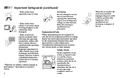
If a snapping or popping sound from a projection TV set is continuous or frequent while the projection TV is provided. - Ventilation The slots and openings in the cabinet and in the back or bottom are provided for cleaning the exterior of the set in a confined space, such as they may cause hazards. Never place the set . Quick stops, excessive force, and uneven surfaces may fall, causing serious injury to a child or an adult, and serious damage to the set on a bed, sofa, rug or other materials. - Use a cloth lightly dampened with water for necessary ventilation. Never ...
If a snapping or popping sound from a projection TV set is continuous or frequent while the projection TV is provided. - Ventilation The slots and openings in the cabinet and in the back or bottom are provided for cleaning the exterior of the set in a confined space, such as they may cause hazards. Never place the set . Quick stops, excessive force, and uneven surfaces may fall, causing serious injury to a child or an adult, and serious damage to the set on a bed, sofa, rug or other materials. - Use a cloth lightly dampened with water for necessary ventilation. Never ...
Operating Instructions
Page 9
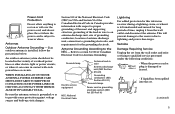
If an outdoor antenna is damaged or frayed. - Section 810 of the National Electrical Code (NEC) in USA and Section 54 of the Canadian Electrical Code in Canada provides information with such power lines or circuits. This will prevent damage to the receiver due to the NEC - WHEN INSTALLING AN OUTDOOR ANTENNA SYSTEM, EXTREME CARE SHOULD BE TAKEN TO KEEP FROM CONTACTING SUCH POWER LINES OR CIRCUITS AS CONTACT WITH THEM IS ALMOST INVARIABLY FATAL. Refer to section 54-300 of overhead power lines or other electric light or power circuits, or where it from the wall outlet and refer ...
If an outdoor antenna is damaged or frayed. - Section 810 of the National Electrical Code (NEC) in USA and Section 54 of the Canadian Electrical Code in Canada provides information with such power lines or circuits. This will prevent damage to the receiver due to the NEC - WHEN INSTALLING AN OUTDOOR ANTENNA SYSTEM, EXTREME CARE SHOULD BE TAKEN TO KEEP FROM CONTACTING SUCH POWER LINES OR CIRCUITS AS CONTACT WITH THEM IS ALMOST INVARIABLY FATAL. Refer to section 54-300 of overhead power lines or other electric light or power circuits, or where it from the wall outlet and refer ...
Operating Instructions
Page 10
Adjust only those controls that are required, be sure the service technician certifies in writing that he has used replacement parts specified by a qualified technician to restore the set is in safe operating condition, and to dangerous voltage or other hazards. When the set exhibits a distinct change in performance-this indicates a need for service. 6 Servicing Do not attempt to service the set yourself since opening the cabinet may result in the operating instructions. Replacement Parts When replacement parts are specified in damage and will often require extensive work by ...
Adjust only those controls that are required, be sure the service technician certifies in writing that he has used replacement parts specified by a qualified technician to restore the set is in safe operating condition, and to dangerous voltage or other hazards. When the set exhibits a distinct change in performance-this indicates a need for service. 6 Servicing Do not attempt to service the set yourself since opening the cabinet may result in the operating instructions. Replacement Parts When replacement parts are specified in damage and will often require extensive work by ...
Operating Instructions
Page 11
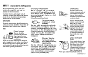
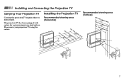
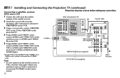
Installing the Projection TV Recommended viewing area (Vertical) Recommended viewing area (Horizontal) min. 60° 1.8m48("amppinr.o2x..16m5f3t(."a)mppinro. 2x..47m6f1t(."a)pprox. 8 ft.) mmmiiinnn...122...814mmm4568(31((a"aa""pppppprrroooxxx...678fffttt...))) 20° 60° 20° 7 Installing and Connecting the Projection TV Carrying Your Projection TV Carrying the projection TV requires three or more people. The projection TV has been equipped with casters for easy movement on a hard surface. Please move your projection TV using the casters.
Installing the Projection TV Recommended viewing area (Vertical) Recommended viewing area (Horizontal) min. 60° 1.8m48("amppinr.o2x..16m5f3t(."a)mppinro. 2x..47m6f1t(."a)pprox. 8 ft.) mmmiiinnn...122...814mmm4568(31((a"aa""pppppprrroooxxx...678fffttt...))) 20° 60° 20° 7 Installing and Connecting the Projection TV Carrying Your Projection TV Carrying the projection TV requires three or more people. The projection TV has been equipped with casters for easy movement on a hard surface. Please move your projection TV using the casters.
Operating Instructions
Page 12
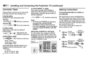
...Rear of projection TV) CONTROL S OUT IN VIDEO 1 VIDEO 3 VIDEO 4 VIDEO 5 S VIDEO CENTER SPEAKER IN VIDEO 40W(NOM) 80W(MAX)16 L (MONO) AUDIO R Y PB PR L AUDIO R OUT TV MONITOR AUDIO (VAR/FIX) VIDEO L (MONO) AUDIO R CONTROL S OUT S-LINK VIDEO 1 VIDEO 3 VIDEO 4 IN VIDEO 5 S-LINK AUDIO TV MONITOR (VAR/FIX) OUT Making Connections Connecting directly to Sony...VHF/UHF or • Cable (Rear of projection TV) VHF/UHF B (Rear of the following three video connectors. Note: • For S-Link and CONTROL S connections, you can use some Sony video equipment, or you choose will ...
...Rear of projection TV) CONTROL S OUT IN VIDEO 1 VIDEO 3 VIDEO 4 VIDEO 5 S VIDEO CENTER SPEAKER IN VIDEO 40W(NOM) 80W(MAX)16 L (MONO) AUDIO R Y PB PR L AUDIO R OUT TV MONITOR AUDIO (VAR/FIX) VIDEO L (MONO) AUDIO R CONTROL S OUT S-LINK VIDEO 1 VIDEO 3 VIDEO 4 IN VIDEO 5 S-LINK AUDIO TV MONITOR (VAR/FIX) OUT Making Connections Connecting directly to Sony...VHF/UHF or • Cable (Rear of projection TV) VHF/UHF B (Rear of the following three video connectors. Note: • For S-Link and CONTROL S connections, you can use some Sony video equipment, or you choose will ...
Operating Instructions
Page 13
...Cable" to the projection TV. (Rear of projection TV) Coaxial cable VHF/UHF (Rear of projection TV) Coaxial cable AUX (No connection "TO CONVERTER" in the main picture. 9 Notes: • You may find it convenient to use the following set up if your Sony remote control to receive using an antenna.... Coaxial cable (Rear of projection TV) VHF/UHF IN OUT *Cable box Cable box and cable Some pay cable TV systems use scrambled...
...Cable" to the projection TV. (Rear of projection TV) Coaxial cable VHF/UHF (Rear of projection TV) Coaxial cable AUX (No connection "TO CONVERTER" in the main picture. 9 Notes: • You may find it convenient to use the following set up if your Sony remote control to receive using an antenna.... Coaxial cable (Rear of projection TV) VHF/UHF IN OUT *Cable box Cable box and cable Some pay cable TV systems use scrambled...
Operating Instructions
Page 14
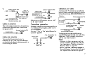
... any connections. (Rear of projection TV) IN VIDEO 1 VIDEO 3 VIDEO 4 VIDEO 5 AUX S VIDEO Y PB OUT TV MONITOR AUDIO (VAR/FIX) TO CONVERTER VIDEO L (MONO) AUDIO R PR L AUDIO R VIDEO L (MONO) AUDIO R VHF/UHF 2 Coaxial cable VCR S-LINK VIDEO 1 VIDEO 3 VIDEO 4 IN VIDEO 5 S-LINK VIDEO AUDIO-L AUDIO-R AUDIO TV MONITOR (VAR/FIX) OUT VMC-810S/820S (not supplied) AUDIO R AUDIO L VIDEO LINE IN S VIDEO LINE OUT YC...
... any connections. (Rear of projection TV) IN VIDEO 1 VIDEO 3 VIDEO 4 VIDEO 5 AUX S VIDEO Y PB OUT TV MONITOR AUDIO (VAR/FIX) TO CONVERTER VIDEO L (MONO) AUDIO R PR L AUDIO R VIDEO L (MONO) AUDIO R VHF/UHF 2 Coaxial cable VCR S-LINK VIDEO 1 VIDEO 3 VIDEO 4 IN VIDEO 5 S-LINK VIDEO AUDIO-L AUDIO-R AUDIO TV MONITOR (VAR/FIX) OUT VMC-810S/820S (not supplied) AUDIO R AUDIO L VIDEO LINE IN S VIDEO LINE OUT YC...
Operating Instructions
Page 15
... projection TV (White-AUDIO Left, Red-AUDIO Right). Disconnect all power sources before making any connections. (Rear of the S VIDEO cable. ** If you are connecting a monaural VCR, connect only the single audio output to by pressing TV/ VIDEO on the projection TV. Connecting a satellite receiver (SAT) 1 Connect the cable from the satellite antenna...
... projection TV (White-AUDIO Left, Red-AUDIO Right). Disconnect all power sources before making any connections. (Rear of the S VIDEO cable. ** If you are connecting a monaural VCR, connect only the single audio output to by pressing TV/ VIDEO on the projection TV. Connecting a satellite receiver (SAT) 1 Connect the cable from the satellite antenna...
Operating Instructions
Page 16
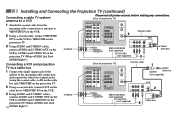
... on the remote control. YC-15V/30V (not supplied) Cable/ Antenna 12 S VIDEO (Rear of projection TV) IN VIDEO 1 VIDEO 3 VIDEO 4 VIDEO 5 S VIDEO VIDEO L (MONO) AUDIO R Y PB PR L AUDIO R OUT TV MONITOR AUDIO (VAR/FIX) VIDEO L (MONO) AUDIO R S-LINK VIDEO 1 VIDEO 3 VIDEO 4 IN VIDEO 5 S-LINK AUDIO TV MONITOR (VAR/FIX) OUT VIDEO AUDIO-L AUDIO-R 3 AUX Coaxial cable TO CONVERTER SATELLITE IN SAT VHF/UHF...
... on the remote control. YC-15V/30V (not supplied) Cable/ Antenna 12 S VIDEO (Rear of projection TV) IN VIDEO 1 VIDEO 3 VIDEO 4 VIDEO 5 S VIDEO VIDEO L (MONO) AUDIO R Y PB PR L AUDIO R OUT TV MONITOR AUDIO (VAR/FIX) VIDEO L (MONO) AUDIO R S-LINK VIDEO 1 VIDEO 3 VIDEO 4 IN VIDEO 5 S-LINK AUDIO TV MONITOR (VAR/FIX) OUT VIDEO AUDIO-L AUDIO-R 3 AUX Coaxial cable TO CONVERTER SATELLITE IN SAT VHF/UHF...
Operating Instructions
Page 17
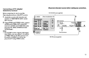
... Left, RedAUDIO Right). YC-15V/30V (not supplied) S VIDEO (Rear of projection TV) IN VIDEO 1 VIDEO 3 VIDEO 4 VIDEO 5 S VIDEO VIDEO L (MONO) AUDIO R Y PB PR L AUDIO R OUT TV MONITOR AUDIO (VAR/FIX) VIDEO L (MONO) AUDIO R S-LINK VIDEO 1 VIDEO 3 VIDEO 4 IN VIDEO 5 S-LINK AUDIO TV MONITOR (VAR/FIX) OUT AUDIO-R ...1 VCR LOW SPEED DATA CONTROL Roof antenna RK-74A (not supplied) 2 VIDEO 1 2 3 ACCESS CARD S VIDEO Y DIGITAL AUDIO OUT L PB (OPTICAL) MONO R PR VGA OUT AUDIO AUDIO/VIDEO OUT TEL LINE 2 13 Disconnect all power sources before making any connections. ...
... Left, RedAUDIO Right). YC-15V/30V (not supplied) S VIDEO (Rear of projection TV) IN VIDEO 1 VIDEO 3 VIDEO 4 VIDEO 5 S VIDEO VIDEO L (MONO) AUDIO R Y PB PR L AUDIO R OUT TV MONITOR AUDIO (VAR/FIX) VIDEO L (MONO) AUDIO R S-LINK VIDEO 1 VIDEO 3 VIDEO 4 IN VIDEO 5 S-LINK AUDIO TV MONITOR (VAR/FIX) OUT AUDIO-R ...1 VCR LOW SPEED DATA CONTROL Roof antenna RK-74A (not supplied) 2 VIDEO 1 2 3 ACCESS CARD S VIDEO Y DIGITAL AUDIO OUT L PB (OPTICAL) MONO R PR VGA OUT AUDIO AUDIO/VIDEO OUT TEL LINE 2 13 Disconnect all power sources before making any connections. ...
Operating Instructions
Page 18
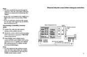
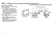
...the front of projection TV) Camcorder 14 Use this connection to view a picture directly from a camcorder. S VIDEO VIDEO L AUDIO R (MONO) VIDEO 2 INPUT * If your camcorder. Installing and Connecting the Projection TV (continued) Connecting a camcorder Disconnect all power sources ...before making any connections. S VIDEO VMC-810S/820S (not supplied) VIDEO AUDIO-L AUDIO-R Audio/ video outputs S VIDEO OUT 2 Press VIDEO 2 to AUDIO and S VIDEO IN inside the drop-down panel on the projection TV. (Front of the ...
...the front of projection TV) Camcorder 14 Use this connection to view a picture directly from a camcorder. S VIDEO VIDEO L AUDIO R (MONO) VIDEO 2 INPUT * If your camcorder. Installing and Connecting the Projection TV (continued) Connecting a camcorder Disconnect all power sources ...before making any connections. S VIDEO VMC-810S/820S (not supplied) VIDEO AUDIO-L AUDIO-R Audio/ video outputs S VIDEO OUT 2 Press VIDEO 2 to AUDIO and S VIDEO IN inside the drop-down panel on the projection TV. (Front of the ...