Revision History
Page 3
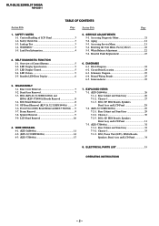
... OF CONTENTS Section Title Page Section Title Page 1. Safety Check Out 3 1-3. Overview of LCD Panel 3 1-2. Rear Cover Removal 7 3-2. GP Board Removal (KLV-26,32,32/H/S S400A 9 3-6. Speaker Removal 9 3-9. Caution Handling of Control Buttons 5 2-2. SELF DIAGNOSTIC... GP, HG4 Boards, Speakers, Bezel Assy and LCD Panel 28 7-2. (KLV-32,32/H/S S400A 29 7-2-1. ELECTRICAL PARTS LIST 35 OPERATING INSTRUCTIONS - 2 - LED Display Control 5 2-4. Frame Removal 9 3-8. WIRE DRESSING 4-1. (KLV-26S400A 11 4-2. (KLV-32,32/H/S S400A 14 4-3. (KLV-37S400A 17 7. Chassis...
... OF CONTENTS Section Title Page Section Title Page 1. Safety Check Out 3 1-3. Overview of LCD Panel 3 1-2. Rear Cover Removal 7 3-2. GP Board Removal (KLV-26,32,32/H/S S400A 9 3-6. Speaker Removal 9 3-9. Caution Handling of Control Buttons 5 2-2. SELF DIAGNOSTIC... GP, HG4 Boards, Speakers, Bezel Assy and LCD Panel 28 7-2. (KLV-32,32/H/S S400A 29 7-2-1. ELECTRICAL PARTS LIST 35 OPERATING INSTRUCTIONS - 2 - LED Display Control 5 2-4. Frame Removal 9 3-8. WIRE DRESSING 4-1. (KLV-26S400A 11 4-2. (KLV-32,32/H/S S400A 14 4-3. (KLV-37S400A 17 7. Chassis...
Revision History
Page 4
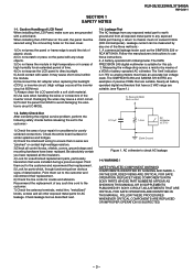
...COMPONENTS WITH SONY PARTS WHOSE PART NUMBERS APPEAR AS SHOWN IN THIS MANUAL OR IN SUPPLEMENTS PUBLISHED BY SONY. Caution...LCD panel with a wrist band. Safety Check-Out After correcting the original service problem, perform the following safety checks before releasing the set to avoid damaging the electronic circuit (C-MOS). 1-3. WARNING ! FOLLOW THESE PROCEDURES WHENEVER CRITICAL COMPONENTS ARE REPLACED OR IMPROPER OPERATION IS SUSPECTED. - 3 - KLV-26,32,32...avoid the risk of LCD Panel When installing the LCD Panel, make sure you have an accurate low voltage scale. Check leakage ...
...COMPONENTS WITH SONY PARTS WHOSE PART NUMBERS APPEAR AS SHOWN IN THIS MANUAL OR IN SUPPLEMENTS PUBLISHED BY SONY. Caution...LCD panel with a wrist band. Safety Check-Out After correcting the original service problem, perform the following safety checks before releasing the set to avoid damaging the electronic circuit (C-MOS). 1-3. WARNING ! FOLLOW THESE PROCEDURES WHENEVER CRITICAL COMPONENTS ARE REPLACED OR IMPROPER OPERATION IS SUSPECTED. - 3 - KLV-26,32,32...avoid the risk of LCD Panel When installing the LCD Panel, make sure you have an accurate low voltage scale. Check leakage ...
Revision History
Page 5
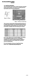
... with a good heat recovery characteristics. Lead Free Solder is strongly recommended to 370 degrees centigrade. KLV-26,32,32/H/S,37 S400A RM-GA011 1-5. Lead Free Information The circuit boards used in order to http://www.sony-training.com - 4 - This requires soldering equipment capable of Lead Free Solder, the soldering iron tip temperature needs...
... with a good heat recovery characteristics. Lead Free Solder is strongly recommended to 370 degrees centigrade. KLV-26,32,32/H/S,37 S400A RM-GA011 1-5. Lead Free Information The circuit boards used in order to http://www.sony-training.com - 4 - This requires soldering equipment capable of Lead Free Solder, the soldering iron tip temperature needs...
Revision History
Page 6
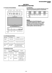
of Control Buttons MENU TV/VIDEO VOLUME CHANNEL POWER 2-4. STANDBY OFF Red lights Microcomputer is in a sleep state. KLV-26,32,32/H/S,37 S400A RM-GA011 SECTION 2 SELF DIAGNOSTIC FUNCTION 2-1. PICTURE OFF/ STANDBY POWER TIMER REMOTE/LIGHT SENSOR 2-2. Failure Classify the trouble causes by DC_ALERT 2. Overview of ...
of Control Buttons MENU TV/VIDEO VOLUME CHANNEL POWER 2-4. STANDBY OFF Red lights Microcomputer is in a sleep state. KLV-26,32,32/H/S,37 S400A RM-GA011 SECTION 2 SELF DIAGNOSTIC FUNCTION 2-1. PICTURE OFF/ STANDBY POWER TIMER REMOTE/LIGHT SENSOR 2-2. Failure Classify the trouble causes by DC_ALERT 2. Overview of ...
Revision History
Page 7
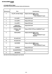
... times Error Countermeasure 2 DC_DET (12V Main Voltage) Replace either /both z BG1 board z GP(26",32")/ Power Unit(G2D)(37") board 3 DC_ALERT 1 Replace BG1 board. 4 DC_ALERT 2 Replace BG1 board. 5 DC_ALERT 3 Replace BG1 board. 6 BACKLIGHT/ Replace BG1 board. KLV-26,32,32/H/S,37 S400A RM-GA011 2-5. INVERTER ERROR 7... Speaker 9 Not used for GA - 10 Not used for GA - 11 NVM ERROR Replace either /both z BG1 board z GP(26",32")/ Power Unit(G2D)(37") board 12 IIC ERROR Replace BG1 board. 13 BALANCER ERROR Replace BG1 board. 14 HDMI ERROR - Note: Each ...
... times Error Countermeasure 2 DC_DET (12V Main Voltage) Replace either /both z BG1 board z GP(26",32")/ Power Unit(G2D)(37") board 3 DC_ALERT 1 Replace BG1 board. 4 DC_ALERT 2 Replace BG1 board. 5 DC_ALERT 3 Replace BG1 board. 6 BACKLIGHT/ Replace BG1 board. KLV-26,32,32/H/S,37 S400A RM-GA011 2-5. INVERTER ERROR 7... Speaker 9 Not used for GA - 10 Not used for GA - 11 NVM ERROR Replace either /both z BG1 board z GP(26",32")/ Power Unit(G2D)(37") board 12 IIC ERROR Replace BG1 board. 13 BALANCER ERROR Replace BG1 board. 14 HDMI ERROR - Note: Each ...
Revision History
Page 8
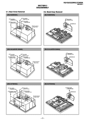
...) 4 Two screws (+PSW M3 X 5) 1 Sixteen screws (BVTP2 4 X 16) 2 Two screws (+BVTP 3 X 12) 3 One screw (+PSW M5 X 8) 5 Lift to remove Rear Cover (KLV-32,32/H/S S400A) 1 Three screws (+PSW M5 X 16) 2 Stand assy (KLV-37S400A) 4 Two screws (+PSW M3 X 5) 1 Seventeen screws (+BVTP2 4 X 16) 3 Two screws (+BVTP 3 X 12) 2 Four screws (+PSW ...
...) 4 Two screws (+PSW M3 X 5) 1 Sixteen screws (BVTP2 4 X 16) 2 Two screws (+BVTP 3 X 12) 3 One screw (+PSW M5 X 8) 5 Lift to remove Rear Cover (KLV-32,32/H/S S400A) 1 Three screws (+PSW M5 X 16) 2 Stand assy (KLV-37S400A) 4 Two screws (+PSW M3 X 5) 1 Seventeen screws (+BVTP2 4 X 16) 3 Two screws (+BVTP 3 X 12) 2 Four screws (+PSW ...
Revision History
Page 9
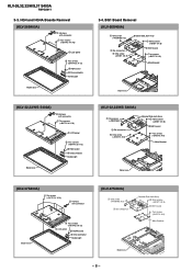
... Six screws (+BVTP2 4 X 16) 2 Harness with connector 1 Two screws (+BVTP2 4 X 16) 3 LCD panel 5 Two screws (+BVTP2 3 X 12) 6 HG4 board 4 One connector Guide Light Bezel assy 3-4. KLV-26,32,32/H/S,37 S400A RM-GA011 3-3. HG4 and HG4A Boards Removal (KLV-26S400A) 2 Harness with connector 1 Two screws ...(+BVTP2 4 X 16) 3 LCD panel 5 Two screws (+BVTP2 3 X 12) 6 HG4 board 4 One connector Guide Light Bezel assy (KLV-32,32/H/S S400A) 2 Harness with connector Bezel assy 5 Two screws (+BVTP2 3 X 12) 3 LCD panel 6 HG4A board 4 One connector Guide Light (KLV-37S400A...
... Six screws (+BVTP2 4 X 16) 2 Harness with connector 1 Two screws (+BVTP2 4 X 16) 3 LCD panel 5 Two screws (+BVTP2 3 X 12) 6 HG4 board 4 One connector Guide Light Bezel assy 3-4. KLV-26,32,32/H/S,37 S400A RM-GA011 3-3. HG4 and HG4A Boards Removal (KLV-26S400A) 2 Harness with connector 1 Two screws ...(+BVTP2 4 X 16) 3 LCD panel 5 Two screws (+BVTP2 3 X 12) 6 HG4 board 4 One connector Guide Light Bezel assy (KLV-32,32/H/S S400A) 2 Harness with connector Bezel assy 5 Two screws (+BVTP2 3 X 12) 3 LCD panel 6 HG4A board 4 One connector Guide Light (KLV-37S400A...
Revision History
Page 10
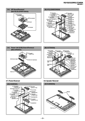
... screw (+PSW M4 X 8) Frame Spine (R) 6 Two screws (+BVTP2 4 X 16) Frame Bottom 3-8. 3-5. GP Board Removal (KLV-26,32,32/H/S S400A) 1 Four screws (+PSW 3SG) 2 One connector 3 GP board G1 Bracket KLV-26,32,32/H/S,37 S400A RM-GA011 (KLV-32,32/H/S S400A) 4 One screw (+PSW M4 X 8) 5 One screw (+PSW M4 X 8) 2 Two screws (+PSW M4 X 8) Vesa Frame (Top...
... screw (+PSW M4 X 8) Frame Spine (R) 6 Two screws (+BVTP2 4 X 16) Frame Bottom 3-8. 3-5. GP Board Removal (KLV-26,32,32/H/S S400A) 1 Four screws (+PSW 3SG) 2 One connector 3 GP board G1 Bracket KLV-26,32,32/H/S,37 S400A RM-GA011 (KLV-32,32/H/S S400A) 4 One screw (+PSW M4 X 8) 5 One screw (+PSW M4 X 8) 2 Two screws (+PSW M4 X 8) Vesa Frame (Top...
Revision History
Page 11
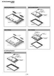
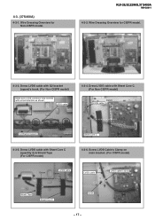
KLV-26,32,32/H/S,37 S400A RM-GA011 (KLV-32,32/H/S S400A) Speaker (KLV-32,32/H/S S400A) 2 Harness with connector 1 Two screws (+BVTP2 4 X 16) 3 Lift to remove LCD panel Bezel assy (KLV-37S400A) Speaker Bezel assy (KLV-37S400A) 2 Six screws (+BVTP2 4 X 16) 1 Harness with connector 1 Two screws (+BVTP2 4 X 16) 3 Lift to remove LCD panel Bezel assy 3-9. LCD Panel Removal (KLV-26S400A) 2 Harness with connector 3 Lift to remove LCD panel Bezel assy Bezel assy - 10 -
KLV-26,32,32/H/S,37 S400A RM-GA011 (KLV-32,32/H/S S400A) Speaker (KLV-32,32/H/S S400A) 2 Harness with connector 1 Two screws (+BVTP2 4 X 16) 3 Lift to remove LCD panel Bezel assy (KLV-37S400A) Speaker Bezel assy (KLV-37S400A) 2 Six screws (+BVTP2 4 X 16) 1 Harness with connector 1 Two screws (+BVTP2 4 X 16) 3 Lift to remove LCD panel Bezel assy 3-9. LCD Panel Removal (KLV-26S400A) 2 Harness with connector 3 Lift to remove LCD panel Bezel assy Bezel assy - 10 -
Revision History
Page 12
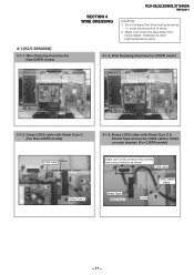
... sure LVDS connector fully inserted with Sheet Core C. (For Non-CISPR model) LVDS cable Datum Datum Sheet Core C 4-1-4. 4-1.(KLV-26S400A) 4-1-1. SECTION 4 WIRE DRESSING KLV-26,32,32/H/S,37 S400A RM-GA011 CAUTION : 1. LVDS cable Shield Tape Sheet Core C LVDS cable's clamp Screw - 11 -
... sure LVDS connector fully inserted with Sheet Core C. (For Non-CISPR model) LVDS cable Datum Datum Sheet Core C 4-1-4. 4-1.(KLV-26S400A) 4-1-1. SECTION 4 WIRE DRESSING KLV-26,32,32/H/S,37 S400A RM-GA011 CAUTION : 1. LVDS cable Shield Tape Sheet Core C LVDS cable's clamp Screw - 11 -
Revision History
Page 13
...+20P Pull wire straight Connector assy 13P 4-1-9. Dress Connector Assy 14P+20P at G1 bracket's hook, Connector assy 13P 4-1-6. Dress Connector Assy 14P+20P on LCD panel and dress Connector Assy 14P+20P & Speaker Wire with Slide Clamp (quantity: 2) Connector assy 14P+20P 4-1-8. Connector assy 14P+20P Sheet Core C Datum Caution... Core C (quantity: 2). 4-1-10. Datum Sheet Core C Datum Speaker Wire Daattuumm Connector assy 14P+20P Caution : Pull away from screw boss Screw boss - 12 - KLV-26,32,32/H/S,37 S400A RM-GA011 4-1-5. Dress Connector Assy 13P at G1 bracket's hook.
...+20P Pull wire straight Connector assy 13P 4-1-9. Dress Connector Assy 14P+20P at G1 bracket's hook, Connector assy 13P 4-1-6. Dress Connector Assy 14P+20P on LCD panel and dress Connector Assy 14P+20P & Speaker Wire with Slide Clamp (quantity: 2) Connector assy 14P+20P 4-1-8. Connector assy 14P+20P Sheet Core C Datum Caution... Core C (quantity: 2). 4-1-10. Datum Sheet Core C Datum Speaker Wire Daattuumm Connector assy 14P+20P Caution : Pull away from screw boss Screw boss - 12 - KLV-26,32,32/H/S,37 S400A RM-GA011 4-1-5. Dress Connector Assy 13P at G1 bracket's hook.
Revision History
Page 14
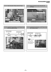
Install AC Cord Holder on AC Power Cord. (For Non-CISPR model) 4-1-14. LCD tape Datum Speaker Wire Screw boss Caution : Pull away from screw boss Connector assy 14P+20P Datum LCD tape 4-1-13. Dress Connector Assy 14P+20P with LCD tape. Install AC Cord Holder on AC Power Cord. (For CISPR model) AC Cord holder AC Power Cord 130mm AC Cord holder AC Power Cord 70mm 130mm Ferrite Core Cable tie Note: Make sure tighten cable tie and cut excess part. - 13 - KLV-26,32,32/H/S,37 S400A RM-GA011 4-1-12. 4-1-11. Dress Speaker Wire(L) with LCD tape.
Install AC Cord Holder on AC Power Cord. (For Non-CISPR model) 4-1-14. LCD tape Datum Speaker Wire Screw boss Caution : Pull away from screw boss Connector assy 14P+20P Datum LCD tape 4-1-13. Dress Connector Assy 14P+20P with LCD tape. Install AC Cord Holder on AC Power Cord. (For CISPR model) AC Cord holder AC Power Cord 130mm AC Cord holder AC Power Cord 70mm 130mm Ferrite Core Cable tie Note: Make sure tighten cable tie and cut excess part. - 13 - KLV-26,32,32/H/S,37 S400A RM-GA011 4-1-12. 4-1-11. Dress Speaker Wire(L) with LCD tape.
Revision History
Page 15
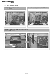
Wire Dressing Overview for Non-CISPR model 4-2-2. LVDS cable Datum Datum UUsseeUULLtatpaepe location as shown. Wire Dressing Overview for CISPR model 4-2-3. Dress LVDS Cable with Sheet Core C (quantity: 2). (For Non-CISPR model) Make sure LVDS connector fully inserted with correct direction as guide line UL Tape Sheet Core C Datum - 14 - KLV-26,32,32/H/S,37 S400A RM-GA011 4-2. (KLV-32,32/H/S S400A) 4-2-1.
Wire Dressing Overview for Non-CISPR model 4-2-2. LVDS cable Datum Datum UUsseeUULLtatpaepe location as shown. Wire Dressing Overview for CISPR model 4-2-3. Dress LVDS Cable with Sheet Core C (quantity: 2). (For Non-CISPR model) Make sure LVDS connector fully inserted with correct direction as guide line UL Tape Sheet Core C Datum - 14 - KLV-26,32,32/H/S,37 S400A RM-GA011 4-2. (KLV-32,32/H/S S400A) 4-2-1.
Revision History
Page 16
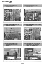
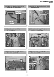
... 13P Screw 4-2-7. Dress Connector Assy 13P at Bracket's hook (quantity: 5). Dress Connector Assy 14P + 20P with Sheet Core C & Shield Tape. (For CISPR model) KLV-26,32,32/H/S,37 S400A RM-GA011 4-2-5. Screw LVDS cable's clamp on top of this area. Dress Connector Assy 14P+20P on main bracket. (For CISPR model) Apply...
... 13P Screw 4-2-7. Dress Connector Assy 13P at Bracket's hook (quantity: 5). Dress Connector Assy 14P + 20P with Sheet Core C & Shield Tape. (For CISPR model) KLV-26,32,32/H/S,37 S400A RM-GA011 4-2-5. Screw LVDS cable's clamp on top of this area. Dress Connector Assy 14P+20P on main bracket. (For CISPR model) Apply...
Revision History
Page 17
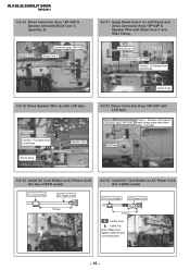
... 14P+20P with Sheet Core C and Slide Clamp. Caution : Pull wire until cannot Connector assy 14P+20P reach sharp edge area when apply LCD tape. Datum LCD tape 4-2-14. LCD tape Datum Caution : Pull away from screw boss Screw boss 4-2-12. Install AC Cord Holder on AC Power Cord. (For Non-CISPR model...) AC Cord holder AC Power Cord 70mm 170mm Ferrite Core Cable Tie Note: Make sure tighten cable tie and cut excess part. - 16 - KLV-26,32,32/H/S,37 S400A RM-GA011 4-2-10.
... 14P+20P with Sheet Core C and Slide Clamp. Caution : Pull wire until cannot Connector assy 14P+20P reach sharp edge area when apply LCD tape. Datum LCD tape 4-2-14. LCD tape Datum Caution : Pull away from screw boss Screw boss 4-2-12. Install AC Cord Holder on AC Power Cord. (For Non-CISPR model...) AC Cord holder AC Power Cord 70mm 170mm Ferrite Core Cable Tie Note: Make sure tighten cable tie and cut excess part. - 16 - KLV-26,32,32/H/S,37 S400A RM-GA011 4-2-10.
Revision History
Page 18
... Core C. (For Non-CISPR model) Datum LVDS cable Datum G2 Bracket (upper) Sheet Core C 4-3-5. Dress LVDS cable with correct direction as shown. 4-3. (37S400A) 4-3-1. KLV-26,32,32/H/S,37 S400A RM-GA011 4-3-2. Dress LVDS cable with Sheet Core C (quantity 2) & Shield Tape (For CISPR model) 4-3-6. LVDS cable 4-3-4. Wire Dressing Overview for CISPR model. 4-3-3. Screw...
... Core C. (For Non-CISPR model) Datum LVDS cable Datum G2 Bracket (upper) Sheet Core C 4-3-5. Dress LVDS cable with correct direction as shown. 4-3. (37S400A) 4-3-1. KLV-26,32,32/H/S,37 S400A RM-GA011 4-3-2. Dress LVDS cable with Sheet Core C (quantity 2) & Shield Tape (For CISPR model) 4-3-6. LVDS cable 4-3-4. Wire Dressing Overview for CISPR model. 4-3-3. Screw...
Revision History
Page 19
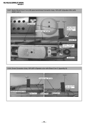
Datum Connector assy 14P+20P Datum Dress wire along panel edge Sheet Core C Speaker Wire Sheet Core C Dress wire along panel edge - 18 - Apply Sheet Core C on LCD panel and dress Connector Assy 14P+20P & Speaker Wire with Sheet Core C (quantity:2). Dress Connector Assy 14P+20P & Speaker wire with sheet core C. KLV-26,32,32/H/S,37 S400A RM-GA011 4-3-7. Sheet Core C Connector assy 14P+20P Datum Datum Datum Follow White UL tape as guide to apply tape Speaker Wire Caution : Pull away from screw boss Screw boss 4-3-8.
Datum Connector assy 14P+20P Datum Dress wire along panel edge Sheet Core C Speaker Wire Sheet Core C Dress wire along panel edge - 18 - Apply Sheet Core C on LCD panel and dress Connector Assy 14P+20P & Speaker Wire with Sheet Core C (quantity:2). Dress Connector Assy 14P+20P & Speaker wire with sheet core C. KLV-26,32,32/H/S,37 S400A RM-GA011 4-3-7. Sheet Core C Connector assy 14P+20P Datum Datum Datum Follow White UL tape as guide to apply tape Speaker Wire Caution : Pull away from screw boss Screw boss 4-3-8.
Revision History
Page 20
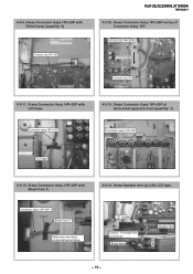
... Assy 14P+20P at G2 bracket (upper)'s hook (quantity: 7) Connector assy 14P+20P Datum LCD tape Connector assy 14P+20P 4-3-13. Dress Speaker wire (L) with Slide Clamp (quantity: 2) Connector assy 14P+20P KLV-26,32,32/H/S,37 S400A RM-GA011 4-3-10. Dress Connector Assy 14P+20P with... LCD tape. Dress Connector Assy 14P+20P with LCD tape. 4-3-12. Connector assy 14P+20P Datum Sheet Core C Make sure wire dress underneath...
... Assy 14P+20P at G2 bracket (upper)'s hook (quantity: 7) Connector assy 14P+20P Datum LCD tape Connector assy 14P+20P 4-3-13. Dress Speaker wire (L) with Slide Clamp (quantity: 2) Connector assy 14P+20P KLV-26,32,32/H/S,37 S400A RM-GA011 4-3-10. Dress Connector Assy 14P+20P with... LCD tape. Dress Connector Assy 14P+20P with LCD tape. 4-3-12. Connector assy 14P+20P Datum Sheet Core C Make sure wire dress underneath...
Revision History
Page 21
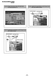
Dress Connector Assy 14P+20P with LCD tape (quantity: 2) Connector assy 14P+20P Datum 4-3-16. Install AC Cord Holder on AC Power Cord (For Non-CISPR model) AC Cord holder AC Power Cord 130mm LCD tape Datum 4-3-17. KLV-26,32,32/H/S,37 S400A RM-GA011 4-3-15. Install AC Cord Holder on AC Power Cord. (For CISPR model) AC Cord holder AC Power Cord 70mm 130mm Ferrite Core Cable tie Note: Make sure tighten cable tie and cut excess part. - 20 -
Dress Connector Assy 14P+20P with LCD tape (quantity: 2) Connector assy 14P+20P Datum 4-3-16. Install AC Cord Holder on AC Power Cord (For Non-CISPR model) AC Cord holder AC Power Cord 130mm LCD tape Datum 4-3-17. KLV-26,32,32/H/S,37 S400A RM-GA011 4-3-15. Install AC Cord Holder on AC Power Cord. (For CISPR model) AC Cord holder AC Power Cord 70mm 130mm Ferrite Core Cable tie Note: Make sure tighten cable tie and cut excess part. - 20 -
Revision History
Page 22
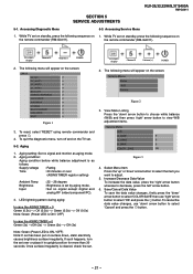
... and on the screen: Service Menu Status W/B Service Figure 2 3. SECTION 5 SERVICE ADJUSTMENTS KLV-26,32,32/H/S,37 S400A RM-GA011 5-1. Accessing Diagnostic Menu 5-3. Aging setting: Set no signal except digital and analog ...press the 'down , static electricity causes brightness surface irregularity. The following menu will appear on the TV set . - 21 - To cancel the data value changes, use 'right' arrow button to select...: Set no signal and monitor as follows: Supply voltage : Rating Time : 20 minutes or over or place it in upright position for more than 30 seconds...
... and on the screen: Service Menu Status W/B Service Figure 2 3. SECTION 5 SERVICE ADJUSTMENTS KLV-26,32,32/H/S,37 S400A RM-GA011 5-1. Accessing Diagnostic Menu 5-3. Aging setting: Set no signal except digital and analog ...press the 'down , static electricity causes brightness surface irregularity. The following menu will appear on the TV set . - 21 - To cancel the data value changes, use 'right' arrow button to select...: Set no signal and monitor as follows: Supply voltage : Rating Time : 20 minutes or over or place it in upright position for more than 30 seconds...

