Revision History
Page 3
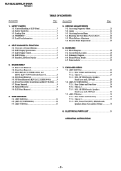
... 5-2. DIAGRAMS 6-1. Schematic Diagram 25 6-4. BG1 Board Removal 8 3-5. GP Board Removal (KLV-26,32,32/H/S S400A 9 3-6. Speaker Removal 9 3-9. BG1, GP, HG4 Boards, Speakers, Bezel Assy and LCD Panel 31 7-3. (KLV-37S400A 32 7-3-1. SAFETY NOTES 1-1. Aging 21 5-3. Standby LED Error Display 6 6. HG4 (KLV-26,32,32/H/S S400A) and HG4A (KLV-37S400A) Boards Removal 8 3-4. BG1, GP, HG4 Boards, Speakers...
... 5-2. DIAGRAMS 6-1. Schematic Diagram 25 6-4. BG1 Board Removal 8 3-5. GP Board Removal (KLV-26,32,32/H/S S400A 9 3-6. Speaker Removal 9 3-9. BG1, GP, HG4 Boards, Speakers, Bezel Assy and LCD Panel 31 7-3. (KLV-37S400A 32 7-3-1. SAFETY NOTES 1-1. Aging 21 5-3. Standby LED Error Display 6 6. HG4 (KLV-26,32,32/H/S S400A) and HG4A (KLV-37S400A) Boards Removal 8 3-4. BG1, GP, HG4 Boards, Speakers...
Revision History
Page 4
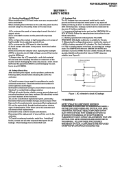
... the backlight (CCFL) or inverter circuit. (High voltage occurs at the inverter circuit at 650Vrms) 7) Always clean the LCD panel with a wrist band. The 'limit' indication is suitable for this job. 3. REPLACE THESE COMPONENTS WITH SONY PARTS WHOSE PART NUMBERS APPEAR AS SHOWN IN THIS ... FOR SAFE OPERATION ARE IDENTIFIED IN THIS MANUAL. KLV-26,32,32/H/S,37 S400A RM-GA011 SECTION 1 SAFETY NOTES 1-1. WARNING ! Caution Handling of LCD Panel When installing the LCD Panel, make sure you have an accurate low voltage scale. Leakage Test The AC leakage from any exposed metal...
... the backlight (CCFL) or inverter circuit. (High voltage occurs at the inverter circuit at 650Vrms) 7) Always clean the LCD panel with a wrist band. The 'limit' indication is suitable for this job. 3. REPLACE THESE COMPONENTS WITH SONY PARTS WHOSE PART NUMBERS APPEAR AS SHOWN IN THIS ... FOR SAFE OPERATION ARE IDENTIFIED IN THIS MANUAL. KLV-26,32,32/H/S,37 S400A RM-GA011 SECTION 1 SAFETY NOTES 1-1. WARNING ! Caution Handling of LCD Panel When installing the LCD Panel, make sure you have an accurate low voltage scale. Leakage Test The AC leakage from any exposed metal...
Revision History
Page 9
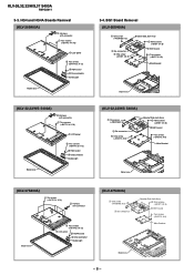
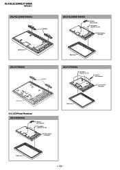
... connectors 5 One screw (+BVST 3 X 8) Bracket Side Jack Assy 2 Nine screws (+BVST 3 X 8) 4 BG1 board Two screws (+BVST 3 X 8) Main Bracket Bezel assy (KLV-32,32/H/S S400A) 1 One screw (+PSW M3 X 5) 3 Six connectors 5 One screw (+BVST 3 X 8) Bracket Side Jack Assy 2 Nine screws (+BVST 3 X 8) 4 BG1 board Two...with connector 1 Two screws (+BVTP2 4 X 16) 3 LCD panel 5 Two screws (+BVTP2 3 X 12) 6 HG4 board 4 One connector Guide Light Bezel assy (KLV-32,32/H/S S400A) 2 Harness with connector Bezel assy 5 Two screws (+BVTP2 3 X 12) 3 LCD panel 6 HG4A board 4 One connector Guide Light (KLV-...
... connectors 5 One screw (+BVST 3 X 8) Bracket Side Jack Assy 2 Nine screws (+BVST 3 X 8) 4 BG1 board Two screws (+BVST 3 X 8) Main Bracket Bezel assy (KLV-32,32/H/S S400A) 1 One screw (+PSW M3 X 5) 3 Six connectors 5 One screw (+BVST 3 X 8) Bracket Side Jack Assy 2 Nine screws (+BVST 3 X 8) 4 BG1 board Two...with connector 1 Two screws (+BVTP2 4 X 16) 3 LCD panel 5 Two screws (+BVTP2 3 X 12) 6 HG4 board 4 One connector Guide Light Bezel assy (KLV-32,32/H/S S400A) 2 Harness with connector Bezel assy 5 Two screws (+BVTP2 3 X 12) 3 LCD panel 6 HG4A board 4 One connector Guide Light (KLV-...
Revision History
Page 11
KLV-26,32,32/H/S,37 S400A RM-GA011 (KLV-32,32/H/S S400A) Speaker (KLV-32,32/H/S S400A) 2 Harness with connector 1 Two screws (+BVTP2 4 X 16) 3 Lift to remove LCD panel Bezel assy (KLV-37S400A) Speaker Bezel assy (KLV-37S400A) 2 Six screws (+BVTP2 4 X 16) 1 Harness with connector 1 Two screws (+BVTP2 4 X 16) 3 Lift to remove LCD panel Bezel assy 3-9. LCD Panel Removal (KLV-26S400A) 2 Harness with connector 3 Lift to remove LCD panel Bezel assy Bezel assy - 10 -
KLV-26,32,32/H/S,37 S400A RM-GA011 (KLV-32,32/H/S S400A) Speaker (KLV-32,32/H/S S400A) 2 Harness with connector 1 Two screws (+BVTP2 4 X 16) 3 Lift to remove LCD panel Bezel assy (KLV-37S400A) Speaker Bezel assy (KLV-37S400A) 2 Six screws (+BVTP2 4 X 16) 1 Harness with connector 1 Two screws (+BVTP2 4 X 16) 3 Lift to remove LCD panel Bezel assy 3-9. LCD Panel Removal (KLV-26S400A) 2 Harness with connector 3 Lift to remove LCD panel Bezel assy Bezel assy - 10 -
Revision History
Page 13
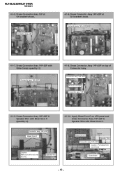
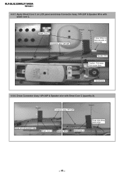
KLV-26,32,32/H/S,37 S400A RM-GA011 4-1-5. Connector assy 14P+20P 4-1-7. Dress Connector Assy 14P+20P on LCD panel and dress Connector Assy 14P+20P & Speaker Wire with Sheet Core C. Dress Connector Assy 14P+20P & Speaker Wire with Slide Clamp (quantity: 2) Connector assy ...
KLV-26,32,32/H/S,37 S400A RM-GA011 4-1-5. Connector assy 14P+20P 4-1-7. Dress Connector Assy 14P+20P on LCD panel and dress Connector Assy 14P+20P & Speaker Wire with Sheet Core C. Dress Connector Assy 14P+20P & Speaker Wire with Slide Clamp (quantity: 2) Connector assy ...
Revision History
Page 14
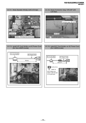
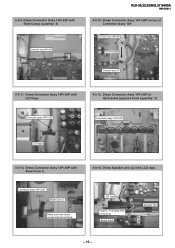
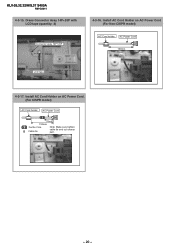
Dress Speaker Wire(L) with LCD tape. Dress Connector Assy 14P+20P with LCD tape. Install AC Cord Holder on AC Power Cord. (For CISPR model) AC Cord holder AC Power Cord 130mm AC Cord holder AC Power Cord 70mm 130mm Ferrite Core Cable tie Note: Make sure tighten cable tie and cut excess part. - 13 - KLV-26,32,32/H/S,37 S400A RM-GA011 4-1-12. LCD tape Datum Speaker Wire Screw boss Caution : Pull away from screw boss Connector assy 14P+20P Datum LCD tape 4-1-13. Install AC Cord Holder on AC Power Cord. (For Non-CISPR model) 4-1-14. 4-1-11.
Dress Speaker Wire(L) with LCD tape. Dress Connector Assy 14P+20P with LCD tape. Install AC Cord Holder on AC Power Cord. (For CISPR model) AC Cord holder AC Power Cord 130mm AC Cord holder AC Power Cord 70mm 130mm Ferrite Core Cable tie Note: Make sure tighten cable tie and cut excess part. - 13 - KLV-26,32,32/H/S,37 S400A RM-GA011 4-1-12. LCD tape Datum Speaker Wire Screw boss Caution : Pull away from screw boss Connector assy 14P+20P Datum LCD tape 4-1-13. Install AC Cord Holder on AC Power Cord. (For Non-CISPR model) 4-1-14. 4-1-11.
Revision History
Page 17
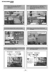
...on AC Power Cord. (For Non-CISPR model) AC Cord holder AC Power Cord 170mm 4-2-15. Dress Connector Assy 14P+20P & Speaker wire with LCD tape. Dress Connector Assy 14P+20P with Sheet Core C (quantity: 2) Speaker Wire Connector assy 14P+20P Sheet Core C Datum Datum 4-2-11. KLV-26...,32,32/H/S,37 S400A RM-GA011 4-2-10. Sheet Core C Speaker Wire Datum Connector assy 14P+20P Caution : Pull away from screw boss Speaker Wire Screw boss 4-2-...
...on AC Power Cord. (For Non-CISPR model) AC Cord holder AC Power Cord 170mm 4-2-15. Dress Connector Assy 14P+20P & Speaker wire with LCD tape. Dress Connector Assy 14P+20P with Sheet Core C (quantity: 2) Speaker Wire Connector assy 14P+20P Sheet Core C Datum Datum 4-2-11. KLV-26...,32,32/H/S,37 S400A RM-GA011 4-2-10. Sheet Core C Speaker Wire Datum Connector assy 14P+20P Caution : Pull away from screw boss Speaker Wire Screw boss 4-2-...
Revision History
Page 19
Sheet Core C Connector assy 14P+20P Datum Datum Datum Follow White UL tape as guide to apply tape Speaker Wire Caution : Pull away from screw boss Screw boss 4-3-8. KLV-26,32,32/H/S,37 S400A RM-GA011 4-3-7. Datum Connector assy 14P+20P Datum Dress wire along panel edge Sheet Core C Speaker Wire Sheet Core C Dress wire along panel edge - 18 - Dress Connector Assy 14P+20P & Speaker wire with sheet core C. Apply Sheet Core C on LCD panel and dress Connector Assy 14P+20P & Speaker Wire with Sheet Core C (quantity:2).
Sheet Core C Connector assy 14P+20P Datum Datum Datum Follow White UL tape as guide to apply tape Speaker Wire Caution : Pull away from screw boss Screw boss 4-3-8. KLV-26,32,32/H/S,37 S400A RM-GA011 4-3-7. Datum Connector assy 14P+20P Datum Dress wire along panel edge Sheet Core C Speaker Wire Sheet Core C Dress wire along panel edge - 18 - Dress Connector Assy 14P+20P & Speaker wire with sheet core C. Apply Sheet Core C on LCD panel and dress Connector Assy 14P+20P & Speaker Wire with Sheet Core C (quantity:2).
Revision History
Page 20
...Connector Assy 14P+20P on top of Connector Assy 13P. Dress Connector Assy 14P+20P with LCD tape. Dress Connector Assy 14P+20P with Slide Clamp (quantity: 2) Connector assy 14P+20P KLV-26,32,32/H/S,37 S400A RM-GA011 4-3-10. Connector assy 14P+20P Pull wire straight Connector assy 13P ...4-3-11. Connector assy 14P+20P Datum Sheet Core C Make sure wire dress underneath spine frame LCD tape Datum Caution : Pull away from screw boss...
...Connector Assy 14P+20P on top of Connector Assy 13P. Dress Connector Assy 14P+20P with LCD tape. Dress Connector Assy 14P+20P with Slide Clamp (quantity: 2) Connector assy 14P+20P KLV-26,32,32/H/S,37 S400A RM-GA011 4-3-10. Connector assy 14P+20P Pull wire straight Connector assy 13P ...4-3-11. Connector assy 14P+20P Datum Sheet Core C Make sure wire dress underneath spine frame LCD tape Datum Caution : Pull away from screw boss...
Revision History
Page 21
Install AC Cord Holder on AC Power Cord. (For CISPR model) AC Cord holder AC Power Cord 70mm 130mm Ferrite Core Cable tie Note: Make sure tighten cable tie and cut excess part. - 20 - KLV-26,32,32/H/S,37 S400A RM-GA011 4-3-15. Install AC Cord Holder on AC Power Cord (For Non-CISPR model) AC Cord holder AC Power Cord 130mm LCD tape Datum 4-3-17. Dress Connector Assy 14P+20P with LCD tape (quantity: 2) Connector assy 14P+20P Datum 4-3-16.
Install AC Cord Holder on AC Power Cord. (For CISPR model) AC Cord holder AC Power Cord 70mm 130mm Ferrite Core Cable tie Note: Make sure tighten cable tie and cut excess part. - 20 - KLV-26,32,32/H/S,37 S400A RM-GA011 4-3-15. Install AC Cord Holder on AC Power Cord (For Non-CISPR model) AC Cord holder AC Power Cord 130mm LCD tape Datum 4-3-17. Dress Connector Assy 14P+20P with LCD tape (quantity: 2) Connector assy 14P+20P Datum 4-3-16.
Revision History
Page 29
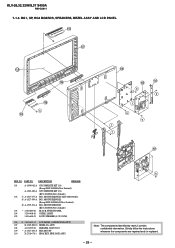
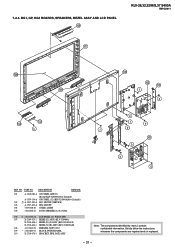
KLV-26,32,32/H/S,37 S400A RM-GA011 7-1-3. PART NO. BG1, GP, HG4 BOARDS, SPEAKERS, BEZEL ASSY AND LCD PANEL 103 107 108 105 109 k 104 106 102 110 b a f e e f f 101 REF. DESCRIPTION REMARK 101 A-1540-082-A GP COMPLETE KIT (26) (Except KLV-26S400A(New ... 104 3-290-408-01 GUIDE, LIGHT 105 1-826-648-21 LOUD SPEAKER (4.2 X 15CM) 106 ! 1-802-613-11 LCD PANEL (26INCH WXGA TFT) 107 X-2189-890-01 BEZEL(26) ASSY 108 4-103-599-21 EMBLEM, SONY NO.7 109 * A-1527-469-A HG4 MOUNT 110 X-2318-678-1 BRACKET, SIDE JACK ASSY h Note: The components identified...
KLV-26,32,32/H/S,37 S400A RM-GA011 7-1-3. PART NO. BG1, GP, HG4 BOARDS, SPEAKERS, BEZEL ASSY AND LCD PANEL 103 107 108 105 109 k 104 106 102 110 b a f e e f f 101 REF. DESCRIPTION REMARK 101 A-1540-082-A GP COMPLETE KIT (26) (Except KLV-26S400A(New ... 104 3-290-408-01 GUIDE, LIGHT 105 1-826-648-21 LOUD SPEAKER (4.2 X 15CM) 106 ! 1-802-613-11 LCD PANEL (26INCH WXGA TFT) 107 X-2189-890-01 BEZEL(26) ASSY 108 4-103-599-21 EMBLEM, SONY NO.7 109 * A-1527-469-A HG4 MOUNT 110 X-2318-678-1 BRACKET, SIDE JACK ASSY h Note: The components identified...
Revision History
Page 32
... 105 1-826-648-21 LOUD SPEAKER (4.2 X 15CM) 106 ! 1-802-653-12 LCD PANEL (32 WXGA TFT) 107 X-2189-523-1 BEZEL(32) ASSY (KLV-32S400A) X-2318-468-1 BEZEL(32)(S) ASSY (KLV-32S400A/S) X-2318-464-1 BEZEL(32)(H) ASSY (KLV-32S400A/H) 108 4-103-642-21 EMBLEM, SONY NO.7 109 * 1-480-889-11 BLOCK SWITCH PANEL 110 X-2318-678-1 BRACKET...
... 105 1-826-648-21 LOUD SPEAKER (4.2 X 15CM) 106 ! 1-802-653-12 LCD PANEL (32 WXGA TFT) 107 X-2189-523-1 BEZEL(32) ASSY (KLV-32S400A) X-2318-468-1 BEZEL(32)(S) ASSY (KLV-32S400A/S) X-2318-464-1 BEZEL(32)(H) ASSY (KLV-32S400A/H) 108 4-103-642-21 EMBLEM, SONY NO.7 109 * 1-480-889-11 BLOCK SWITCH PANEL 110 X-2318-678-1 BRACKET...
Revision History
Page 35
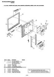
...-408-01 GUIDE, LIGHT 104 1-826-648-21 LOUD SPEAKER (4.2 X 15CM) 105 ! 1-802-622-11 LCD PANEL (37INCH WXGA TFT) 106 X-2190-008-1 BEZEL(37) ASSY 107 4-103-642-21 EMBLEM, SONY NO.7 108 * 1-480-889-11 BLOCK SWITCH PANEL 109 * X-2318-678-1 BRACKET, SIDE JACK ASSY 110... The components identified by mark contain confidential information. NO. KLV-26,32,32/H/S,37 S400A RM-GA011 7-3-3. Strictly follow the instructions whenever the components are repaired and /or replaced. - 34 - BG1, POWER UNIT (G2D), HG4A BOARDS, SPEAKERS, BEZEL ASSY AND LCD PANEL 108 106 107 104 105 101 f 109 a 102 103 ...
...-408-01 GUIDE, LIGHT 104 1-826-648-21 LOUD SPEAKER (4.2 X 15CM) 105 ! 1-802-622-11 LCD PANEL (37INCH WXGA TFT) 106 X-2190-008-1 BEZEL(37) ASSY 107 4-103-642-21 EMBLEM, SONY NO.7 108 * 1-480-889-11 BLOCK SWITCH PANEL 109 * X-2318-678-1 BRACKET, SIDE JACK ASSY 110... The components identified by mark contain confidential information. NO. KLV-26,32,32/H/S,37 S400A RM-GA011 7-3-3. Strictly follow the instructions whenever the components are repaired and /or replaced. - 34 - BG1, POWER UNIT (G2D), HG4A BOARDS, SPEAKERS, BEZEL ASSY AND LCD PANEL 108 106 107 104 105 101 f 109 a 102 103 ...
Revision History
Page 38
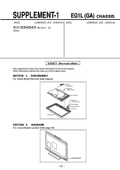
HG4A Board Removal (refer page 8) 2 Harness with connector 1 Two screws (+BVTP2 4 X 16) 3 LCD panel 5 Two screws (+BVTP2 3 X 12) 6 HG4A board 4 One connector Guide Light Bezel assy SECTION 6. SUPPLEMENT-1 EG1L (GA) CHASSIS MODEL COMMANDER DEST. CHASSIS NO. SUBJECT : New ...
HG4A Board Removal (refer page 8) 2 Harness with connector 1 Two screws (+BVTP2 4 X 16) 3 LCD panel 5 Two screws (+BVTP2 3 X 12) 6 HG4A board 4 One connector Guide Light Bezel assy SECTION 6. SUPPLEMENT-1 EG1L (GA) CHASSIS MODEL COMMANDER DEST. CHASSIS NO. SUBJECT : New ...
Revision History
Page 40
KLV-40S400A KLV-37S400A KLV-32S400A KLV-26S400A © 2008 Sony Corporation LCD Colour TV Operating Instructions 3-293-038-11(1) 3-293-038-11(1)
KLV-40S400A KLV-37S400A KLV-32S400A KLV-26S400A © 2008 Sony Corporation LCD Colour TV Operating Instructions 3-293-038-11(1) 3-293-038-11(1)
Revision History
Page 48
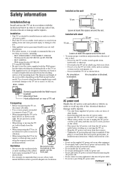
... you use the screws supplied with the Wall-mount bracket when attaching the mounting hooks to use a Sony wall- KLV-26S400A: Wall-mount bracket SU-WL100 TV stand SU-FL300M • Be sure to the TV set with dust and it regularly. The supplied screws are designed so that they are needed to... put stress on a shelf, rug, bed or in a closet. - The diameter and length of the panel, not the front part. Do not place the TV set on the LCD panel. • When lifting or moving , pack it from falling down , backwards, or sideways. - Wall Wall AC power cord Handle the AC power...
... you use the screws supplied with the Wall-mount bracket when attaching the mounting hooks to use a Sony wall- KLV-26S400A: Wall-mount bracket SU-WL100 TV stand SU-FL300M • Be sure to the TV set with dust and it regularly. The supplied screws are designed so that they are needed to... put stress on a shelf, rug, bed or in a closet. - The diameter and length of the panel, not the front part. Do not place the TV set on the LCD panel. • When lifting or moving , pack it from falling down , backwards, or sideways. - Wall Wall AC power cord Handle the AC power...
Revision History
Page 49
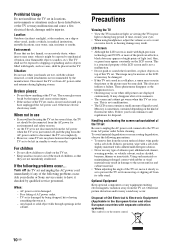
... volatile solvent, such as the temperature rises. • Ghosting may enter; If dust is on the TV. LCD Screen • Although the LCD screen is made with separate collection systems) This symbol is persistent, wipe with a soft cloth slightly moistened with liquids, such as those listed below... thrown at the TV set . Optional Equipment Keep optional components or any of the TV set, move it might be damaged. • If this TV set to mechanical vibration, near water, rain, moisture or smoke. Disposal of time, strains your dealer or Sony service centre to ...
... volatile solvent, such as the temperature rises. • Ghosting may enter; If dust is on the TV. LCD Screen • Although the LCD screen is made with separate collection systems) This symbol is persistent, wipe with a soft cloth slightly moistened with liquids, such as those listed below... thrown at the TV set . Optional Equipment Keep optional components or any of the TV set, move it might be damaged. • If this TV set to mechanical vibration, near water, rain, moisture or smoke. Disposal of time, strains your dealer or Sony service centre to ...
Revision History
Page 71
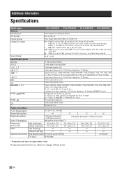
Additional Information Specifications Model name KLV-40S400A KLV-37S400A KLV-32S400A KLV-26S400A System Panel System LCD (Liquid Crystal Display) Panel TV System B/G, I, D/K, M Colour System PAL, PAL60, SECAM, NTSC4.43, NTSC3.58 Channel Coverage Sound Output B/G: VHF: E2 to E12/ UHF: E21 to E69/ CATV: S01 to S03, S1 to ...IN Video: 1080/24p, 1080p (50/60 Hz), 1080i (50/60 Hz), 720p (50/60 Hz), 576p, 576i, 480p, 480i Audio: Two channel linear PCM 32, 44.1 and 48 kHz, 16, 20 and 24 bits Analogue audio input (minijack): 500 mVrms, Impedance: 47 kilohms (HDMI IN 3 only) PC Input (D-sub 15...
Additional Information Specifications Model name KLV-40S400A KLV-37S400A KLV-32S400A KLV-26S400A System Panel System LCD (Liquid Crystal Display) Panel TV System B/G, I, D/K, M Colour System PAL, PAL60, SECAM, NTSC4.43, NTSC3.58 Channel Coverage Sound Output B/G: VHF: E2 to E12/ UHF: E21 to E69/ CATV: S01 to S03, S1 to ...IN Video: 1080/24p, 1080p (50/60 Hz), 1080i (50/60 Hz), 720p (50/60 Hz), 576p, 576i, 480p, 480i Audio: Two channel linear PCM 32, 44.1 and 48 kHz, 16, 20 and 24 bits Analogue audio input (minijack): 500 mVrms, Impedance: 47 kilohms (HDMI IN 3 only) PC Input (D-sub 15...
Revision History
Page 78
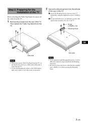
... on a stable work surface. Soft cloth Notes • If you install the right Mounting Hook first, it will be difficult to the rear of the TV temporarily, using the supplied two screws (+PSW4 × 12). 2 Be sure that is larger than the supplied ones (+PSW4 × 12) when securing the Mounting... from the left Mounting Hook first. • Be sure not to use any screws other than the TV. • To prevent damaging the surface of the LCD display, make sure to the rear of the TV. Install the left side of the rear of the TV. 1 Secure the Mounting Hook to adjust its angle.
... on a stable work surface. Soft cloth Notes • If you install the right Mounting Hook first, it will be difficult to the rear of the TV temporarily, using the supplied two screws (+PSW4 × 12). 2 Be sure that is larger than the supplied ones (+PSW4 × 12) when securing the Mounting... from the left Mounting Hook first. • Be sure not to use any screws other than the TV. • To prevent damaging the surface of the LCD display, make sure to the rear of the TV. Install the left side of the rear of the TV. 1 Secure the Mounting Hook to adjust its angle.


