
Service Manual
Page 14
... BU Board 2 Remove 2 HEX screws 3 Disconnect 5 connectors 4 Remove 9 screws Main Bracket 1 BU Board Side Jack Bracket KDL-52V4100/52W4100 BU Shield 2 4 3 1-4. G5 BOARD (POWER UNIT) AND D4Z BOARD, AND D5 BOARD REMOVAL 1 Disconnect 3 connectors 2 Remove 4 screws 3 Disconnect 6 connectors (KDL-52V4100 ONLY) Disconnect 7 connectors (KDL-52W4100 ONLY) 4 Remove 6 screws 5 Release 5 Board Holders 6 Disconnect 5 connectors 7 Remove 4 screws 1 2 5 6 D5 Board 3 4 KDL-52V4100/52W4100 G5 Board (Power Unit) D4Z Board 7 14...
... BU Board 2 Remove 2 HEX screws 3 Disconnect 5 connectors 4 Remove 9 screws Main Bracket 1 BU Board Side Jack Bracket KDL-52V4100/52W4100 BU Shield 2 4 3 1-4. G5 BOARD (POWER UNIT) AND D4Z BOARD, AND D5 BOARD REMOVAL 1 Disconnect 3 connectors 2 Remove 4 screws 3 Disconnect 6 connectors (KDL-52V4100 ONLY) Disconnect 7 connectors (KDL-52W4100 ONLY) 4 Remove 6 screws 5 Release 5 Board Holders 6 Disconnect 5 connectors 7 Remove 4 screws 1 2 5 6 D5 Board 3 4 KDL-52V4100/52W4100 G5 Board (Power Unit) D4Z Board 7 14...
Service Manual
Page 16
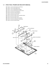
... REMOVAL 1 Remove 1 screw from D5 Support and LCD Panel 2 Remove 1 screw from D5 Support Frame 3 Remove 1 screw from Main Bracket and Bezel 4 Remove 3 screws from Main Bracket and Spine frame 5 Remove 2 screws from Top Vesa Bracket 6 Remove 2 screws from G Board Support 2 7 Remove 2 screws from Center Frame ...and Bezel 11 Remove 4 screws from both Bottom Vesa Brackets 12 Remove 4 screws from Bottom Bracket KDL-52V4100/52W4100 3 2 D5 Support Frame 1 4 Main Bracket Top Vesa Bracket 5 G Board Suport 8 7 Spine Frame Center 6 Frame 9 Bottom Vesa Bracket 11 10 12 Bottom Bracket Bezel...
... REMOVAL 1 Remove 1 screw from D5 Support and LCD Panel 2 Remove 1 screw from D5 Support Frame 3 Remove 1 screw from Main Bracket and Bezel 4 Remove 3 screws from Main Bracket and Spine frame 5 Remove 2 screws from Top Vesa Bracket 6 Remove 2 screws from G Board Support 2 7 Remove 2 screws from Center Frame ...and Bezel 11 Remove 4 screws from both Bottom Vesa Brackets 12 Remove 4 screws from Bottom Bracket KDL-52V4100/52W4100 3 2 D5 Support Frame 1 4 Main Bracket Top Vesa Bracket 5 G Board Suport 8 7 Spine Frame Center 6 Frame 9 Bottom Vesa Bracket 11 10 12 Bottom Bracket Bezel...

Service Manual
Page 26
KDL-52V4100 ONLY BU Board 11 Bracket 10 9 1 2 KDL-52V4100/52W4100 LEGEND SHEET CORE C (2-688-011-01) QTY=11 LCD TAPE (2-688-062-01) QTY=6 SLIDE CLAMP (2-650-770-01) QTY=1 (UPPER VESA SUPPORT) SLIDE CLAMP (2-650-770-11) QTY=12 CHO-FAB TAPE (2-888-494-01) QTY=1 HIMELON TAPE (2-661-260-01) QTY=1 3 4 5 Side Clamps to hold main harness, D5 and G5 harness KDL-52V4100/52W4100 26
KDL-52V4100 ONLY BU Board 11 Bracket 10 9 1 2 KDL-52V4100/52W4100 LEGEND SHEET CORE C (2-688-011-01) QTY=11 LCD TAPE (2-688-062-01) QTY=6 SLIDE CLAMP (2-650-770-01) QTY=1 (UPPER VESA SUPPORT) SLIDE CLAMP (2-650-770-11) QTY=12 CHO-FAB TAPE (2-888-494-01) QTY=1 HIMELON TAPE (2-661-260-01) QTY=1 3 4 5 Side Clamps to hold main harness, D5 and G5 harness KDL-52V4100/52W4100 26

Service Manual
Page 32
... Board bracket. 2 MAKE SURE clip is CENTERED Between Guides on panel BEFORE installing screw. Route LVDS Cable in Slide Clamp. CAUTION: Securing grounding clip with 3x5mm Screw is CRITICAL FOR EMI 1 3 KDL-52V4100/52W4100 LEGEND SHEET CORE C (2-688-011-01) QTY=11 LCD ...TAPE (2-688-062-01) QTY=6 SLIDE CLAMP (2-650-770-01) QTY=1 (UPPER VESA SUPPORT) SLIDE CLAMP (2-650-770-11) QTY=12 CHO-FAB TAPE (2-888-494-01) QTY=1 HIMELON TAPE (2-661-260-01) QTY=1 KDL-52V4100/52W4100 32 MAKE SURE clip is centered between Guides on Main Bracket BEFORE installing 11 Screw. KDL-52V4100...
... Board bracket. 2 MAKE SURE clip is CENTERED Between Guides on panel BEFORE installing screw. Route LVDS Cable in Slide Clamp. CAUTION: Securing grounding clip with 3x5mm Screw is CRITICAL FOR EMI 1 3 KDL-52V4100/52W4100 LEGEND SHEET CORE C (2-688-011-01) QTY=11 LCD ...TAPE (2-688-062-01) QTY=6 SLIDE CLAMP (2-650-770-01) QTY=1 (UPPER VESA SUPPORT) SLIDE CLAMP (2-650-770-11) QTY=12 CHO-FAB TAPE (2-888-494-01) QTY=1 HIMELON TAPE (2-661-260-01) QTY=1 KDL-52V4100/52W4100 32 MAKE SURE clip is centered between Guides on Main Bracket BEFORE installing 11 Screw. KDL-52V4100...

Service Manual
Page 50
... MAKE SURE that the LVDS clip is Centered between guides on Main Bracket and Panel BEFORE applying screw. Route LVDS Cable in Slide Clamp. Clamps are necessary to panel and BU Board bracket. KDL-52V4100/52W4100 LEGEND SHEET CORE C (2-688-011-01) QTY=12 LCD TAPE (2-688-062-01) QTY=4 SLIDE CLAMP (2-650-770-...01) QTY=1 (UPPER VESA SUPPORT) SLIDE CLAMP (2-650-770-11) QTY=11 10 1 9 1 Apply 3x8mm Screw 2 to secure LVDS Cable to keep LVDS cable from touching high-voltage area of D5-Bd. LVDS CLIP/SCREW IS CRITICAL FOR EMI KDL-52V4100/...
... MAKE SURE that the LVDS clip is Centered between guides on Main Bracket and Panel BEFORE applying screw. Route LVDS Cable in Slide Clamp. Clamps are necessary to panel and BU Board bracket. KDL-52V4100/52W4100 LEGEND SHEET CORE C (2-688-011-01) QTY=12 LCD TAPE (2-688-062-01) QTY=4 SLIDE CLAMP (2-650-770-...01) QTY=1 (UPPER VESA SUPPORT) SLIDE CLAMP (2-650-770-11) QTY=11 10 1 9 1 Apply 3x8mm Screw 2 to secure LVDS Cable to keep LVDS cable from touching high-voltage area of D5-Bd. LVDS CLIP/SCREW IS CRITICAL FOR EMI KDL-52V4100/...
Service Manual
Page 60
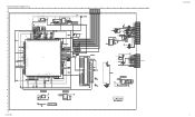
... R3402 6.8k 1/16W RN-CP 0.5% R3403 15k 1/16W 0.5% GND DC_DET MAIN-BU-ALERT SIRCS STBY3.3V 1005 X7R 50V 0.001 C3202 1357 7531 2468 8642... . 8 k 14 VIN 15 B INT 16 RXD 17 TXD 18 GND GND TL-Board DC_ALERT REG5V R3420 10k 1/16W CHIP 5% 1005 Q3415 RT3N11M-TP-1 GND SCL_RTC SDA_RTC STBY3....XRSTIN 4 XINIT 5 BREAK 6 ICD3 7 ICD2 8 ICD1 9 ICD0 10 ICS2 11 ICS1 12 ICS0 13 GND 14 ICLK CN3001 14P KDL-52V4100/52W4100 KDL-52V4100/52W4100 60 H - J - D - F - L - P C3006 0.1 16V 1005 > RESET 2 VDD C3 1 GND ...A17/P51 56 A16/P50 55 VDDI 54 VSS 53 VDDE 52 A15 51 A14 50 A13 49 A12 48 A11 47 A10...
... R3402 6.8k 1/16W RN-CP 0.5% R3403 15k 1/16W 0.5% GND DC_DET MAIN-BU-ALERT SIRCS STBY3.3V 1005 X7R 50V 0.001 C3202 1357 7531 2468 8642... . 8 k 14 VIN 15 B INT 16 RXD 17 TXD 18 GND GND TL-Board DC_ALERT REG5V R3420 10k 1/16W CHIP 5% 1005 Q3415 RT3N11M-TP-1 GND SCL_RTC SDA_RTC STBY3....XRSTIN 4 XINIT 5 BREAK 6 ICD3 7 ICD2 8 ICD1 9 ICD0 10 ICS2 11 ICS1 12 ICS0 13 GND 14 ICLK CN3001 14P KDL-52V4100/52W4100 KDL-52V4100/52W4100 60 H - J - D - F - L - P C3006 0.1 16V 1005 > RESET 2 VDD C3 1 GND ...A17/P51 56 A16/P50 55 VDDI 54 VSS 53 VDDE 52 A15 51 A14 50 A13 49 A12 48 A11 47 A10...

Service Manual
Page 75
B - F - C - G - I - ☛G5 BOARD SCHEMATIC DIAGRAM 1 | 2 | 3 | 4 | 5 | 6 | 7 | 8 | 9 | 10 | 11 | 12 | 13 | 14 | 15 | 16 | 17 | 18 | 19 | 20 | 21 |...STBY3.3V 2 AC_OFF_DET 1 POWER_ON CN6150 13P TO BU GND_1 1 REG12V 2 REG12V 3 REG12V_GND 4 REG12V_GND CN6100 4P TO TCON (KDL-52W4100 C6159 3300 25V R6158 47k 1/10W RN-CP MAIN FB 4 1 3 2 PH6100 PC123Y22FZW TMP R6150 680 1/10W RN-CP 5% R6151 1k 1/10W RN-CP 5% R6153 0...C6407 1 25V X7R R6403 1k TMP D6401 MA113 PROT1 G5 POWER A-1511-323-A G5 KDL-52V4100/52W4100 KDL-52V4100/52W4100 75 D -
B - F - C - G - I - ☛G5 BOARD SCHEMATIC DIAGRAM 1 | 2 | 3 | 4 | 5 | 6 | 7 | 8 | 9 | 10 | 11 | 12 | 13 | 14 | 15 | 16 | 17 | 18 | 19 | 20 | 21 |...STBY3.3V 2 AC_OFF_DET 1 POWER_ON CN6150 13P TO BU GND_1 1 REG12V 2 REG12V 3 REG12V_GND 4 REG12V_GND CN6100 4P TO TCON (KDL-52W4100 C6159 3300 25V R6158 47k 1/10W RN-CP MAIN FB 4 1 3 2 PH6100 PC123Y22FZW TMP R6150 680 1/10W RN-CP 5% R6151 1k 1/10W RN-CP 5% R6153 0...C6407 1 25V X7R R6403 1k TMP D6401 MA113 PROT1 G5 POWER A-1511-323-A G5 KDL-52V4100/52W4100 KDL-52V4100/52W4100 75 D -
Service Manual
Page 85
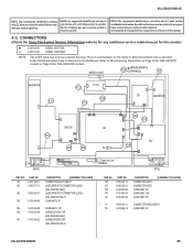
.... Refer to the BU Board. PART NO. * 101 102 1-835-149-11 1-835-271-11 102 1-835-263-11 103 1-910-044-00 DESCRIPTION [ASSEMBLY INCLUDES] CONNECTOR ASSY, MDF61 LEAD WIRE WITH CONNECTOR (LVDS) (KDL-52V4100 ONLY) LEAD WIRE WITH CONNECTOR (LVDS) (KDL-52W4100 ONLY) CONN ASSY,... ! sont critiques pour la securite. CONNECTORS (Check the Sony Electronics Service Information website for any additional service related issues for KDL-52W4100 models. SWITCH UNIT (MAIN BRKT) 102 (PANEL) 101 INVERTER 111 T-CON 112 106 107 D5 INVERTER a a D4Z-52 G5 a a 110 109 108 AC 104 103 BU...
.... Refer to the BU Board. PART NO. * 101 102 1-835-149-11 1-835-271-11 102 1-835-263-11 103 1-910-044-00 DESCRIPTION [ASSEMBLY INCLUDES] CONNECTOR ASSY, MDF61 LEAD WIRE WITH CONNECTOR (LVDS) (KDL-52V4100 ONLY) LEAD WIRE WITH CONNECTOR (LVDS) (KDL-52W4100 ONLY) CONN ASSY,... ! sont critiques pour la securite. CONNECTORS (Check the Sony Electronics Service Information website for any additional service related issues for KDL-52W4100 models. SWITCH UNIT (MAIN BRKT) 102 (PANEL) 101 INVERTER 111 T-CON 112 106 107 D5 INVERTER a a D4Z-52 G5 a a 110 109 108 AC 104 103 BU...


