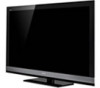
Child Safety: It Makes A Difference Where Your TV Stands
Page 1
... does NOT fit all. As a result, TV sets may fall over . 7 Share our safety message on this hidden hazard of television and consumer electronics furniture manufacturers to secure your family and friends. Use the appropriate furniture that children can become excited while watching a program... and can potentially push or pull a TV over and may cause unnecessary injury. Sometimes televisions are improperly secured or inappropriately situated on the proper TV stands. The home theater entertainment experience is committed to climb on or...
Safety and Regulatory Booklet
Page 1
...glass with high‑precision technology and to perform routine safety checks as your eyes or mouth. Outdoor use . Do not pull by Sony and to your outlet, consult an electrician for signs of children's reach. Unplugging the AC power cord from the wall outlet will ... in the literature accompanying the TV. Consulte el reverso para obtener más información. Using incorrect replacement batteries can easily be observed when the LCD TV is intended to alert the user to use of a Wall‑Mount Bracket. However, uneven brightness may cause a malfunction. ☐ If...
Limited Warranty (U.S. Only)
Page 1
...user purchase is required to determine coverage. These are covered. This Limited Warranty is exchanged, the original item becomes SONY's property. Any software is longer. (See reverse for warranty service. Product Coverage: Only the hardware components packaged with...Sony Customer Information Service Center 1-800-222-SONY (7669) For an accessory or part not available from original date of this Limited Warranty, SONY will not reimburse You for the coverage, duration and terms of protection to the service plan for service performed by SONY. 4-144-386-01(2) LCD Television...
Limited Warranty (U.S. Only)
Page 2
... use of God or nature; (ii) misuse; (iii) accidental damage, including contact with the owner's manual and other SONY instruction; (ix) use ; SONY specifically does not represent that do not allow the exclusion or limitation of programs or data. Some states do not function normally...use or installation inconsistent with liquid, extreme heat or foreign material; (iv) customer installation, set up to You. LIMITATION ON DAMAGES: SONY SHALL NOT BE LIABLE FOR ANY INCIDENTAL OR CONSEQUENTIAL DAMAGES FOR BREACH OF ANY EXPRESS OR IMPLIED WARRANTY ON THIS PRODUCT NOR SHALL RECOVERY OF...
Additional Informatino for Using Sony® Wall-Mount Bracket (SU-WL500)
Page 1
...for this Wall-Mount Bracket information: KDL-60NX800/KDL-55HX701/KDL-46HX701/KDL-40HX701/KDL-60EX703/KDL-52EX703/ KDL-46EX703/KDL-40EX703/KDL-60EX701/KDL-52EX701/KDL-46EX701/KDL-60EX700/ KDL-52EX700/KDL-46EX700/KDL-40EX700/KDL-32EX700/KDL-32EX308 For product protection and safety reasons, Sony strongly recommends that you use the ... Additional Information for safety and proper installation. Read these documents carefully for Using Sony Wall-Mount Bracket (SU-WL500) − − Sony is performed by mishandling or improper installation. For proper installation, follow your wall...
Additional Informatino for Using Sony® Wall-Mount Bracket (SU-WL500)
Page 2
... to each model. Dimension Table (except KDL-32EX*) (KDL-32EX* only) Screen center point Unit: inches (mm) Model Name KDL-60NX800 KDL-55HX701 KDL-46HX701 KDL-40HX701 KDL60EX70* KDL52EX70* KDL46EX70* KDL40EX70* KDL32EX70* KDL-32EX308 Display dimensions ...) Screen center dimensions 1 1/4 (31) /31 32 (25) 3 3/8 (84) 4 7/8 (122) 1 1/4 (31) 3 1/4 (82) 4 7/8 (121) 6 1/4 (158) 7 7/8 (197) 6 7/8 (172) Length for Using Sony Wall-Mount Bracket (SU-WL500) − −
Additional Informatino for Using Sony® Wall-Mount Bracket (SU-WL500)
Page 3
... Determine the screw locations and secure the Mounting Hooks to the rear of the TV. KDL‑HX*, KDL‑32EX30*only Square hole Mounting Hook Screw (+PSW6 × 16) KDL-EX70* only Before installing, remove screws Square hole Mounting Hook Screw (+...times that of the TV. Refer to the "Screw and Hook Locations Diagram/Table" shown below. Refer to your TV's operating instructions for Using Sony Wall-Mount Bracket (SU-WL500) − − CAUTION The wall that the TV will be installed on the wall.
Additional Informatino for Using Sony® Wall-Mount Bracket (SU-WL500)
Page 4
... four spacers and four M6 × 20 screws. When attaching the Table-Top Stand again, be sure to fasten the removed screws to each model. KDL-60NX800 only Remove the bottom cover and terminal cover. Mounting Hook Screw (M6 × 20) ✍ • Place the TV on the Table-Top Stand... the rear of the TV. Be sure to store the removed screws in the wall mounting holes from the rear of the TV (KDL-EX70* and KDL-60NX800 only). * In the actual model names, the "" indicates numbers and/or characters specific to the original holes on a wall, remove...
Additional Informatino for Using Sony® Wall-Mount Bracket (SU-WL500)
Page 5
... Locations Diagram/Table Model Name Screw Locations KDL-60NX800/KDL-60EX70* e, j KDL-55HX701 d, g KDL-46HX701/KDL-40HX701 d, g KDL‑52EX70*/KDL‑46EX70*/ e, j KDL‑40EX70* KDL-32EX700 f, j KDL-32EX308 e, g * In the actual model names, the "" indicates numbers and/or characters specific to each model. Additional Information for Using Sony Wall-Mount Bracket (SU-WL500) − −...
Additional Informatino for Using Sony® Wall-Mount Bracket (SU-WL500)
Page 6
Do not remove any other screws from the back of the TV. KDL‑32EX7*, KDL‑40EX7* only * In the actual model names, the "" indicates numbers and/or characters specific to lift the TV by yourself. Do ...not attempt to each model. 8 Lift the TV off the stand. Additional Information for Using Sony Wall-Mount Bracket (SU-WL500) − −...
Additional Informatino for Using Sony® Wall-Mount Bracket (SU-WL500)
Page 7
Refer to the Instructions for Using Sony Wall-Mount Bracket (SU-WL500) − − Additional Information for SU-WL500. ✍ • When you put the TV back on the stand, reverse the above steps. • Remove the screws or install the Mounting Hook on the wall. 9 Install the TV on a stable and level surface.
Setup Guide (Operating Instructions)
Page 1
LCD Digital Color TV Setup Guide (Operating Instructions) 4-178-827-13(1) Setting up your TV To watch TV Additional Information Sony Customer Support U.S.A.: www.sony.com/tvsupport Canada: www.sony.ca/support United States Canada 1.800.222.SONY 1.877.899.SONY Please Do Not Return the Product to the Store KDL-60EX700 / 60EX701 / 60EX703 / 52EX700 / 52EX701 / 52EX703 KDL-46EX700 / 46EX701 / 46EX703 / 40EX700 / 40EX703 / 32EX700
Setup Guide (Operating Instructions)
Page 2
...; 6,396,546; 5,940,073; 6,239,794 to Gemstar-TV Guide International, Inc. Licensing Information Macintosh is a trademark of Sony Corporation. and/or its subsidiaries. Your new BRAVIA® TV opens the door to the "Full HDTV Experience." Please take a moment to register your TV. definition (HD)...serial numbers are located at : U.S.A.: http://productregistration.sony.com Canada: http://www.SonyStyle.ca/registration Four Steps to a Full HD Experience Set, Source, Sound, and Setup. 1 Set Now that you have made the best selection in LCD TV technology, be sure to remove all video ...
Setup Guide (Operating Instructions)
Page 3
Refer to "To use i-Manual...15 Additional Information Troubleshooting ...16 Specifications ...18 • Operating instructions are built into the remote control 4 Setting up your BRAVIA TV. Table of Contents Checking the accessories...4 Inserting batteries into your TV Attaching the Table-Top Stand...5 Connecting the TV...6 Securing the TV...10 Organizing ...
Setup Guide (Operating Instructions)
Page 4
...Stand Rear Cover is attached to the TableTop Stand for 46, 52 and 60 inch models. *3 Please refer to open. 4 Guidelines for KDL-60EX701/52EX701/46EX701 models) *1 The 32" and 40" models require assembling. Inserting batteries into the remote control Slide the cover to the ...) Stand Rear Cover (1)*2 Fixing screws for Table-Top Stand (M5 × 16) (4) (except KDL-60EX700/ 60EX701/60EX703 models) Assembling Screws for Table-Top Stand (M5 × 16) (4) (for KDL-40EX700/ 40EX703/32EX700 models) Remote control (1)*3 Size AAA batteries (2) USB Wireless LAN Adapter UWA-BR100 (1) (for Remote ...
Setup Guide (Operating Instructions)
Page 5
... the screw holes. ~ • Do not put stress on with the adequate number of the 32" and 40" models. Attaching the Table-Top Stand (except KDL-60EX700/60EX701/ 60EX703 models) Refer to the Table-Top Stand. ~ • If you use an electric screwdriver, set the tightening torque at approximately 1.5 N·m {15... your hands or the AC power cord when you can attach the TV to the Table-Top Stand with the Stand Rear Cover on the LCD panel or the frame around the screen. • Be careful to not pinch your TV: • Disconnect all the screws are packaged with the supplied...
Setup Guide (Operating Instructions)
Page 6
Recommendation of the F type plug Projection of the inner wire from the connection part must be less than 1.5 mm. 1.5 mm 6 Connecting the TV The following chart shows the high-definition (HD) and standard-definition (SD) video formats supported by your BRAVIA TV inputs. * For supported PC formats refer to the i-Manual.
Setup Guide (Operating Instructions)
Page 7
Setting up your TV Shown with a Set Top Box with HDMI connection Shown with a Set Top Box with COMPONENT connection Set Top Box Set Top Box Cable System or VHF/UHF Antenna System Cable or Antenna (Continued) 7
Setup Guide (Operating Instructions)
Page 8
Shown with HD Basic Connection with HD BRAVIA® Sync™ Basic Connection *Rear of TV Home Theater System Cable/ Antenna Cable/SAT (Dish) SD Cable Box or SD Satellite Receiver 8 or Blu-... COMPONENT VIDEO OUT Y PB/CB DIGITAL OUT PCM/DTS/DOLBY DIGITAL COAXIAL OPTICAL S VIDEO PR/CR AUDIO OUT L 5.1CH OUTPUT FRONT REAR CENTER L R R WOOFER * Signifies a BRAVIA Sync capable device.
Setup Guide (Operating Instructions)
Page 9
Setting up your TV Shown with PC Connection with SD VCR/DVD Rear of TV Notebook PC or Splitter PC VCR VCR/DVD Combo DVD Cable/Antenna 9