
Instructions (SU-PW3M Wall-Mount Bracket)
Page 7
...B6 × L20) (4) Screw (+PSW5 × L14) (6) 7 (US) Step 2: Decide on the installation location 1 Place the paper template on a perpendicular, flat wall and decide on the paper template. Unit: mm (inches) 300 (11 13⁄16) Plate Unit (1) Woofer Speaker 100 (3 15⁄16) Hook (4) ... beforehand. 2 Open the package and check the parts. For details, refer to make a hole in the diagram below. The position for suitable clearance between the TV and the ceiling and protruding parts of the paper template together with commercially available adhesive tape. Note If you ...
...B6 × L20) (4) Screw (+PSW5 × L14) (6) 7 (US) Step 2: Decide on the installation location 1 Place the paper template on a perpendicular, flat wall and decide on the paper template. Unit: mm (inches) 300 (11 13⁄16) Plate Unit (1) Woofer Speaker 100 (3 15⁄16) Hook (4) ... beforehand. 2 Open the package and check the parts. For details, refer to make a hole in the diagram below. The position for suitable clearance between the TV and the ceiling and protruding parts of the paper template together with commercially available adhesive tape. Note If you ...
Instructions (SU-PW3M Wall-Mount Bracket)
Page 8
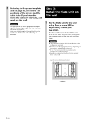
... Unit to the wall using four or more M8 (or equivalent) screws (not supplied). Step 3: Install the Plate Unit on . WARNING The wall that the TV will be installed on the wall. Align the unit so that the Plate Unit is exactly level. 2 Referring to the paper template and on page... in the wall), and work on should be capable of supporting a weight of at least four screw holes with the same mark shown in the diagram below, and tighten the screws securely so that they will not come loose. Reinforce the wall sufficiently, if necessary. WARNING • The screws securing the...
... Unit to the wall using four or more M8 (or equivalent) screws (not supplied). Step 3: Install the Plate Unit on . WARNING The wall that the TV will be installed on the wall. Align the unit so that the Plate Unit is exactly level. 2 Referring to the paper template and on page... in the wall), and work on should be capable of supporting a weight of at least four screw holes with the same mark shown in the diagram below, and tighten the screws securely so that they will not come loose. Reinforce the wall sufficiently, if necessary. WARNING • The screws securing the...
Instructions (SU-PW3M Wall-Mount Bracket)
Page 17
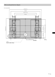
Wall processing dimensions diagram Unit: mm (inches) 670 (26 3/8) 610 (24) 455 (17 15/16) 406 (16) 393 ± 0.5 (15 15/32 ± 5/256) 131 (5 5/32) 420 (16 17/32) 131 (5 5/32) 65.5 (2 37/64) ø 75 (3) Hole for cable routing 20 - 9 × 20 (23/64 × 5/6) Slot hole 13.5 (17/32) 17 (US)
Wall processing dimensions diagram Unit: mm (inches) 670 (26 3/8) 610 (24) 455 (17 15/16) 406 (16) 393 ± 0.5 (15 15/32 ± 5/256) 131 (5 5/32) 420 (16 17/32) 131 (5 5/32) 65.5 (2 37/64) ø 75 (3) Hole for cable routing 20 - 9 × 20 (23/64 × 5/6) Slot hole 13.5 (17/32) 17 (US)
Operating Instructions
Page 57
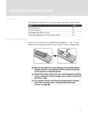
... Remote Control" on the batteries to set up, program, and use the remote control. Using the Remote Control Overview This chapter describes how to the diagram inside the remote control's battery compartment.
... Remote Control" on the batteries to set up, program, and use the remote control. Using the Remote Control Overview This chapter describes how to the diagram inside the remote control's battery compartment.

Quick Setup Guide
Page 1
...THE STORE. Note The connection diagrams shown in right. The Initial Setup screen appears. 2 Press V or v to be very complex, so check your product is listed, use CableCARD™ service, you plan to complete. 2-189-525-12 (1) KDE-37XS955 KDE-42XS955 KDE-50XS955 Quick Setup Guide Please follow...1080i/720p/480p/480i) KDE-37/42XS955 KDE-50XS955 Note Inserting the CableCARD™ incorrectly may take up to 50 minutes or more than Sony brand that include an AV receiver can use the number listed first.) DVD/ SAT/ POWER MUTING VCR CABLE MODE TV/ PICTURE WIDE DISPLAY VIDEO...
...THE STORE. Note The connection diagrams shown in right. The Initial Setup screen appears. 2 Press V or v to be very complex, so check your product is listed, use CableCARD™ service, you plan to complete. 2-189-525-12 (1) KDE-37XS955 KDE-42XS955 KDE-50XS955 Quick Setup Guide Please follow...1080i/720p/480p/480i) KDE-37/42XS955 KDE-50XS955 Note Inserting the CableCARD™ incorrectly may take up to 50 minutes or more than Sony brand that include an AV receiver can use the number listed first.) DVD/ SAT/ POWER MUTING VCR CABLE MODE TV/ PICTURE WIDE DISPLAY VIDEO...
Quick Setup Guide
Page 2
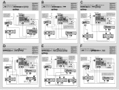
... satellite receiver has a HDMI jack, use that instead of the video connections shown here. DVD Player C Use this diagram if you have ; Cable Splitter Cable Box or Satellite Receiver IN OUT Rear of TV 6 R-AUDIO -L VIDEO IN 1 3 R-AUDIO -L (MONO) VIDEO S VIDEO 4 CENTER SPEAKER IN 180W (6 ) MAX CONTROL...IN LINE OUT OUT R L AUDIO VIDEO Sony Dream System VIDEO 1 VIDEO 2 MONITOR OUT AUDIO OUT VIDEO OUT AUDIO IN VIDEO IN R L R L R L AUDIO IN VIDEO IN Y PB/CB PR/CR COMPONENT VIDEO OUT S VIDEO B Use this diagram if you have ; Cable Splitter High ...
... satellite receiver has a HDMI jack, use that instead of the video connections shown here. DVD Player C Use this diagram if you have ; Cable Splitter Cable Box or Satellite Receiver IN OUT Rear of TV 6 R-AUDIO -L VIDEO IN 1 3 R-AUDIO -L (MONO) VIDEO S VIDEO 4 CENTER SPEAKER IN 180W (6 ) MAX CONTROL...IN LINE OUT OUT R L AUDIO VIDEO Sony Dream System VIDEO 1 VIDEO 2 MONITOR OUT AUDIO OUT VIDEO OUT AUDIO IN VIDEO IN R L R L R L AUDIO IN VIDEO IN Y PB/CB PR/CR COMPONENT VIDEO OUT S VIDEO B Use this diagram if you have ; Cable Splitter High ...