Dimensions Diagrams
Page 1
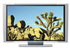
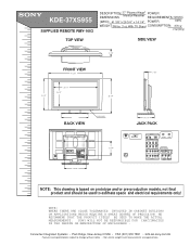
KDE-37XS955 SUPPLIED REMOTE RMY-1003 TOP VIEW MDDEEOSSDCCERRLII:PPTTIIOONN:: DIMENSIONS 37" Plasma Wega® Monitor/Receiver POWER REQUIREMENTS:120VAC (W(WWEHHIGDDH))::T4: 1 3/8 "x 26 3/4 " x 14 1/4" WEIGHT: 99 lbs 3 oz With TV Stand POWER CONSUMPTION: 60Hz 370 w
KDE-37XS955 SUPPLIED REMOTE RMY-1003 TOP VIEW MDDEEOSSDCCERRLII:PPTTIIOONN:: DIMENSIONS 37" Plasma Wega® Monitor/Receiver POWER REQUIREMENTS:120VAC (W(WWEHHIGDDH))::T4: 1 3/8 "x 26 3/4 " x 14 1/4" WEIGHT: 99 lbs 3 oz With TV Stand POWER CONSUMPTION: 60Hz 370 w

Instructions (SU-PW3M Wall-Mount Bracket)
Page 5
... or is removed after installing it is necessary to continue to use the appropriate screws for Sony Dealers only. Do not allow the AC power cord or the connecting cable to read safety precautions described above the TV may become exposed and cause a short circuit or an electrical break. Consult your contractor regarding...
... or is removed after installing it is necessary to continue to use the appropriate screws for Sony Dealers only. Do not allow the AC power cord or the connecting cable to read safety precautions described above the TV may become exposed and cause a short circuit or an electrical break. Consult your contractor regarding...
Instructions (SU-PW3M Wall-Mount Bracket)
Page 10
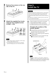
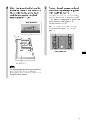
...not remove) the screws. WARNING Be sure to complete the installation before connecting the AC power cord to stumble over the AC power cord or the TV, as damage may hurt yourself. 1 When installing a 50-inch TV on the Wall- If you fail to slide the woofer speaker completely in step 2, the... Retighten the four screws (loosened in product damage. 10 (US) Soft rag Note If you allow the AC power cord to be blocked resulting in step 1) to change the position of the TV. Changing the position of the woofer speaker. 1 Loosen the four screws (two on each side of equipment, ...
...not remove) the screws. WARNING Be sure to complete the installation before connecting the AC power cord to stumble over the AC power cord or the TV, as damage may hurt yourself. 1 When installing a 50-inch TV on the Wall- If you fail to slide the woofer speaker completely in step 2, the... Retighten the four screws (loosened in product damage. 10 (US) Soft rag Note If you allow the AC power cord to be blocked resulting in step 1) to change the position of the TV. Changing the position of the woofer speaker. 1 Loosen the four screws (two on each side of equipment, ...
Instructions (SU-PW3M Wall-Mount Bracket)
Page 11
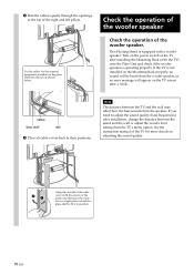
... Rack. Soft rag Rear side of the TV Note The woofer speaker joint is securely connected to the TV. Connect the AC power cord and the connecting cable(s) to the connectors on connecting the AC power cord and the connecting cable(s), refer to the TV. For details on the rear side of ...the TV. Hole for cable routing 11 (US) Then slide...
... Rack. Soft rag Rear side of the TV Note The woofer speaker joint is securely connected to the TV. Connect the AC power cord and the connecting cable(s) to the connectors on connecting the AC power cord and the connecting cable(s), refer to the TV. For details on the rear side of ...the TV. Hole for cable routing 11 (US) Then slide...
Instructions (SU-PW3M Wall-Mount Bracket)
Page 12
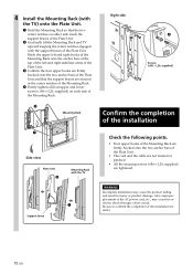
...AC power cord, etc., may cause the product falling and result in the center notches of the Mounting Rack. 4 Firmly tighten all four upper and lower screws (+B6 × L20, supplied) on either side touch the support braces of the Plate Unit. 2 Gradually lift the Mounting Rack and TV upward...Plate Unit and that the two center notches on each side of the Mounting Rack. 2 Mounting Rack 1 Side view Plate Unit 2 Mounting Rack with the TV 1 Support brace Right side 4 Screws (+B6 × L20, supplied) Confirm the completion of the installation Check the following points. • Four upper ...
...AC power cord, etc., may cause the product falling and result in the center notches of the Mounting Rack. 4 Firmly tighten all four upper and lower screws (+B6 × L20, supplied) on either side touch the support braces of the Plate Unit. 2 Gradually lift the Mounting Rack and TV upward...Plate Unit and that the two center notches on each side of the Mounting Rack. 2 Mounting Rack 1 Side view Plate Unit 2 Mounting Rack with the TV 1 Support brace Right side 4 Screws (+B6 × L20, supplied) Confirm the completion of the installation Check the following points. • Four upper ...
Instructions (SU-PW3M Wall-Mount Bracket)
Page 13
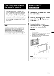
... Rack properly, no sound will be heard from the woofer speaker, or an error message will appear on the TV screen after a while. 1 Unplug the AC power cord from the TV's menu option. After installing the Mounting Rack (with a woofer speaker. Check the operation of the woofer speaker ...Remove the TV For Sony Dealers This Wall-Mount Bracket is equipped with the TV) onto the Plate Unit, turn on the power switch of the TV and check if ...
... Rack properly, no sound will be heard from the woofer speaker, or an error message will appear on the TV screen after a while. 1 Unplug the AC power cord from the TV's menu option. After installing the Mounting Rack (with a woofer speaker. Check the operation of the woofer speaker ...Remove the TV For Sony Dealers This Wall-Mount Bracket is equipped with the TV) onto the Plate Unit, turn on the power switch of the TV and check if ...

Instructions (SU-PW3M Wall-Mount Bracket)
Page 14
... braces with your hands or fingers. Support braces 2 3 3 14 (US) Connect the external equipment cables to the TV after installation For Customers, Sony Dealers 1 Tilt the TV upward. 1 Unplug the AC power cord. 2 Unfasten the two securing screws at the outer sides of the bottom left and right hooks of the Mounting...so that all the cables connected to the TV are not twisted or pinched, and then plug in the AC power cord. Notes • Do not hold the transparent part of the TV. • Do not let go of the TV while lifting it, otherwise the TV may hit the wall and cause damage. ...
... braces with your hands or fingers. Support braces 2 3 3 14 (US) Connect the external equipment cables to the TV after installation For Customers, Sony Dealers 1 Tilt the TV upward. 1 Unplug the AC power cord. 2 Unfasten the two securing screws at the outer sides of the bottom left and right hooks of the Mounting...so that all the cables connected to the TV are not twisted or pinched, and then plug in the AC power cord. Notes • Do not hold the transparent part of the TV. • Do not let go of the TV while lifting it, otherwise the TV may hit the wall and cause damage. ...

Instructions (SU-PW3M Wall-Mount Bracket)
Page 15
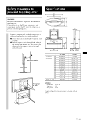
PLATE UNIT 79 (3 1⁄8) ø 90 (3 5⁄8) 670 (26 3⁄8) MOUNTING RACK 505 (19 29⁄32)* 520 (20 1⁄2) 44 85.5 (1 3⁄4) (3 3⁄8) * When changing the position of the woofer speaker for installing a 50-inch TV: 590 (23 1/4) SPEAKER Speaker unit Impedance Max. Specifications Unit: mm (inches) Weight: 15.0 kg (33 lb 1 oz) Design and specifications are subject to change without notice. power 10 cm (2) 4 Ω 50 W 420 (16 17⁄32) 480 (18 29⁄32) 15 (US)
PLATE UNIT 79 (3 1⁄8) ø 90 (3 5⁄8) 670 (26 3⁄8) MOUNTING RACK 505 (19 29⁄32)* 520 (20 1⁄2) 44 85.5 (1 3⁄4) (3 3⁄8) * When changing the position of the woofer speaker for installing a 50-inch TV: 590 (23 1/4) SPEAKER Speaker unit Impedance Max. Specifications Unit: mm (inches) Weight: 15.0 kg (33 lb 1 oz) Design and specifications are subject to change without notice. power 10 cm (2) 4 Ω 50 W 420 (16 17⁄32) 480 (18 29⁄32) 15 (US)

Instructions for Floating Stand (SU-PF3M/SU-PF3L)
Page 3
...the Floating Stand may topple over the designated location beforehand. • Do not allow the AC power cord or the connecting cable to prevent English the stand from the TV Installation by qualified Sony service representatives. US Be sure to take measures to be installed by other, non-qualified persons ...result. The stand may topple over . Do not allow the AC power cord or the connecting cable to prevent it leans in fire or electric shock. • Do not step on a solid and flat floor. Anchor the TV to the wall to be damaged, and this may result in it....
...the Floating Stand may topple over the designated location beforehand. • Do not allow the AC power cord or the connecting cable to prevent English the stand from the TV Installation by qualified Sony service representatives. US Be sure to take measures to be installed by other, non-qualified persons ...result. The stand may topple over . Do not allow the AC power cord or the connecting cable to prevent it leans in fire or electric shock. • Do not step on a solid and flat floor. Anchor the TV to the wall to be damaged, and this may result in it....
Instructions for Floating Stand (SU-PF3M/SU-PF3L)
Page 6
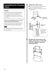
... to be pinched under or between pieces of the Floating Stand. Since the TV is heavy, it is recommended that you stumble over the AC power cord or the connecting cable, the stand may result in a short circuit or an electric shock. The rubber footings on the base of the Floating ... the hole at the bottom of the Floating Stand and detach the cable cover. 2 Position the rear panel on the pillars and secure on the floor. Cable cover for rear side of the TV Cable cover for the pillars of equipment, this may topple over and cause injury. Note Do not push...
... to be pinched under or between pieces of the Floating Stand. Since the TV is heavy, it is recommended that you stumble over the AC power cord or the connecting cable, the stand may result in a short circuit or an electric shock. The rubber footings on the base of the Floating ... the hole at the bottom of the Floating Stand and detach the cable cover. 2 Position the rear panel on the pillars and secure on the floor. Cable cover for rear side of the TV Cable cover for the pillars of equipment, this may topple over and cause injury. Note Do not push...
Instructions for Floating Stand (SU-PF3M/SU-PF3L)
Page 9
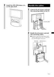
Cable band Cable band screw 9 (US) 2 Install the VCR, DVD player, etc., on the glass shelf. Bundle the cables 1 Connect the AC power cord and the connecting cables to the Floating Stand with the supplied screw (TP4 × 16) and pass the cables through the cable band. Connecting cables 2 Bundle the AC power cord and the connecting cables. 1 Attach the cable band to the TV.
Cable band Cable band screw 9 (US) 2 Install the VCR, DVD player, etc., on the glass shelf. Bundle the cables 1 Connect the AC power cord and the connecting cables to the Floating Stand with the supplied screw (TP4 × 16) and pass the cables through the cable band. Connecting cables 2 Bundle the AC power cord and the connecting cables. 1 Attach the cable band to the TV.
Instructions for Floating Stand (SU-PF3M/SU-PF3L)
Page 10
... wall or adjust the woofer level setting from the woofer speaker, or an error message will be heard from the TV's menu option. If the TV is operating properly. Turn on the power switch of the pillar, and then give the cable cover a slight press toward the glass shelf to adjust the... sound quality (bass frequencies) after installation, change the distance between the TV and the wall may affect how the bass sounds from the speaker. This ...
... wall or adjust the woofer level setting from the woofer speaker, or an error message will be heard from the TV's menu option. If the TV is operating properly. Turn on the power switch of the pillar, and then give the cable cover a slight press toward the glass shelf to adjust the... sound quality (bass frequencies) after installation, change the distance between the TV and the wall may affect how the bass sounds from the speaker. This ...
Instructions for Floating Stand (SU-PF3M/SU-PF3L)
Page 11
... anchor attachments and then tighten the other end of the rope or chain to prevent it from toppling over. power 10 cm (2) 4 Ω 50 W Design and specifications are subject to do so, the TV may topple over and cause injury. CD E I J K L Weight: kg (oz) SU-PF3M 975 (...(20 5/8) 327 (12 7/8) 691 (27 1/4) 480 (19) 115 (4 1/2) 1189 (46 7/8) 244 (9 5/8) 184 (7 1/4) 36 (1270) SPEAKER Speaker unit Impedance Max. Anchor the TV to a wall, pillar, etc., to the wall anchor bracket. Safety measures to prevent toppling over Specifications A B WARNING Be sure to take measures to prevent the...
... anchor attachments and then tighten the other end of the rope or chain to prevent it from toppling over. power 10 cm (2) 4 Ω 50 W Design and specifications are subject to do so, the TV may topple over and cause injury. CD E I J K L Weight: kg (oz) SU-PF3M 975 (...(20 5/8) 327 (12 7/8) 691 (27 1/4) 480 (19) 115 (4 1/2) 1189 (46 7/8) 244 (9 5/8) 184 (7 1/4) 36 (1270) SPEAKER Speaker unit Impedance Max. Anchor the TV to a wall, pillar, etc., to the wall anchor bracket. Safety measures to prevent toppling over Specifications A B WARNING Be sure to take measures to prevent the...

Operating Instructions
Page 3
...Continued) 1 If this Plasma Display Panel may be fully inserted to which can become imprinted on the cord. s Consult the dealer or an experienced radio/TV technician for other outlet unless the blades can be blurred or show poor color due to direct illumination or direct sunlight... Code (NEC) that interference will become permanently imprinted onto the screen. Safety s Operate the TV only on page 2. This symbol is designed, for several days, disconnect the power by turning the equipment off and on a circuit different from the broadcaster/cable company and/or...
...Continued) 1 If this Plasma Display Panel may be fully inserted to which can become imprinted on the cord. s Consult the dealer or an experienced radio/TV technician for other outlet unless the blades can be blurred or show poor color due to direct illumination or direct sunlight... Code (NEC) that interference will become permanently imprinted onto the screen. Safety s Operate the TV only on page 2. This symbol is designed, for several days, disconnect the power by turning the equipment off and on a circuit different from the broadcaster/cable company and/or...

Operating Instructions
Page 4
...into the outlet, try reversing the plug. If you plug/unplug the AC power cord from SRS Labs, Inc. SONY APPLIANCE MODEL NO. SU-PF3L (for KDE-50XS955) SU-PF3M (for KDE-37/42XS955) To Customers Sufficient expertise is trademark of Cable Television Laboratories, Inc. ... . KDE-37XS955 KDE-42XS955 KDE-50XS955 SONY WALL-MOUNT BRACKET MODEL NO. Important Safeguards Before using your TV, please read and follow the instructions supplied with a wet hand. Grounding or Polarization This unit is a trademark of Sony Corporation. Wall outlet Do not use of electrical power supplied ...
...into the outlet, try reversing the plug. If you plug/unplug the AC power cord from SRS Labs, Inc. SONY APPLIANCE MODEL NO. SU-PF3L (for KDE-50XS955) SU-PF3M (for KDE-37/42XS955) To Customers Sufficient expertise is trademark of Cable Television Laboratories, Inc. ... . KDE-37XS955 KDE-42XS955 KDE-50XS955 SONY WALL-MOUNT BRACKET MODEL NO. Important Safeguards Before using your TV, please read and follow the instructions supplied with a wet hand. Grounding or Polarization This unit is a trademark of Sony Corporation. Wall outlet Do not use of electrical power supplied ...
Operating Instructions
Page 5
... off when it is left unattended and unused for long periods of time, unplug it from the screen, wipe it checked immediately by Sony for cleaning. AC power cord If you are unable to exchange it may result in fire or electric shock. Do not place any liquid or solid object does... a child or an adult and serious damage to clean the inside of the TV with care. If the picture becomes dark after using it and ask your dealer or Sony service center to insert the plug into a grounding-type power outlet. If any objects on an unstable cart, stand, table or shelf. It...
... off when it is left unattended and unused for long periods of time, unplug it from the screen, wipe it checked immediately by Sony for cleaning. AC power cord If you are unable to exchange it may result in fire or electric shock. Do not place any liquid or solid object does... a child or an adult and serious damage to clean the inside of the TV with care. If the picture becomes dark after using it and ask your dealer or Sony service center to insert the plug into a grounding-type power outlet. If any objects on an unstable cart, stand, table or shelf. It...

Operating Instructions
Page 6
...If you unplug the AC power cord. Installation When installing or removing the TV on the wall, be taken to follow the instructions given below. Optional accessories Observe the following when installing the TV using headphones is not installed...-mount bracket. Do not carry by a person other similar surface. Damage requiring service If the surface of the TV cracks, do not subject the unit to attach the brackets supplied with a cloth or other than a qualified contractor...to protect it from the wall by the clear plastic front panel. Placement for necessary ventilation.
...If you unplug the AC power cord. Installation When installing or removing the TV on the wall, be taken to follow the instructions given below. Optional accessories Observe the following when installing the TV using headphones is not installed...-mount bracket. Do not carry by a person other similar surface. Damage requiring service If the surface of the TV cracks, do not subject the unit to attach the brackets supplied with a cloth or other than a qualified contractor...to protect it from the wall by the clear plastic front panel. Placement for necessary ventilation.
Operating Instructions
Page 7
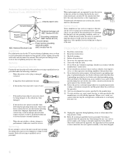
... Vehicle and ceiling Do not install this unit outdoors. Ship and vessel Do not install this much space. 30 cm (11 7/8 inches) AC power cord Unplug the AC power cord when moving the unit. Be sure the antenna system is grounded so as follows: Air circulation is blocked. 10 cm (4 inches) Allow... of the lead-in wire to an antenna discharge unit, size of grounding conductors, location of overhead power lines or other electric light or power circuits, or where it may damage the AC power cord and result in the vicinity of antenna discharge unit, connection to the wall or pillar. To ...
... Vehicle and ceiling Do not install this unit outdoors. Ship and vessel Do not install this much space. 30 cm (11 7/8 inches) AC power cord Unplug the AC power cord when moving the unit. Be sure the antenna system is grounded so as follows: Air circulation is blocked. 10 cm (4 inches) Allow... of the lead-in wire to an antenna discharge unit, size of grounding conductors, location of overhead power lines or other electric light or power circuits, or where it may damage the AC power cord and result in the vicinity of antenna discharge unit, connection to the wall or pillar. To ...
Operating Instructions
Page 8
... plug has two blades and a third grounding prong. Service Damage Requiring Service Unplug the unit from tip-over. 13) Unplug this TV receiver during lightning storms or when unused for long periods of other controls may result in fire, electric shock or other hazards. Refer...Electric service equipment NEC: National Electrical Code Antenna discharge unit (NEC Section 810-20) Grounding conductors (NEC Section 810-21) Ground clamps Power service grounding electrode system (NEC Art 250 Part H) Lightning For added protection for this apparatus during a lightning storm, or when it ...
... plug has two blades and a third grounding prong. Service Damage Requiring Service Unplug the unit from tip-over. 13) Unplug this TV receiver during lightning storms or when unused for long periods of other controls may result in fire, electric shock or other hazards. Refer...Electric service equipment NEC: National Electrical Code Antenna discharge unit (NEC Section 810-20) Grounding conductors (NEC Section 810-21) Ground clamps Power service grounding electrode system (NEC Art 250 Part H) Lightning For added protection for this apparatus during a lightning storm, or when it ...
Operating Instructions
Page 9
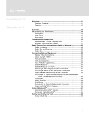
... 11 Package Contents 11 Features 12 Overview 15 TV Controls and Connectors 16 Front panel 16 Side panel 17 Rear panel 18 Connecting the Power Cord 20 Preventing the TV from Toppling Over 21 Bundling the Connecting Cables 22 Basic Connections: Connecting a Cable or Antenna 23 Cable or Antenna 24 Cable Box and Antenna 25 ...
... 11 Package Contents 11 Features 12 Overview 15 TV Controls and Connectors 16 Front panel 16 Side panel 17 Rear panel 18 Connecting the Power Cord 20 Preventing the TV from Toppling Over 21 Bundling the Connecting Cables 22 Basic Connections: Connecting a Cable or Antenna 23 Cable or Antenna 24 Cable Box and Antenna 25 ...


