
Operating Guide
Page 6
... damage the hard disk drive of your camcorder • The hard disk of the camcorder may not be recognized, or recording or playback may not be stopped. In addition to the above, when you dispose of the camcorder, it is recommended that you do so, your data. In this case, an indicator appears in the viewfinder (HDR-SR7/SR8...
... damage the hard disk drive of your camcorder • The hard disk of the camcorder may not be recognized, or recording or playback may not be stopped. In addition to the above, when you dispose of the camcorder, it is recommended that you do so, your data. In this case, an indicator appears in the viewfinder (HDR-SR7/SR8...
Operating Guide
Page 14
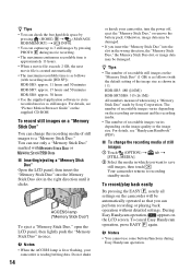
... the "Memory Stick Duo," or remove the battery pack. Do not shake 14 or knock your camcorder is as shown in the right direction until it clicks. HDR-SR5: 480 ([4.0M]) HDR-SR7/SR8: 315 ([6.1M]) All numbers measured when using a "Memory Stick Duo" made by ...hard disk space by pressing (HOME) B t (MANAGE HDD/MEMORY) t [ INFO]. • You can capture up to 3 still images by Sony Corporation. To cancel Easy Handycam operation, press EASY F again. For details, see "Handycam Handbook" (PDF). x To change the recording media of recordable images varies depending on the camcorder...
... the "Memory Stick Duo," or remove the battery pack. Do not shake 14 or knock your camcorder is as shown in the right direction until it clicks. HDR-SR5: 480 ([4.0M]) HDR-SR7/SR8: 315 ([6.1M]) All numbers measured when using a "Memory Stick Duo" made by ...hard disk space by pressing (HOME) B t (MANAGE HDD/MEMORY) t [ INFO]. • You can capture up to 3 still images by Sony Corporation. To cancel Easy Handycam operation, press EASY F again. For details, see "Handycam Handbook" (PDF). x To change the recording media of recordable images varies depending on the camcorder...
Operating Guide
Page 16
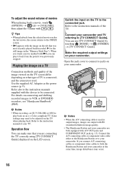
...adjust the volume with / . Connect the A/V connecting cable or component video cable either to the Handycam Station or to VCR or DVD/HDD recorders, see "Handycam Handbook" (PDF). When you connect A/V connecting cables or component video cables to be adjusted on connecting and dubbing ...9). Refer to output images, images are output with SD (standard definition) image quality. • The Handycam Station and your camcorder are connecting the TV correctly using [TV CONNECT Guide] displayed on your camcorder at the same time, image disturbance may need to the connected jack...
...adjust the volume with / . Connect the A/V connecting cable or component video cable either to the Handycam Station or to VCR or DVD/HDD recorders, see "Handycam Handbook" (PDF). When you connect A/V connecting cables or component video cables to be adjusted on connecting and dubbing ...9). Refer to output images, images are output with SD (standard definition) image quality. • The Handycam Station and your camcorder are connecting the TV correctly using [TV CONNECT Guide] displayed on your camcorder at the same time, image disturbance may need to the connected jack...

Operating Guide
Page 23
Items of your camcorder at the time. • Some items appear without a tab. • The (OPTION) MENU cannot be used during Easy Handycam operation (p. 14). b Notes • When the ... by date], [ ADD by date], [ ERASE], [ ERASE], [ ERASE ALL], [ ERASE ALL], [ MOVE], [ MOVE] PRINT [ PRINT], [ PRINT] COMPUTER [ COMPUTER], [ COMPUTER], [DISC BURN] TV CONNECT Guide*1 (MANAGE HDD/MEMORY) category FORMAT*1 FORMAT*1 INFO REPAIR IMG.DB F. (SETTINGS) category MOVIE SETTINGS [ / REC SET]*1, [ REC MODE], [ REC MODE], [AE SHIFT]*3, [WB SHIFT]*3, [NIGHTSHOT LIGHT], [WIDE...
Items of your camcorder at the time. • Some items appear without a tab. • The (OPTION) MENU cannot be used during Easy Handycam operation (p. 14). b Notes • When the ... by date], [ ADD by date], [ ERASE], [ ERASE], [ ERASE ALL], [ ERASE ALL], [ MOVE], [ MOVE] PRINT [ PRINT], [ PRINT] COMPUTER [ COMPUTER], [ COMPUTER], [DISC BURN] TV CONNECT Guide*1 (MANAGE HDD/MEMORY) category FORMAT*1 FORMAT*1 INFO REPAIR IMG.DB F. (SETTINGS) category MOVIE SETTINGS [ / REC SET]*1, [ REC MODE], [ REC MODE], [AE SHIFT]*3, [WB SHIFT]*3, [NIGHTSHOT LIGHT], [WIDE...
Operating Guide
Page 25
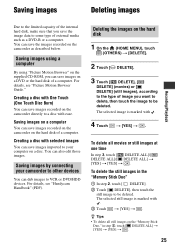
Creating a disc with One Touch (One Touch Disc Burn) You can save images recorded on the camcorder directly to a disc with . 4 Touch t [YES] t . Saving images by connecting your computer on the hard disk 1 On the (HOME MENU), touch (OTHERS) t [DELETE]. 2 Touch [ DELETE]. 3 Touch [ DELETE], [ DELETE] (movies)... ALL]/[ DELETE ALL] t [YES] t [YES] t . For details, see "Handycam Handbook" (PDF). You can dub images to VCR or DVD/HDD devices. Deleting the images on a disc. Saving images on a computer You can save images on the "Memory Stick Duo," in the "Memory Stick Duo"...
Creating a disc with One Touch (One Touch Disc Burn) You can save images recorded on the camcorder directly to a disc with . 4 Touch t [YES] t . Saving images by connecting your computer on the hard disk 1 On the (HOME MENU), touch (OTHERS) t [DELETE]. 2 Touch [ DELETE]. 3 Touch [ DELETE], [ DELETE] (movies)... ALL]/[ DELETE ALL] t [YES] t [YES] t . For details, see "Handycam Handbook" (PDF). You can dub images to VCR or DVD/HDD devices. Deleting the images on a disc. Saving images on a computer You can save images on the "Memory Stick Duo," in the "Memory Stick Duo"...

Service Manual
Page 5
Ver. 1.1 2007.06 Model information table Model SR5 Destination US, CND, KR, E, JE Color system HDD Viewfinder HP jack/MIC jack CM board BL board NTSC 40G CM-076 SR5C US NTSC 100G CM-076 SR5E ... HK, AUS, E, JE PAL 40G SR7 US, CND, KR, E, JE, J NTSC 60G CM-076 CM-077 BL-013 Model Destination Color system HDD Viewfinder HP jack/MIC jack CM board BL board SR7E AEP, UK, CH, HK, AUS, E, JE PAL 60G SR8 US, CND, KR, E, JE... HK : Hong Kong model J : Japanese model JE : Tourist model KR : Korea model MX : Mexican model NE : North European model HDR-SR5/SR5C/SR5E/SR7/SR7E/SR8/SR8E_L2 - 5 -
Ver. 1.1 2007.06 Model information table Model SR5 Destination US, CND, KR, E, JE Color system HDD Viewfinder HP jack/MIC jack CM board BL board NTSC 40G CM-076 SR5C US NTSC 100G CM-076 SR5E ... HK, AUS, E, JE PAL 40G SR7 US, CND, KR, E, JE, J NTSC 60G CM-076 CM-077 BL-013 Model Destination Color system HDD Viewfinder HP jack/MIC jack CM board BL board SR7E AEP, UK, CH, HK, AUS, E, JE PAL 60G SR8 US, CND, KR, E, JE... HK : Hong Kong model J : Japanese model JE : Tourist model KR : Korea model MX : Mexican model NE : North European model HDR-SR5/SR5C/SR5E/SR7/SR7E/SR8/SR8E_L2 - 5 -

Service Manual
Page 28
...OVERALL SECTION-1 - Cabinet (R) Section - OVERALL SECTION-3 - VC-504 Board - LCD - Flash Unit (FL25500) HDR-SR5/SR5C/SR5E/SR7/SR7E/SR8/SR8E_L2 2-2 OVERALL SECTION-2 (SR5/SR5C/SR5E) - HDD - LCD Panel Block 2-2-5. Lens Section - CABINET (L) SECTION-2 - LD-228 Board - Bottom Cabinet Block 2-2-1. ...-324 Board 2-2-4. Main frame section 2-2-7. Lens Barrier Unit 2-2-11. LENS SECTION (SR5/SR5C/SR5E) - 2-1. Cabinet (G) Assy - IDENTIFYING PARTS Cabinet (G) Assy Control Switch Block (PS25500) HDD SR7/SR7E/ SR8/SR8E EVF Block ⋅ BL-013 Board Cabinet (L) Section ...
...OVERALL SECTION-1 - Cabinet (R) Section - OVERALL SECTION-3 - VC-504 Board - LCD - Flash Unit (FL25500) HDR-SR5/SR5C/SR5E/SR7/SR7E/SR8/SR8E_L2 2-2 OVERALL SECTION-2 (SR5/SR5C/SR5E) - HDD - LCD Panel Block 2-2-5. Lens Section - CABINET (L) SECTION-2 - LD-228 Board - Bottom Cabinet Block 2-2-1. ...-324 Board 2-2-4. Main frame section 2-2-7. Lens Barrier Unit 2-2-11. LENS SECTION (SR5/SR5C/SR5E) - 2-1. Cabinet (G) Assy - IDENTIFYING PARTS Cabinet (G) Assy Control Switch Block (PS25500) HDD SR7/SR7E/ SR8/SR8E EVF Block ⋅ BL-013 Board Cabinet (L) Section ...

Service Manual
Page 29
DISASSEMBLY 2-2-1. OVERALL SECTION-1 Follow the disassembly in the numerical order given. 1 Cabinet (G) Assy (1-1 to 1-6) 2 HDD (2-1 to 2-3) 3 Bottom Cabinet Block (3-1) HELP EXPLODED VIEW HARDWARE LIST 1-2 (#2) 1 Cabinet (G) Assy 1-4 (#2) 1-1 (Slide the Jack Cover(G)) 2-1 1-6 (Claw) Overall Section-2 (See Page 2-5 (SR5/SR5C/SR5E)) (See Page 2-4 (SR7/SR7E/SR8/SR8E)) 2 HDD (Note) SR5/SR5C/SR5E without EVF is same the removing procedure. 2-3 2-2 HELP 1-3 (Open the Jack Cover (HDMI)) 1-5 (#2) 3 Bottom Cabinet Block HDR-SR5/SR5C/SR5E/SR7/SR7E/SR8/SR8E_L2 3-1 (#2) 2-3 2-2.
DISASSEMBLY 2-2-1. OVERALL SECTION-1 Follow the disassembly in the numerical order given. 1 Cabinet (G) Assy (1-1 to 1-6) 2 HDD (2-1 to 2-3) 3 Bottom Cabinet Block (3-1) HELP EXPLODED VIEW HARDWARE LIST 1-2 (#2) 1 Cabinet (G) Assy 1-4 (#2) 1-1 (Slide the Jack Cover(G)) 2-1 1-6 (Claw) Overall Section-2 (See Page 2-5 (SR5/SR5C/SR5E)) (See Page 2-4 (SR7/SR7E/SR8/SR8E)) 2 HDD (Note) SR5/SR5C/SR5E without EVF is same the removing procedure. 2-3 2-2 HELP 1-3 (Open the Jack Cover (HDMI)) 1-5 (#2) 3 Bottom Cabinet Block HDR-SR5/SR5C/SR5E/SR7/SR7E/SR8/SR8E_L2 3-1 (#2) 2-3 2-2.

Service Manual
Page 56
... DIAGRAMS Link CK-183 BOARD (CONTROL SWITCH) PD-324 BOARD (LCD DRIVE) JK-342 BOARD (JACK) ST-175 BOARD (FLASH DRIVE) MS-374 BOARD (MS CONNECTOR) BL-013 BOARD : SR7/SR7E/SR8/SR8E (EVF, EVF BACKLIGHT) FP-515 FLEXIBLE BOARD (HDD CONNECTION) FP-537 FLEXIBLE BOARD (CK-PD CONNECTION) FP-546 FLEXIBLE BOARD.../SR7E/SR8/SR8E CONTROL SWITCH BLOCK (PS25500) CONTROL SWITCH BLOCK (SB25500) CONTROL KEY BLOCK (SB22200) FLASH UNIT (FL25500) COMMON NOTE FOR SCHEMATIC DIAGRAMS SIGNAL LOCATION HDR-SR5/SR5C/SR5E/SR7/SR7E/SR8/SR8E_L2
... DIAGRAMS Link CK-183 BOARD (CONTROL SWITCH) PD-324 BOARD (LCD DRIVE) JK-342 BOARD (JACK) ST-175 BOARD (FLASH DRIVE) MS-374 BOARD (MS CONNECTOR) BL-013 BOARD : SR7/SR7E/SR8/SR8E (EVF, EVF BACKLIGHT) FP-515 FLEXIBLE BOARD (HDD CONNECTION) FP-537 FLEXIBLE BOARD (CK-PD CONNECTION) FP-546 FLEXIBLE BOARD.../SR7E/SR8/SR8E CONTROL SWITCH BLOCK (PS25500) CONTROL SWITCH BLOCK (SB25500) CONTROL KEY BLOCK (SB22200) FLASH UNIT (FL25500) COMMON NOTE FOR SCHEMATIC DIAGRAMS SIGNAL LOCATION HDR-SR5/SR5C/SR5E/SR7/SR7E/SR8/SR8E_L2

Service Manual
Page 66
E F FP-515 FLEXIBLE BOARD HDD CONNECTION FP-515 VC-504 (1/21) CN1004 PAGE 4-7 of LEVEL 3 4-38 E F 08 HDR-SR5/SR5C/SR5E/SR7/SR7E/SR8/SR8E_L2 Pin 1 LND001 3 LND003 4 LND004 LND005 LND006 LND007 LND008 LND009 LND010 LND011 LND012 LND013 LND014 LND015 LND016 LND017 LND018 LND019 ... LND076 LND075 LND074 LND073 LND072 LND071 LND070 LND069 LND068 LND067 LND066 LND065 LND064 LND063 LND062 LND061 LND060 LND059 LND058 LND057 LND056 LND055 LND054 5 LND053 4 LND052 3 B B HARD DISK DRIVE A A 8 7 6 5 4 3 2 1 Ver. 1.1 2007.06
E F FP-515 FLEXIBLE BOARD HDD CONNECTION FP-515 VC-504 (1/21) CN1004 PAGE 4-7 of LEVEL 3 4-38 E F 08 HDR-SR5/SR5C/SR5E/SR7/SR7E/SR8/SR8E_L2 Pin 1 LND001 3 LND003 4 LND004 LND005 LND006 LND007 LND008 LND009 LND010 LND011 LND012 LND013 LND014 LND015 LND016 LND017 LND018 LND019 ... LND076 LND075 LND074 LND073 LND072 LND071 LND070 LND069 LND068 LND067 LND066 LND065 LND064 LND063 LND062 LND061 LND060 LND059 LND058 LND057 LND056 LND055 LND054 5 LND053 4 LND052 3 B B HARD DISK DRIVE A A 8 7 6 5 4 3 2 1 Ver. 1.1 2007.06

Service Manual
Page 91
...-60GB) (SR7/SR7E) Ref. Description 1-797-808-11 HDD (MK4009GAL-40GB) (SR5/SR5E) 1-797-867-11 HDD (MK1011GAH-100GB) (SR5C/SR8/SR8E) (Note 1) CABINET (G) ASSY 2-635-562-31 SCREW (M1.7) (Black) 3-078-890-01 SCREW, TAPPING (Silver) 2-599-475-11 SCREW (M1.7) (Silver) HDR-SR5/SR5C/SR5E/SR7/SR7E/SR8/SR8E_L2 5-2 Note 1 G 1-13 G Note 2 : Be sure...
...-60GB) (SR7/SR7E) Ref. Description 1-797-808-11 HDD (MK4009GAL-40GB) (SR5/SR5E) 1-797-867-11 HDD (MK1011GAH-100GB) (SR5C/SR8/SR8E) (Note 1) CABINET (G) ASSY 2-635-562-31 SCREW (M1.7) (Black) 3-078-890-01 SCREW, TAPPING (Silver) 2-599-475-11 SCREW (M1.7) (Silver) HDR-SR5/SR5C/SR5E/SR7/SR7E/SR8/SR8E_L2 5-2 Note 1 G 1-13 G Note 2 : Be sure...

Service Manual
Page 110
... SR7/SR7E/SR8/SR8E J7222 203 #3 #12 #12 204 HDR-SR5/SR5C/SR5E/SR7/SR7E/SR8/SR8E_L2 9-852-202-81 Sony EMCS Co. 2007J0800-1 ©2007.10 Published by Kohda TEC REPAIR PARTS LIST 5-1. HDR-SR5/SR5C/SR5E/SR7/SR7E/SR8/SR8E RMT-835 SERVICE MANUAL Ver....-1 File this supplement with the service manual previously issued. (DI07-142) • Change of Repair Parts List 5. Description 5-2 8 1-797-659-11 HDD (MK6008GAH-60GB) (SR7/SR7E) : Points changed portion After changed 5-1-1. Part No. EXPLODED VIEWS Page Before changed 5-1-1. OVERALL SECTION-1 Ref. CABINET (L) ...
... SR7/SR7E/SR8/SR8E J7222 203 #3 #12 #12 204 HDR-SR5/SR5C/SR5E/SR7/SR7E/SR8/SR8E_L2 9-852-202-81 Sony EMCS Co. 2007J0800-1 ©2007.10 Published by Kohda TEC REPAIR PARTS LIST 5-1. HDR-SR5/SR5C/SR5E/SR7/SR7E/SR8/SR8E RMT-835 SERVICE MANUAL Ver....-1 File this supplement with the service manual previously issued. (DI07-142) • Change of Repair Parts List 5. Description 5-2 8 1-797-659-11 HDD (MK6008GAH-60GB) (SR7/SR7E) : Points changed portion After changed 5-1-1. Part No. EXPLODED VIEWS Page Before changed 5-1-1. OVERALL SECTION-1 Ref. CABINET (L) ...


