

Operating Guide
Page 35
...disassembling, modifying, physical shock, or impact such as under direct sunlight, near heaters or in a car parked in the sun. On a sandy beach or anywhere dusty. If sand or dust gets in your camcorder...where the LCD screen, the viewfinder (HDR-SR7/SR8), or the lens may cause damage. • If your camcorder is soiled, clean the camcorder body with a soft cloth lightly moistened...x When not using your camcorder for example, and operate it . This is not a malfunction. • While using your camcorder. • Do not wrap your local authorized Sony service facility. - Use cleaning...
...disassembling, modifying, physical shock, or impact such as under direct sunlight, near heaters or in a car parked in the sun. On a sandy beach or anywhere dusty. If sand or dust gets in your camcorder...where the LCD screen, the viewfinder (HDR-SR7/SR8), or the lens may cause damage. • If your camcorder is soiled, clean the camcorder body with a soft cloth lightly moistened...x When not using your camcorder for example, and operate it . This is not a malfunction. • While using your camcorder. • Do not wrap your local authorized Sony service facility. - Use cleaning...
Operating Guide
Page 36
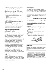
... Battery may not function properly. Do not recharge, disassemble or dispose of in about 3 months if you are fingerprints on the tab, inset your fingernail into the Remote Commander until it with a Sony CR2025 lithium battery. On charging the pre-installed rechargeable battery Your camcorder has a pre-installed rechargeable battery to retain the...
... Battery may not function properly. Do not recharge, disassemble or dispose of in about 3 months if you are fingerprints on the tab, inset your fingernail into the Remote Commander until it with a Sony CR2025 lithium battery. On charging the pre-installed rechargeable battery Your camcorder has a pre-installed rechargeable battery to retain the...

Service Manual
Page 1
... que par une pièce portant le numéro spécifié. DIGITAL VIDEO CAMERA RECORDER HDR-SR5/SR5C/SR5E/SR7/SR7E/SR8/SR8E_L2 9-852-202-32 Sony EMCS Co. 2007K0800-1 © 2007.11 Published by mark 0 or dotted line with mark 0 are critical...0 sont critiques pour la sécurité. Photo: HDR-SR5 2 LEVEL US Model Canadian Model AEP Model UK Model E Model Australian Model Hong Kong Model Chinese Model Korea Model Tourist Model Japanese Model Link SPECIFICATIONS DISASSEMBLY SCHEMATIC DIAGRAMS MODEL INFORMATION TABLE BLOCK DIAGRAMS PRINTED WIRING BOARDS SERVICE...
... que par une pièce portant le numéro spécifié. DIGITAL VIDEO CAMERA RECORDER HDR-SR5/SR5C/SR5E/SR7/SR7E/SR8/SR8E_L2 9-852-202-32 Sony EMCS Co. 2007K0800-1 © 2007.11 Published by mark 0 or dotted line with mark 0 are critical...0 sont critiques pour la sécurité. Photo: HDR-SR5 2 LEVEL US Model Canadian Model AEP Model UK Model E Model Australian Model Hong Kong Model Chinese Model Korea Model Tourist Model Japanese Model Link SPECIFICATIONS DISASSEMBLY SCHEMATIC DIAGRAMS MODEL INFORMATION TABLE BLOCK DIAGRAMS PRINTED WIRING BOARDS SERVICE...
Service Manual
Page 27
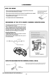
...There is a danger of electric shock by the charged voltage which comes off at the terminal. HDR-SR5/SR5C/SR5E/SR7/SR7E/SR8/SR8E_L2 2-1 2. Therefore, the remaining voltage must be left inside) DISCHARGING...8226; When installing a connector, don't press down at wire of 1 kΩ /1 W (1-215-869-11). DISASSEMBLY NOTE FOR REPAIR • Make sure that a wire is charged up to each end of a resistor of connector...gilded flexible board. The electric shock is caused by this high voltage when the capacitor is snapped. • Do not apply excessive load to prevent electrical shock....
...There is a danger of electric shock by the charged voltage which comes off at the terminal. HDR-SR5/SR5C/SR5E/SR7/SR7E/SR8/SR8E_L2 2-1 2. Therefore, the remaining voltage must be left inside) DISCHARGING...8226; When installing a connector, don't press down at wire of 1 kΩ /1 W (1-215-869-11). DISASSEMBLY NOTE FOR REPAIR • Make sure that a wire is charged up to each end of a resistor of connector...gilded flexible board. The electric shock is caused by this high voltage when the capacitor is snapped. • Do not apply excessive load to prevent electrical shock....

Service Manual
Page 28
...8901; VC-504 Board ⋅ JK-342 Board BT Panel Block ⋅ MS-374 Board Lens Section Lens Section (SR7/SR7E/SR8/SR8E) (SR5/SR5C/SR5E) ⋅ ST-175 Board ⋅ ST-175 Board ⋅ LD-228 Board ⋅ LD-228 Board ⋅ CM-077...SR7E/SR8/SR8E) Cabinet (R) Section ⋅ CK-183 Board ⋅ PD-324 Board 2-2-4. VC-504 Board - Hinge Block - Flash Unit (FL25500) HDR-SR5/SR5C/SR5E/SR7/SR7E/SR8/SR8E_L2 2-2 DISASSEMBLY FLOW - CABINET (L) SECTION-1 - ST-175 Board - 2-1. Bottom Cabinet Block 2-2-1. Cabinet (G) Assy - OVERALL SECTION-2 (SR7/SR7E/SR8/SR8E) 2-2-3. ...
...8901; VC-504 Board ⋅ JK-342 Board BT Panel Block ⋅ MS-374 Board Lens Section Lens Section (SR7/SR7E/SR8/SR8E) (SR5/SR5C/SR5E) ⋅ ST-175 Board ⋅ ST-175 Board ⋅ LD-228 Board ⋅ LD-228 Board ⋅ CM-077...SR7E/SR8/SR8E) Cabinet (R) Section ⋅ CK-183 Board ⋅ PD-324 Board 2-2-4. VC-504 Board - Hinge Block - Flash Unit (FL25500) HDR-SR5/SR5C/SR5E/SR7/SR7E/SR8/SR8E_L2 2-2 DISASSEMBLY FLOW - CABINET (L) SECTION-1 - ST-175 Board - 2-1. Bottom Cabinet Block 2-2-1. Cabinet (G) Assy - OVERALL SECTION-2 (SR7/SR7E/SR8/SR8E) 2-2-3. ...

Service Manual
Page 29
2-2. OVERALL SECTION-1 Follow the disassembly in the numerical order given. 1 Cabinet (G) Assy (1-1 to 1-6) 2 HDD (2-1 to 2-3) 3 Bottom Cabinet Block (3-1) HELP EXPLODED VIEW HARDWARE LIST 1-2 (#2) 1 Cabinet (G) Assy 1-4 (#2) 1-1 (Slide the Jack Cover(G)) 2-1 1-6 (Claw) Overall Section-2 (See Page 2-5 (SR5/SR5C/SR5E)) (See Page 2-4 (SR7/SR7E/SR8/SR8E)) 2 HDD (Note) SR5/SR5C/SR5E without EVF is same the removing procedure. 2-3 2-2 HELP 1-3 (Open the Jack Cover (HDMI)) 1-5 (#2) 3 Bottom Cabinet Block HDR-SR5/SR5C/SR5E/SR7/SR7E/SR8/SR8E_L2 3-1 (#2) 2-3 DISASSEMBLY 2-2-1.
2-2. OVERALL SECTION-1 Follow the disassembly in the numerical order given. 1 Cabinet (G) Assy (1-1 to 1-6) 2 HDD (2-1 to 2-3) 3 Bottom Cabinet Block (3-1) HELP EXPLODED VIEW HARDWARE LIST 1-2 (#2) 1 Cabinet (G) Assy 1-4 (#2) 1-1 (Slide the Jack Cover(G)) 2-1 1-6 (Claw) Overall Section-2 (See Page 2-5 (SR5/SR5C/SR5E)) (See Page 2-4 (SR7/SR7E/SR8/SR8E)) 2 HDD (Note) SR5/SR5C/SR5E without EVF is same the removing procedure. 2-3 2-2 HELP 1-3 (Open the Jack Cover (HDMI)) 1-5 (#2) 3 Bottom Cabinet Block HDR-SR5/SR5C/SR5E/SR7/SR7E/SR8/SR8E_L2 3-1 (#2) 2-3 DISASSEMBLY 2-2-1.

Service Manual
Page 30
... LCD Panel) 2-1 2-2 (#2) R:1 kΩ/1 W (Part code: 1-215-869-11) HDR-SR5/SR5C/SR5E/SR7/SR7E/SR8/SR8E_L2 2-4 To avoid the spark with the metal plate, wrap the short jig with the short jig about 10 seconds. OVERALL SECTION-2 (SR7/SR7E/SR8/SR8E) Follow the disassembly in the numerical order given. 1 Cabinet (T(255)) (1-1 to 1-6) 2 Cabinet...
... LCD Panel) 2-1 2-2 (#2) R:1 kΩ/1 W (Part code: 1-215-869-11) HDR-SR5/SR5C/SR5E/SR7/SR7E/SR8/SR8E_L2 2-4 To avoid the spark with the metal plate, wrap the short jig with the short jig about 10 seconds. OVERALL SECTION-2 (SR7/SR7E/SR8/SR8E) Follow the disassembly in the numerical order given. 1 Cabinet (T(255)) (1-1 to 1-6) 2 Cabinet...

Service Manual
Page 31
...(SR5/SR5C/SR5E) Follow the disassembly in the numerical order given. 1 Cabinet (T(255)) Assy (1-1 to 1-5) 2 Cabinet (R) Section (2-1 to 2-3) 3 BT Panel Block (3-1) 1-1 1-2 (#2) (Open the Shoe Cover) EXPLODED VIEW HARDWARE LIST 1 Cabinet (T(255)) Assy 1-3 (#2) Note: High-...voltage cautions Discharging the Capacitor Short-circuit between the two points with the insulation tape. C5206 (Charging Capacitor) ST-175 Board 3 BT Panel Block 3-1(#2) 2 Cabinet (R) Section (See Page 2-12) 1-5 (#2) 2-3 (#2) 1-4 (Open the LCD Panel) 2-1 2-2 (#2) R:1 kΩ/1 W (Part code: 1-215-869-11) HDR-SR5...
...(SR5/SR5C/SR5E) Follow the disassembly in the numerical order given. 1 Cabinet (T(255)) Assy (1-1 to 1-5) 2 Cabinet (R) Section (2-1 to 2-3) 3 BT Panel Block (3-1) 1-1 1-2 (#2) (Open the Shoe Cover) EXPLODED VIEW HARDWARE LIST 1 Cabinet (T(255)) Assy 1-3 (#2) Note: High-...voltage cautions Discharging the Capacitor Short-circuit between the two points with the insulation tape. C5206 (Charging Capacitor) ST-175 Board 3 BT Panel Block 3-1(#2) 2 Cabinet (R) Section (See Page 2-12) 1-5 (#2) 2-3 (#2) 1-4 (Open the LCD Panel) 2-1 2-2 (#2) R:1 kΩ/1 W (Part code: 1-215-869-11) HDR-SR5...

Service Manual
Page 32
OVERALL SECTION-3 Follow the disassembly in the numerical order given. 1 Control Switch Block (PS25500) (1-1 to 1-2) 2 Cabinet (F) Block (2-1 to 2-2) EXPLODED VIEW HARDWARE LIST 1 Control Switch Block (PS25500) 1-1 (#12) 1-2 (#2) 2-1 (#14) SR5/SR5C/SR5E Cabinet (L) Section-1 (See Page 2-7) Refer to page 2-1 "Note for disconnection the harness (coaxial cable) " 2 Cabinet (F) 2-2 (#2) Block (See Page 2-9) SR7/SR7E/SR8/SR8E 2 Cabinet (F) 2-2 (#2) Block (See Page 2-9) HDR-SR5/SR5C/SR5E/SR7/SR7E/SR8/SR8E_L2 2-6 2-2-4.
OVERALL SECTION-3 Follow the disassembly in the numerical order given. 1 Control Switch Block (PS25500) (1-1 to 1-2) 2 Cabinet (F) Block (2-1 to 2-2) EXPLODED VIEW HARDWARE LIST 1 Control Switch Block (PS25500) 1-1 (#12) 1-2 (#2) 2-1 (#14) SR5/SR5C/SR5E Cabinet (L) Section-1 (See Page 2-7) Refer to page 2-1 "Note for disconnection the harness (coaxial cable) " 2 Cabinet (F) 2-2 (#2) Block (See Page 2-9) SR7/SR7E/SR8/SR8E 2 Cabinet (F) 2-2 (#2) Block (See Page 2-9) HDR-SR5/SR5C/SR5E/SR7/SR7E/SR8/SR8E_L2 2-6 2-2-4.

Service Manual
Page 33
2-2-5. CABINET (L) SECTION-1 Follow the disassembly in the numerical order given. 1 VC-504 Board (1-1 to 1-5) 2 Main Frame Section (2-1 to 2-4) EXPLODED VIEW HARDWARE LIST 1-4 2-2(#3) 1-3 (Peel off the Flexible Board) Cabinet (L) Section-2 (See Page 2-8) 1-5 1-2 (#3) 2-1(#14) (SR7/SR7E/ SR8/SR8E) 2-3 (#12) 2-4 (#12) VC-504 2 Main Frame Section 1 VC-504 Board 1-1 (#3) HDR-SR5/SR5C/SR5E/SR7/SR7E/SR8/SR8E_L2 2-7
2-2-5. CABINET (L) SECTION-1 Follow the disassembly in the numerical order given. 1 VC-504 Board (1-1 to 1-5) 2 Main Frame Section (2-1 to 2-4) EXPLODED VIEW HARDWARE LIST 1-4 2-2(#3) 1-3 (Peel off the Flexible Board) Cabinet (L) Section-2 (See Page 2-8) 1-5 1-2 (#3) 2-1(#14) (SR7/SR7E/ SR8/SR8E) 2-3 (#12) 2-4 (#12) VC-504 2 Main Frame Section 1 VC-504 Board 1-1 (#3) HDR-SR5/SR5C/SR5E/SR7/SR7E/SR8/SR8E_L2 2-7

Service Manual
Page 34
CABINET (L) SECTION-2 Follow the disassembly in the numerical order given. 1 JK-342 Board (1-1 to 1-5) SR7/SR7E/ SR8/SR8E EXPLODED VIEW HARDWARE LIST 1 JK-342 Board 1-2 1-3 (#2) 1-4 1-5 1-1(#12) SR7/SR7E/SR8/SR8E HDR-SR5/SR5C/SR5E/SR7/SR7E/SR8/SR8E_L2 2-8 2-2-6.
CABINET (L) SECTION-2 Follow the disassembly in the numerical order given. 1 JK-342 Board (1-1 to 1-5) SR7/SR7E/ SR8/SR8E EXPLODED VIEW HARDWARE LIST 1 JK-342 Board 1-2 1-3 (#2) 1-4 1-5 1-1(#12) SR7/SR7E/SR8/SR8E HDR-SR5/SR5C/SR5E/SR7/SR7E/SR8/SR8E_L2 2-8 2-2-6.

Service Manual
Page 35
CABINET (F) BLOCK Follow the disassembly in the numerical order given. (SR5/SR5C/SR5E) 1 Lens Section (1-1 to 1-2) 2 Lens Barrier Unit (2-1 to 2-2) (SR7/SR7E/SR8/SR8E) 1 Lens Section (1-1 to 1-2) 2 Lens Barrier Unit (2-1 to 2-5) EXPLODED VIEW SR5/SR5C/SR5E 1 Lens Section (SR5/SR5C/SR5E) (See Page 2-11) HARDWARE LIST HELP 1-1 2 Lens Barrier Unit 2-1 2-2 (#8) 1-2(#12) SR7/SR7E/SR8/SR8E 2 Lens Barrier Unit HELP 2-1 2-4 (#8) 2-5 1 Lens Section (SR7/SR7E/SR8/SR8E) (See Page 2-10) 1-1(#14) 1-2 (#12) 2-3 HDR-SR5/SR5C/SR5E/SR7/SR7E/SR8/SR8E_L2 2-9 2-2(#8) 2-2-7.
CABINET (F) BLOCK Follow the disassembly in the numerical order given. (SR5/SR5C/SR5E) 1 Lens Section (1-1 to 1-2) 2 Lens Barrier Unit (2-1 to 2-2) (SR7/SR7E/SR8/SR8E) 1 Lens Section (1-1 to 1-2) 2 Lens Barrier Unit (2-1 to 2-5) EXPLODED VIEW SR5/SR5C/SR5E 1 Lens Section (SR5/SR5C/SR5E) (See Page 2-11) HARDWARE LIST HELP 1-1 2 Lens Barrier Unit 2-1 2-2 (#8) 1-2(#12) SR7/SR7E/SR8/SR8E 2 Lens Barrier Unit HELP 2-1 2-4 (#8) 2-5 1 Lens Section (SR7/SR7E/SR8/SR8E) (See Page 2-10) 1-1(#14) 1-2 (#12) 2-3 HDR-SR5/SR5C/SR5E/SR7/SR7E/SR8/SR8E_L2 2-9 2-2(#8) 2-2-7.

Service Manual
Page 36
LENS SECTION (SR7/SR7E/SR8/SR8E) Follow the disassembly in the numerical order given. 1 ST-175 Board (1-1 to 1-3) 2 LD-228 Board (2-1 to 2-4) 3 Flash Unit (FL25500) (3-1 to 3-8) EXPLODED VIEW HARDWARE LIST 1-1(#3) 3-1 (#14) 3-6 (Peel off the Flexible Board) 1-2 (Claw) 3 Flash Unit (FL25500) 3-2 (Claw) 3-7(#23) 3-3 3-4(#14) 3-5(Claw) 3-8 1 ST-175 Board ST-175 1-3 CM-077 2-2 2-1(Claw) LD-228 2-3(#3) 2-4 2 LD-228 Board Refer to page 2-1 "Note for disconnection the harness (coaxial cable) " Lens Block HDR-SR5/SR5C/SR5E/SR7/SR7E/SR8/SR8E_L2 2-10 2-2-8.
LENS SECTION (SR7/SR7E/SR8/SR8E) Follow the disassembly in the numerical order given. 1 ST-175 Board (1-1 to 1-3) 2 LD-228 Board (2-1 to 2-4) 3 Flash Unit (FL25500) (3-1 to 3-8) EXPLODED VIEW HARDWARE LIST 1-1(#3) 3-1 (#14) 3-6 (Peel off the Flexible Board) 1-2 (Claw) 3 Flash Unit (FL25500) 3-2 (Claw) 3-7(#23) 3-3 3-4(#14) 3-5(Claw) 3-8 1 ST-175 Board ST-175 1-3 CM-077 2-2 2-1(Claw) LD-228 2-3(#3) 2-4 2 LD-228 Board Refer to page 2-1 "Note for disconnection the harness (coaxial cable) " Lens Block HDR-SR5/SR5C/SR5E/SR7/SR7E/SR8/SR8E_L2 2-10 2-2-8.

Service Manual
Page 37
2-2-9. LENS SECTION (SR5/SR5C/SR5E) Follow the disassembly in the numerical order given. 1 ST-175 Board (1-1 to 1-3) 2 LD-228 Board (2-1 to 2-4) 3 Flash Unit (FL25500) (3-1 to 3-6) EXPLODED VIEW HARDWARE LIST 3-4 (Peel off the Flexible Board) 3-5 (#23) 3 Flash Unit (FL25500) 3-3 (Claw) 1-1(#3) 1-2 (Claw) 3-1 3-6 3-2(#14) 1 ST-175 Board ST-175 1-3 2-2 CM-076 2-4 2-1 (Claw) LD-228 2-3 (#3) 2 LD-228 Board Refer to page 2-1 "Note for disconnection the harness (coaxial cable) " Lens Block HDR-SR5/SR5C/SR5E/SR7/SR7E/SR8/SR8E_L2 2-11
2-2-9. LENS SECTION (SR5/SR5C/SR5E) Follow the disassembly in the numerical order given. 1 ST-175 Board (1-1 to 1-3) 2 LD-228 Board (2-1 to 2-4) 3 Flash Unit (FL25500) (3-1 to 3-6) EXPLODED VIEW HARDWARE LIST 3-4 (Peel off the Flexible Board) 3-5 (#23) 3 Flash Unit (FL25500) 3-3 (Claw) 1-1(#3) 1-2 (Claw) 3-1 3-6 3-2(#14) 1 ST-175 Board ST-175 1-3 2-2 CM-076 2-4 2-1 (Claw) LD-228 2-3 (#3) 2 LD-228 Board Refer to page 2-1 "Note for disconnection the harness (coaxial cable) " Lens Block HDR-SR5/SR5C/SR5E/SR7/SR7E/SR8/SR8E_L2 2-11

Service Manual
Page 38
CABINET (R) SECTION Follow the disassembly in the numerical order given. 1 Loud Speaker (1-1 to 1-2) 2 CK-183 Board (2-1 to 2-4) 3 LCD Panel Block (3-1 to 3-4) EXPLODED VIEW HARDWARE LIST 1 Loud Speaker 1-2 1-1 (#8) 3 LCD Panel Block (See Page 2-13) CK-183 3-4 3-3 2-1 (#12) (#8) 3-1 2-2 2-3 (#12) (#12) 2-4 2 CK-183 3-2 Board HDR-SR5/SR5C/SR5E/SR7/SR7E/SR8/SR8E_L2 2-12 2-2-10.
CABINET (R) SECTION Follow the disassembly in the numerical order given. 1 Loud Speaker (1-1 to 1-2) 2 CK-183 Board (2-1 to 2-4) 3 LCD Panel Block (3-1 to 3-4) EXPLODED VIEW HARDWARE LIST 1 Loud Speaker 1-2 1-1 (#8) 3 LCD Panel Block (See Page 2-13) CK-183 3-4 3-3 2-1 (#12) (#8) 3-1 2-2 2-3 (#12) (#12) 2-4 2 CK-183 3-2 Board HDR-SR5/SR5C/SR5E/SR7/SR7E/SR8/SR8E_L2 2-12 2-2-10.

Service Manual
Page 39
LCD PANEL BLOCK Follow the disassembly in the numerical order given. 1 Hinge Block (1-1 to 1-9) 2 LCD (2-1 to 2-2) 3 PD-324 Board (3-1 to 3-2) EXPLODED VIEW HARDWARE LIST HELP 1 Hinge Block HELP 1-8 1-4 (#12) E 1-5 1-9 (#2) 1-6 (Claw) A 1-7 2-1 (#8) 3 PD-324 Board 1-1 PD-324 (#2) A 3-1 B C D 1-3 1-2 (Claw) B C 2 LCD 3-2 E D 2-2 HDR-SR5/SR5C/SR5E/SR7/SR7E/SR8/SR8E_L2 2-13E 2-2-11.
LCD PANEL BLOCK Follow the disassembly in the numerical order given. 1 Hinge Block (1-1 to 1-9) 2 LCD (2-1 to 2-2) 3 PD-324 Board (3-1 to 3-2) EXPLODED VIEW HARDWARE LIST HELP 1 Hinge Block HELP 1-8 1-4 (#12) E 1-5 1-9 (#2) 1-6 (Claw) A 1-7 2-1 (#8) 3 PD-324 Board 1-1 PD-324 (#2) A 3-1 B C D 1-3 1-2 (Claw) B C 2 LCD 3-2 E D 2-2 HDR-SR5/SR5C/SR5E/SR7/SR7E/SR8/SR8E_L2 2-13E 2-2-11.

Service Manual
Page 91
... HDD (MK4009GAL-40GB) (SR5/SR5E) 1-797-867-11 HDD (MK1011GAH-100GB) (SR5C/SR8/SR8E) (Note 1) CABINET (G) ASSY 2-635-562-31 SCREW (M1.7) (Black) 3-078-890-01 SCREW, TAPPING (Silver) 2-599-475-11 SCREW (M1.7) (Silver) HDR-SR5/SR5C/SR5E/SR7/SR7E/SR8/SR8E_L2 5-2 OVERALL SECTION-1 ns: not supplied #2 9 (Note 1) 5. REPAIR PARTS LIST DISASSEMBLY HARDWARE LIST...
... HDD (MK4009GAL-40GB) (SR5/SR5E) 1-797-867-11 HDD (MK1011GAH-100GB) (SR5C/SR8/SR8E) (Note 1) CABINET (G) ASSY 2-635-562-31 SCREW (M1.7) (Black) 3-078-890-01 SCREW, TAPPING (Silver) 2-599-475-11 SCREW (M1.7) (Silver) HDR-SR5/SR5C/SR5E/SR7/SR7E/SR8/SR8E_L2 5-2 OVERALL SECTION-1 ns: not supplied #2 9 (Note 1) 5. REPAIR PARTS LIST DISASSEMBLY HARDWARE LIST...

Service Manual
Page 93
...-475-11 SCREW (M1.7) (Silver) HDR-SR5/SR5C/SR5E/SR7/SR7E/SR8/SR8E_L2 5-4 No. 101 101 101 Part No. No. #2 #12 #14 Part No. HARNESS (COAXIAL CABLE 2-1ページ "Note for disconnection the harness" when changing the harness. REPAIR PARTS LIST DISASSEMBLY HARDWARE LIST 101 #12 #2 #14 SR5/SR5C/SR5E Cabinet (L) Section-1 (See...
...-475-11 SCREW (M1.7) (Silver) HDR-SR5/SR5C/SR5E/SR7/SR7E/SR8/SR8E_L2 5-4 No. 101 101 101 Part No. No. #2 #12 #14 Part No. HARNESS (COAXIAL CABLE 2-1ページ "Note for disconnection the harness" when changing the harness. REPAIR PARTS LIST DISASSEMBLY HARDWARE LIST 101 #12 #2 #14 SR5/SR5C/SR5E Cabinet (L) Section-1 (See...

Service Manual
Page 94
...-01 SCREW, TAPPING (Silver) #12 3-080-204-21 SCREW, TAPPING, P2 (Black) #14 2-599-475-11 SCREW (M1.7) (Silver) HDR-SR5/SR5C/SR5E/SR7/SR7E/SR8/SR8E_L2 5-5 REPAIR PARTS LIST DISASSEMBLY HARDWARE LIST Cabinet (L) Section-2 (See Page 5-6) #14 #3 SR7/SR7E/ SR8/SR8E J7211 J7212 159 153 152 #3 #14 #14 #14... 154 155 162 161 #12 151 MIC901 ns ns SR5/SR5C/SR5E 158 #8 #12 156 157 VC-504 SR7/SR7E/ SR8/SR8E...
...-01 SCREW, TAPPING (Silver) #12 3-080-204-21 SCREW, TAPPING, P2 (Black) #14 2-599-475-11 SCREW (M1.7) (Silver) HDR-SR5/SR5C/SR5E/SR7/SR7E/SR8/SR8E_L2 5-5 REPAIR PARTS LIST DISASSEMBLY HARDWARE LIST Cabinet (L) Section-2 (See Page 5-6) #14 #3 SR7/SR7E/ SR8/SR8E J7211 J7212 159 153 152 #3 #14 #14 #14... 154 155 162 161 #12 151 MIC901 ns ns SR5/SR5C/SR5E 158 #8 #12 156 157 VC-504 SR7/SR7E/ SR8/SR8E...

Service Manual
Page 95
... P2 (Red) 3-080-204-21 SCREW, TAPPING, P2 (Black) 2-599-475-11 SCREW (M1.7) (Silver) HDR-SR5/SR5C/SR5E/SR7/SR7E/SR8/SR8E_L2 5-6 Description A-1274-042-A FP-729 FLEXIBLE BOARD, COMPLETE 3-213-057-01 FRAME ... JACK X-2178-739-1 CABINET (L (255)) ASSY (SR7/SR7E/SR8/SR8E) X-2178-740-1 CABINET (L (253)) ASSY (SR5/SR5C/SR5E) 2-664-928-31 BELT, GRIP 3-213-124-01 COVER (REMOTE), JACK 3-213-059-01 FRAME (R), JACK ...A-1274-034-A JK-342 BOARD, COMPLETE Ref. Ver. 1.1 2007.06 5-1-5. REPAIR PARTS LIST DISASSEMBLY HARDWARE LIST 213 211 212 #2 214 ns #12 209 215 210 ns 202 201 216 #3 219 ns...
... P2 (Red) 3-080-204-21 SCREW, TAPPING, P2 (Black) 2-599-475-11 SCREW (M1.7) (Silver) HDR-SR5/SR5C/SR5E/SR7/SR7E/SR8/SR8E_L2 5-6 Description A-1274-042-A FP-729 FLEXIBLE BOARD, COMPLETE 3-213-057-01 FRAME ... JACK X-2178-739-1 CABINET (L (255)) ASSY (SR7/SR7E/SR8/SR8E) X-2178-740-1 CABINET (L (253)) ASSY (SR5/SR5C/SR5E) 2-664-928-31 BELT, GRIP 3-213-124-01 COVER (REMOTE), JACK 3-213-059-01 FRAME (R), JACK ...A-1274-034-A JK-342 BOARD, COMPLETE Ref. Ver. 1.1 2007.06 5-1-5. REPAIR PARTS LIST DISASSEMBLY HARDWARE LIST 213 211 212 #2 214 ns #12 209 215 210 ns 202 201 216 #3 219 ns...

