

Service Manual
Page 5
...displayed and the slot is not set the "2-6, Memory Check". (See page 28) 4. J-2501-217-A) extension cable (DVD board-AMP board) (Part No. on this case, initialize Memory in the following procedures. NOTES ON LASER DIODE EMISSION CHECK The laser beam on clothing and the human body...J-8000-024-A) 5 extension cable (relay board-DVD board) (Part No. Between DAV-S400/S500/S800/C450/C700/C900 and DAV-S550/ S880/C770/C900, remote commander signal codes of the remote commander, and initial- SECTION 1 SERVICING NOTES HCD-C770/C990 Ver 1.6 NOTES ON HANDLING THE OPTICAL PICK-UP BLOCK OR...
...displayed and the slot is not set the "2-6, Memory Check". (See page 28) 4. J-2501-217-A) extension cable (DVD board-AMP board) (Part No. on this case, initialize Memory in the following procedures. NOTES ON LASER DIODE EMISSION CHECK The laser beam on clothing and the human body...J-8000-024-A) 5 extension cable (relay board-DVD board) (Part No. Between DAV-S400/S500/S800/C450/C700/C900 and DAV-S550/ S880/C770/C900, remote commander signal codes of the remote commander, and initial- SECTION 1 SERVICING NOTES HCD-C770/C990 Ver 1.6 NOTES ON HANDLING THE OPTICAL PICK-UP BLOCK OR...

Service Manual
Page 24
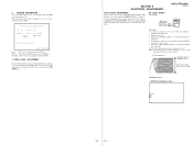
...-SL): PART No. Press the [POWER] button to DVD. 2. Drive Auto Adjustment 2. Video Level Adjustment Exit: POWER Key Model :DAV-Cxxx Revision...adjustment easily using the remote commander and monitor TV. HCD-C770/C990 Ver 1.4 SECTION 5 TEST MODE [GENERAL DESCRIPTION] ...): PART No. 4-999-032-01 TDV-540C (DVD-DL): PART No. J-2501-235-A Note: Do not use exiting test disc for the DVD system processor...Sampling Check 0-3-2. Detail Check 0-4. GP I/O Check 0-5. SD Bus Check 0-6. Video Check 0-7. Audio Check 0-2. Version 0-2-2. Revision The revision number of the menu screen, the...
...-SL): PART No. Press the [POWER] button to DVD. 2. Drive Auto Adjustment 2. Video Level Adjustment Exit: POWER Key Model :DAV-Cxxx Revision...adjustment easily using the remote commander and monitor TV. HCD-C770/C990 Ver 1.4 SECTION 5 TEST MODE [GENERAL DESCRIPTION] ...): PART No. 4-999-032-01 TDV-540C (DVD-DL): PART No. J-2501-235-A Note: Do not use exiting test disc for the DVD system processor...Sampling Check 0-3-2. Detail Check 0-4. GP I/O Check 0-5. SD Bus Check 0-6. Video Check 0-7. Audio Check 0-2. Version 0-2-2. Revision The revision number of the menu screen, the...
Service Manual
Page 31
... CHECK Connection: DVD board CN301 1 pin CN301 3 pin HCD-C770/C990 Ver 1.6 oscilloscope + - Note: A clear RF signal ...system processor (IC206). SECTION 6 ELECTRICAL ADJUSTMENTS AUTO SERVO ADJUSTMENT After parts related to page 25 in TEST MODE) and adjust DVD-SL (single layer), CD and DVD-DL (dual layer). Perform confirmation in version field is clear and check RF sig- xx (xxxx) Model DAV...VIDEO LEVEL ADJUSTMENT On the Test Mode Menu screen, selecting [7] displays color bars for video level adjustment. 6. Connect an oscilloscope to test point 1 pin and 3 pin of system...
... CHECK Connection: DVD board CN301 1 pin CN301 3 pin HCD-C770/C990 Ver 1.6 oscilloscope + - Note: A clear RF signal ...system processor (IC206). SECTION 6 ELECTRICAL ADJUSTMENTS AUTO SERVO ADJUSTMENT After parts related to page 25 in TEST MODE) and adjust DVD-SL (single layer), CD and DVD-DL (dual layer). Perform confirmation in version field is clear and check RF sig- xx (xxxx) Model DAV...VIDEO LEVEL ADJUSTMENT On the Test Mode Menu screen, selecting [7] displays color bars for video level adjustment. 6. Connect an oscilloscope to test point 1 pin and 3 pin of system...


