Brochure
Page 1
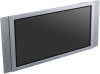
... DVID (HDCP), HD-15 (RBG), HD-15 (YUV/Component), Composite Y/C(S-Video) inputs provide hook-up flexibility. This display includes analog and digital inputs for both video and PC devices for PC and HDTV content. s High Definition (WXGA) Plasma Brilliant image...application. s Flexible Option Boards Optional input boards to display over 1 billion colors delivers hi-contrast video and sharp text for corporate and consumer applications that delivers high image quality, accurate color reproduction and long panel life. FWD-50PX2 Plasma Display FWD-50PX2 is a 50-inch High Definition ...
... DVID (HDCP), HD-15 (RBG), HD-15 (YUV/Component), Composite Y/C(S-Video) inputs provide hook-up flexibility. This display includes analog and digital inputs for both video and PC devices for PC and HDTV content. s High Definition (WXGA) Plasma Brilliant image...application. s Flexible Option Boards Optional input boards to display over 1 billion colors delivers hi-contrast video and sharp text for corporate and consumer applications that delivers high image quality, accurate color reproduction and long panel life. FWD-50PX2 Plasma Display FWD-50PX2 is a 50-inch High Definition ...
Brochure
Page 2
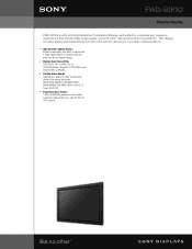
... up to change without notice. Also, allows room for hospitality or home use BKM-FW11: Component/5 BNC input BKM-FW12: Component/RGB loop through. ©2005 Sony Electronics Inc. Non-metric weights and measures are subject to 15 degrees). Operating System Compatibility: N/A Picture Modes... perfect for EBS accessories. Limited Warranty: 2 years parts, 2 years labor, 1 year panel including on -site service in most areas. FWD-50PX2 Plasma Display specifications Screen Size: 50.0" Audio Power Output: 14W Total (7Wx2 Digital AMP) Cable Management System: Yes On Screen Controls: Yes...
... up to change without notice. Also, allows room for hospitality or home use BKM-FW11: Component/5 BNC input BKM-FW12: Component/RGB loop through. ©2005 Sony Electronics Inc. Non-metric weights and measures are subject to 15 degrees). Operating System Compatibility: N/A Picture Modes... perfect for EBS accessories. Limited Warranty: 2 years parts, 2 years labor, 1 year panel including on -site service in most areas. FWD-50PX2 Plasma Display specifications Screen Size: 50.0" Audio Power Output: 14W Total (7Wx2 Digital AMP) Cable Management System: Yes On Screen Controls: Yes...
User Manual
Page 3
...) Using On-screen Menus 16 (GB) Operating Through Menus 16 (GB) Menu Guide 16 (GB) GB Watching the Picture 22 (GB) Switching the Input Signal 22 (GB) Input Signal, Picture Mode and Display Status Information 23 (GB) Selecting Image Quality 25 (GB) Adjusting the Picture 25 (GB) Adjusting the Contrast, Brightness, Chroma...
...) Using On-screen Menus 16 (GB) Operating Through Menus 16 (GB) Menu Guide 16 (GB) GB Watching the Picture 22 (GB) Switching the Input Signal 22 (GB) Input Signal, Picture Mode and Display Status Information 23 (GB) Selecting Image Quality 25 (GB) Adjusting the Picture 25 (GB) Adjusting the Contrast, Brightness, Chroma...
User Manual
Page 8
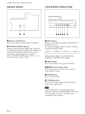
... from the Remote Commander. 2 POWER/STANDBY indicator Lights up in orange when the display enters the power saving mode while a signal is input from the INPUT or OPTION connector. When the POWER/STANDBY indicator blinks, see "Selfdiagnosis Function" on the display unit. Lights up in red in the ...OPTION slot, OPTION will be input switches as follows each time you press the INPUT button. Wait about 10 seconds after one of these operations before executing the next operation. 8 (GB) Press again to...
... from the Remote Commander. 2 POWER/STANDBY indicator Lights up in orange when the display enters the power saving mode while a signal is input from the INPUT or OPTION connector. When the POWER/STANDBY indicator blinks, see "Selfdiagnosis Function" on the display unit. Lights up in red in the ...OPTION slot, OPTION will be input switches as follows each time you press the INPUT button. Wait about 10 seconds after one of these operations before executing the next operation. 8 (GB) Press again to...
User Manual
Page 9
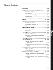
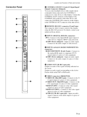
...connect the CONTROL S IN connector on the screen. Connector Panel Location and Function of Parts and Controls 1 CONTROL S IN/OUT (Control S Signal Input/ Output) Connector (Minijack) You can control multiple devices with a single remote commander when connected to the CONTROL S connector of video equipment. AUDIO (...video equipment. VIDEO IN (BNC) : Connects to the digital RGB signal output of video equipment. For details, contact your authorized Sony dealers. 3 INPUT1 (DIGITAL RGB IN) connectors DVI : Connects to the video signal output of a piece of video devices.
...connect the CONTROL S IN connector on the screen. Connector Panel Location and Function of Parts and Controls 1 CONTROL S IN/OUT (Control S Signal Input/ Output) Connector (Minijack) You can control multiple devices with a single remote commander when connected to the CONTROL S connector of video equipment. AUDIO (...video equipment. VIDEO IN (BNC) : Connects to the digital RGB signal output of video equipment. For details, contact your authorized Sony dealers. 3 INPUT1 (DIGITAL RGB IN) connectors DVI : Connects to the video signal output of a piece of video devices.

User Manual
Page 10
... video equipment or a computer. 2 HD VD IN (BNC) : Connects to the audio output of a piece of a computer. 3 AUDIO (Stereo minijack) : Inputs an audio signal. Location and Function of the optional adaptors described below. A blank panel is attached to control the display unit via the network. 8 OPTION2... network management capability, use the OPTION1 slot 7. Optional adaptors (Not supplied) The connectors marked with 7 and 8 on installation, consult your Sony dealers. For details on the connector panel are slot-in type and can be fitted with any of Parts and Controls 7 OPTION1 (VIDEO/COM...
... video equipment or a computer. 2 HD VD IN (BNC) : Connects to the audio output of a piece of a computer. 3 AUDIO (Stereo minijack) : Inputs an audio signal. Location and Function of the optional adaptors described below. A blank panel is attached to control the display unit via the network. 8 OPTION2... network management capability, use the OPTION1 slot 7. Optional adaptors (Not supplied) The connectors marked with 7 and 8 on installation, consult your Sony dealers. For details on the connector panel are slot-in type and can be fitted with any of Parts and Controls 7 OPTION1 (VIDEO/COM...
User Manual
Page 11
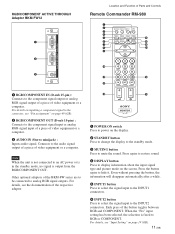
...(GB) Press again to restore sound. 4 DISPLAY button Press to the component signal input or analog RGB signal input of a piece of video equipment or a computer. 3 AUDIO IN (Stereo minijack) : Inputs audio signal. For details, see the documentation of the button toggles between RGB and COMPONENT...456 789 qa 0 qk qs ON SET 1 RGB/COMPONENT IN (D-sub 15-pin) : Connects to the INPUT2 connectors. For details, see "Input Setting" on the screen. Even without pressing the button, the information will disappear automatically after a while. 5 INPUT1 button Press to select the signal...
...(GB) Press again to restore sound. 4 DISPLAY button Press to the component signal input or analog RGB signal input of a piece of video equipment or a computer. 3 AUDIO IN (Stereo minijack) : Inputs audio signal. For details, see the documentation of the button toggles between RGB and COMPONENT...456 789 qa 0 qk qs ON SET 1 RGB/COMPONENT IN (D-sub 15-pin) : Connects to the INPUT2 connectors. For details, see "Input Setting" on the screen. Even without pressing the button, the information will disappear automatically after a while. 5 INPUT1 button Press to select the signal...

User Manual
Page 12
Location and Function of Parts and Controls 7 PICTURE button Selects Picture mode. Each press toggles between Vivid, Standard, and User 1 to 3. 8 ASPECT button Press to change the aspect ratio. 9 M/m/
Location and Function of Parts and Controls 7 PICTURE button Selects Picture mode. Each press toggles between Vivid, Standard, and User 1 to 3. 8 ASPECT button Press to change the aspect ratio. 9 M/m/
User Manual
Page 16
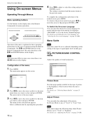
Note Operation may differ in these operating instructions for menu operations. Using On-screen Menus Using On-screen Menus Operating Through Menus Menu operating buttons Use the buttons on the display. Remote Commander MENU Control button section ENTER Operation of operation using the Remote Commander. The M/m and ENTER buttons on the Remote Commander have the same functions as the M/m and ENTER buttons on the display unit or the Remote Commander for the case of the unit is explained in some cases since there is no
Note Operation may differ in these operating instructions for menu operations. Using On-screen Menus Using On-screen Menus Operating Through Menus Menu operating buttons Use the buttons on the display. Remote Commander MENU Control button section ENTER Operation of operation using the Remote Commander. The M/m and ENTER buttons on the Remote Commander have the same functions as the M/m and ENTER buttons on the display unit or the Remote Commander for the case of the unit is explained in some cases since there is no
User Manual
Page 18
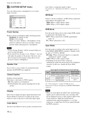
... Matrix to an RGB signal digital tuner, etc. DTV: When connected to show pictures in natural color tones when a component signal is input to the signal input at pin 13 of the picture is connected to the display unit. In that you can be selected. In this case, an image ... is reduced so that case, change the Sync Mode setting. CC1-4: Displays the caption superimposed on page 36 (GB). Notes • There are some inputs for about five seconds on the screen when you select "Reduce," the brightness of the RGB/COMPONENT connector. Using On-screen Menus CUSTOM SETUP menu...
... Matrix to an RGB signal digital tuner, etc. DTV: When connected to show pictures in natural color tones when a component signal is input to the signal input at pin 13 of the picture is connected to the display unit. In that you can be selected. In this case, an image ... is reduced so that case, change the Sync Mode setting. CC1-4: Displays the caption superimposed on page 36 (GB). Notes • There are some inputs for about five seconds on the screen when you select "Reduce," the brightness of the RGB/COMPONENT connector. Using On-screen Menus CUSTOM SETUP menu...
User Manual
Page 19
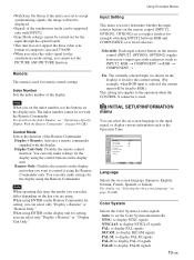
...boards. • This unit does not support the three value sync format of the Remote Commander. Remote This menu is selected, the current input will not be displayed. • Signals of the synchronous mode can select only "Display + Remote" or "Remote Only." Remote Only: Disables... the controls on -screen language or the input signal, or display various information such as INPUT2: RGB t COMPONENT t RGB t COMPONENT...). INITIAL SETUP/INFORMATION menu You can select the on the...
...boards. • This unit does not support the three value sync format of the Remote Commander. Remote This menu is selected, the current input will not be displayed. • Signals of the synchronous mode can select only "Display + Remote" or "Remote Only." Remote Only: Disables... the controls on -screen language or the input signal, or display various information such as INPUT2: RGB t COMPONENT t RGB t COMPONENT...). INITIAL SETUP/INFORMATION menu You can select the on the...
User Manual
Page 20
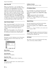
... Operation Time: Software Version: Software Version Indicates the system software version. Manual: Manually configure an IP address. While in memory each input signal on the unit and automatically detects the last setting in the power saving mode, the display unit is automatically turned on page 42... Screen Adjust When "Auto Screen Adjust" is set to On, it saves the screen-settings for size and positioning for each time input signals are switched, the original factory settings operate. All Reset This menu is used for displaying various information, including information on . ...
... Operation Time: Software Version: Software Version Indicates the system software version. Manual: Manually configure an IP address. While in memory each input signal on the unit and automatically detects the last setting in the power saving mode, the display unit is automatically turned on page 42... Screen Adjust When "Auto Screen Adjust" is set to On, it saves the screen-settings for size and positioning for each time input signals are switched, the original factory settings operate. All Reset This menu is used for displaying various information, including information on . ...
User Manual
Page 22
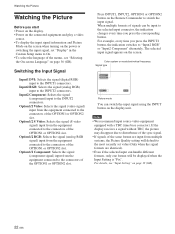
..., the indication switches to the connectors of the OPTION1 or OPTION2 slot. Option1/2 Video: Selects the signal (video signal) input from the equipment connected to the connectors of the OPTION1 or OPTION2 slot. For example, every time you press the corresponding button. ...The selected input signal appears on the screen. Option1/2 Component: Selects the signal (component signal) input from the equipment connected to "Input2 RGB" or "Input2 Component" alternately. Watching the Picture ...
..., the indication switches to the connectors of the OPTION1 or OPTION2 slot. Option1/2 Video: Selects the signal (video signal) input from the equipment connected to the connectors of the OPTION1 or OPTION2 slot. For example, every time you press the corresponding button. ...The selected input signal appears on the screen. Option1/2 Component: Selects the signal (component signal) input from the equipment connected to "Input2 RGB" or "Input2 Component" alternately. Watching the Picture ...
User Manual
Page 23
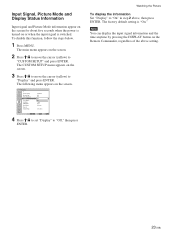
... "Display" to "Display" and press ENTER. To disable this function, follow the steps below. 1 Press MENU. Note You can display the input signal information and the time anytime by pressing the DISPLAY button on the Remote Commander, regardless of the above , then press ENTER. The following ...step 2 above setting. 23 (GB) CUSTOM SETUP Power Saving: Speaker Out: Closed Caption: Display: Color Matrix: HD Mode: RGB Mode: Sync Mode: Remote Input Setting: Standard Off Off Off OY/nPB/PR 1080i DTV H/Comp Selectable Select Set ENTER Exit MENU 4 Press M/m to set "Display" to "CUSTOM SETUP"...
... "Display" to "Display" and press ENTER. To disable this function, follow the steps below. 1 Press MENU. Note You can display the input signal information and the time anytime by pressing the DISPLAY button on the Remote Commander, regardless of the above , then press ENTER. The following ...step 2 above setting. 23 (GB) CUSTOM SETUP Power Saving: Speaker Out: Closed Caption: Display: Color Matrix: HD Mode: RGB Mode: Sync Mode: Remote Input Setting: Standard Off Off Off OY/nPB/PR 1080i DTV H/Comp Selectable Select Set ENTER Exit MENU 4 Press M/m to set "Display" to "CUSTOM SETUP"...

User Manual
Page 24
... is set to digital RGB. Option1/2 Component The signal mode of INPUT1 is set to analog RGB. NTSC (e.g.) The selected input signal is no input signal. INPUT2 RGB The signal mode of OPTION1 or OPTION2 slot is set to component video. Option1/2 S Video The signal... ** cannot automatically be distinguished from the Macintosh computer will not be guaranteed for those signals will be applied consequently. Watching the Picture Preset input signals Signal name Color system or horizontal/ vertical frequency Computer signals 1 VGAa)-1 (VGA 350) 31.5 kHz 70 Hz 2 640×...
... is set to digital RGB. Option1/2 Component The signal mode of INPUT1 is set to analog RGB. NTSC (e.g.) The selected input signal is no input signal. INPUT2 RGB The signal mode of OPTION1 or OPTION2 slot is set to component video. Option1/2 S Video The signal... ** cannot automatically be distinguished from the Macintosh computer will not be guaranteed for those signals will be applied consequently. Watching the Picture Preset input signals Signal name Color system or horizontal/ vertical frequency Computer signals 1 VGAa)-1 (VGA 350) 31.5 kHz 70 Hz 2 640×...
User Manual
Page 25
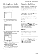
...," "Noise Reduct.," "Dynamic Picture," "Color Temp." Adjust the contrast with moderate contrast and image contour. User1-3: You can set an image quality suitable for each input signal separately. Set the Picture Mode to any of the location where the unit is installed. 1 Press MENU. You can also store the adjusted levels...
...," "Noise Reduct.," "Dynamic Picture," "Color Temp." Adjust the contrast with moderate contrast and image contour. User1-3: You can set an image quality suitable for each input signal separately. Set the Picture Mode to any of the location where the unit is installed. 1 Press MENU. You can also store the adjusted levels...
User Manual
Page 27
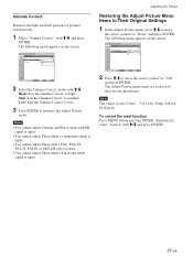
...3 Press ENTER to return to medium. Notes • You cannot adjust Chroma and Phase when an RGB signal is input. • You cannot adjust Phase when a component signal is input. PICTURE/SOUND CONTROL Adjust Picture Gamma Correct.: Reset Mid Cancel OK Select Set ENTER Exit MENU 2 Press M/m to.... Gamma Correct. with a PAL, PAL-M, PAL-N, PAL60, or SECAM color system. • You cannot adjust Phase when a black-and-white signal is input. • You cannot adjust Phase with M/m and press ENTER. to the Adjust Picture menu. mode with M/m and press ENTER. 27 (GB) The following...
...3 Press ENTER to return to medium. Notes • You cannot adjust Chroma and Phase when an RGB signal is input. • You cannot adjust Phase when a component signal is input. PICTURE/SOUND CONTROL Adjust Picture Gamma Correct.: Reset Mid Cancel OK Select Set ENTER Exit MENU 2 Press M/m to.... Gamma Correct. with a PAL, PAL-M, PAL-N, PAL60, or SECAM color system. • You cannot adjust Phase when a black-and-white signal is input. • You cannot adjust Phase with M/m and press ENTER. to the Adjust Picture menu. mode with M/m and press ENTER. 27 (GB) The following...
User Manual
Page 29
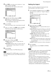
... image is . The following menu appears on the type of picture.) Subtitle: Enlarges the picture all the way to the SCREEN CONTROL menu. Note While inputting DVI or RGB signals, you set the Auto Wide because the Auto Wide function does not work. Wide Zoom: Enlarges 4:3 pictures full-screen to the...
... image is . The following menu appears on the type of picture.) Subtitle: Enlarges the picture all the way to the SCREEN CONTROL menu. Note While inputting DVI or RGB signals, you set the Auto Wide because the Auto Wide function does not work. Wide Zoom: Enlarges 4:3 pictures full-screen to the...
User Manual
Page 30
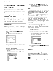
... setting is improper, adjust the screen. 1 Select "Adjust Screen" with M/m/ You can confirm the current setting by the information on the current input signal displayed in the image, there may be times when noise continues to adjust and press ENTER. Adjust screen If there is too much noise... vertical and horizontal size of the screen when you press DISPLAY on the screen. (When you execute "Auto Adjust," the appropriate settings for the current input signal. SCREEN CONTROL Adjust Screen Auto Adjust Dot Phase: Total H Pixel: H Size: H Shift: V Size: V Shift: Reset 28 1344 30 30 30 30...
... setting is improper, adjust the screen. 1 Select "Adjust Screen" with M/m/ You can confirm the current setting by the information on the current input signal displayed in the image, there may be times when noise continues to adjust and press ENTER. Adjust screen If there is too much noise... vertical and horizontal size of the screen when you press DISPLAY on the screen. (When you execute "Auto Adjust," the appropriate settings for the current input signal. SCREEN CONTROL Adjust Screen Auto Adjust Dot Phase: Total H Pixel: H Size: H Shift: V Size: V Shift: Reset 28 1344 30 30 30 30...
User Manual
Page 33
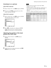
Zooming in on a picture When P&P is selected 1 Select "Picture Size" with M/m and press ENTER. 2 Keep pressing
Zooming in on a picture When P&P is selected 1 Select "Picture Size" with M/m and press ENTER. 2 Keep pressing
