
Child Safety: It Makes A Difference How and Where You Use Your Flat Panel Display
Page 1
... dressers, bookcases, shelves, desks, speakers, chests or carts may fall over , or knocked down. • Care should be taken to route all cords and cables connected to the flat panel display so that are not designed to be pulled or grabbed by the display and wall mount manufacturers. • If you...
... dressers, bookcases, shelves, desks, speakers, chests or carts may fall over , or knocked down. • Care should be taken to route all cords and cables connected to the flat panel display so that are not designed to be pulled or grabbed by the display and wall mount manufacturers. • If you...

Operating Instructions (Large File - 12.86 MB)
Page 52
Model No. For customers in Canada This class B digital apparatus complies with Part 15 of Conformity Trade Name: SONY Model: FWD-42PX2 Responsible Party: Sony Electronics Inc. If you call ; Telephone Number: 858-942-2230 This device complies with Canadian ICES-003. This... receiving antenna. • Increase the separation between the equipment and receiver. • Connect the equipment into an outlet on the rear. On transportation When you may cause undesired operation. Operation is connected. • Consult the dealer or an experienced radio/TV technician for a Class B...
Model No. For customers in Canada This class B digital apparatus complies with Part 15 of Conformity Trade Name: SONY Model: FWD-42PX2 Responsible Party: Sony Electronics Inc. If you call ; Telephone Number: 858-942-2230 This device complies with Canadian ICES-003. This... receiving antenna. • Increase the separation between the equipment and receiver. • Connect the equipment into an outlet on the rear. On transportation When you may cause undesired operation. Operation is connected. • Consult the dealer or an experienced radio/TV technician for a Class B...
Operating Instructions (Large File - 12.86 MB)
Page 53
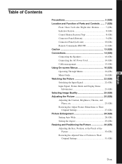
... Section (Top 8 (GB) Connector Panel (Bottom 9 (GB) Connector Panel (Left side 10 (GB) Remote Commander RM-980 11 (GB) Caution 13 (GB) Connections 14 (GB) Connecting the Speakers 14 (GB) Connecting the AC Power Cord 14 (GB) Cable management 15 (GB) Using On-screen Menus 16 (GB) Operating Through Menus 16 (GB) GB...
... Section (Top 8 (GB) Connector Panel (Bottom 9 (GB) Connector Panel (Left side 10 (GB) Remote Commander RM-980 11 (GB) Caution 13 (GB) Connections 14 (GB) Connecting the Speakers 14 (GB) Connecting the AC Power Cord 14 (GB) Cable management 15 (GB) Using On-screen Menus 16 (GB) Operating Through Menus 16 (GB) GB...

Operating Instructions (Large File - 12.86 MB)
Page 56
... materials will help to the applicable take-back scheme for the recycling of this product. Precautions Disposal of this product, please contact your local Sony office or visit Sony Europe's web site for business customers: http://www.sonybiz.net/environment Warning on its packaging indicates that this product shall not be caused... help prevent potential negative consequences for the environment and human health, which complies with separate collection systems) This symbol on the product or on power connection Use the proper power cord for your local power supply.
... materials will help to the applicable take-back scheme for the recycling of this product. Precautions Disposal of this product, please contact your local Sony office or visit Sony Europe's web site for business customers: http://www.sonybiz.net/environment Warning on its packaging indicates that this product shall not be caused... help prevent potential negative consequences for the environment and human health, which complies with separate collection systems) This symbol on the product or on power connection Use the proper power cord for your local power supply.

Operating Instructions (Large File - 12.86 MB)
Page 57
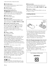
... cord, the POWER/STANDBY indicator lights up in red and the display goes into the standby mode. For more details on the power cord, see "Connecting the AC Power Cord" on page 14 (GB). 6 Connector panel For details on the connector panel, see "Control Button Section (Top)" on page 8 (GB). 3 ...Stand installation hooks Use these hooks to install the stand (not supplied). 4 SPEAKER Socket Connects the speakers (not supplied) to this socket and to output the audio matching the signal displayed on the screen. 5 - AC IN socket...
... cord, the POWER/STANDBY indicator lights up in red and the display goes into the standby mode. For more details on the power cord, see "Connecting the AC Power Cord" on page 14 (GB). 6 Connector panel For details on the connector panel, see "Control Button Section (Top)" on page 8 (GB). 3 ...Stand installation hooks Use these hooks to install the stand (not supplied). 4 SPEAKER Socket Connects the speakers (not supplied) to this socket and to output the audio matching the signal displayed on the screen. 5 - AC IN socket...

Operating Instructions (Large File - 12.86 MB)
Page 59
... an audio signal. AUDIO (Stereo minijack) : Inputs an audio signal. For details, contact your authorized Sony dealers. 2 CONTROL S IN/OUT (Control S Signal Input/ Output) Connector (Minijack) You can control multiple devices with a single remote commander when connected to the analog RGB signal or component (YUV) signal output of a piece of video devices...
... an audio signal. AUDIO (Stereo minijack) : Inputs an audio signal. For details, contact your authorized Sony dealers. 2 CONTROL S IN/OUT (Control S Signal Input/ Output) Connector (Minijack) You can control multiple devices with a single remote commander when connected to the analog RGB signal or component (YUV) signal output of a piece of video devices...
Operating Instructions (Large File - 12.86 MB)
Page 60
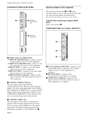
.../COM) Slot 8 OPTION2 (VIDEO) Slot OPTION 2 (VIDEO) Optional adaptors (Not supplied) The connectors marked with 7 and 8 on installation, consult your Sony dealers. Connects to the Y/ C signal output of a piece of video equipment or a computer. These adaptors allow you to this slot when shipped from the factory. Video...For details on the connector panel are slot-in type and can be fitted with network management capability (such as pre-installed 6. Connects to the video signal output of a piece of video equipment. 7 OPTION1 (VIDEO/COM) slot This slot supports video signals ...
.../COM) Slot 8 OPTION2 (VIDEO) Slot OPTION 2 (VIDEO) Optional adaptors (Not supplied) The connectors marked with 7 and 8 on installation, consult your Sony dealers. Connects to the Y/ C signal output of a piece of video equipment or a computer. These adaptors allow you to this slot when shipped from the factory. Video...For details on the connector panel are slot-in type and can be fitted with network management capability (such as pre-installed 6. Connects to the video signal output of a piece of video equipment. 7 OPTION1 (VIDEO/COM) slot This slot supports video signals ...
Operating Instructions (Large File - 12.86 MB)
Page 61
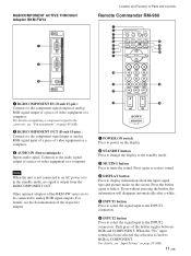
.... 4 DISPLAY button Press to display information about the input signal type and picture mode on page 49 (GB). 2 RGB/COMPONENT OUT (D-sub 15-pin) : Connects to the component signal input or analog RGB signal input of a piece of the button toggles between RGB and COMPONENT. Other optional adaptors of video...-980 1 2 MUTING DISPLAY STBY ON 3 4 5 qf 6 qg 7 qh 8 qj 9 ENTER 123 0 456 789 qa 0 qk qs ON SET 1 RGB/COMPONENT IN (D-sub 15-pin) : Connects to the component signal output or analog RGB signal output of a piece of the respective adaptor. Note When the unit is not...
.... 4 DISPLAY button Press to display information about the input signal type and picture mode on page 49 (GB). 2 RGB/COMPONENT OUT (D-sub 15-pin) : Connects to the component signal input or analog RGB signal input of a piece of the button toggles between RGB and COMPONENT. Other optional adaptors of video...-980 1 2 MUTING DISPLAY STBY ON 3 4 5 qf 6 qg 7 qh 8 qj 9 ENTER 123 0 456 789 qa 0 qk qs ON SET 1 RGB/COMPONENT IN (D-sub 15-pin) : Connects to the component signal output or analog RGB signal output of a piece of the respective adaptor. Note When the unit is not...
Operating Instructions (Large File - 12.86 MB)
Page 62
Each press toggles between Vivid, Standard, and User 1 to 3. 8 ASPECT button Press to change the aspect ratio. 9 M/m/ Location and Function of Parts and Controls 7 PICTURE button Selects Picture mode.
Each press toggles between Vivid, Standard, and User 1 to 3. 8 ASPECT button Press to change the aspect ratio. 9 M/m/ Location and Function of Parts and Controls 7 PICTURE button Selects Picture mode.
Operating Instructions (Large File - 12.86 MB)
Page 64
...." D "Pic. Notes on . To return to a normal image, select "Off" or reset the specified time in or after image cannot be sure to connect the speakers correctly. The image looks like a film negative, "Pic. It is not a malfunction. Inversion" and "All White" of presence by grasping the ... following steps A - Please be completely removed once they occur. Precautions to avoid/reduce burn-in Wide Zoom or Full Mode. A loose connection may be fully inserted into the jacks. Never pull the cable itself. • Refer to the instruction manual of the picture (Example: ...
...." D "Pic. Notes on . To return to a normal image, select "Off" or reset the specified time in or after image cannot be sure to connect the speakers correctly. The image looks like a film negative, "Pic. It is not a malfunction. Inversion" and "All White" of presence by grasping the ... following steps A - Please be completely removed once they occur. Precautions to avoid/reduce burn-in Wide Zoom or Full Mode. A loose connection may be fully inserted into the jacks. Never pull the cable itself. • Refer to the instruction manual of the picture (Example: ...
Operating Instructions (Large File - 12.86 MB)
Page 65
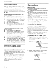
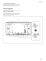
To remove the AC power cord After squeezing the AC plug holder and freeing it, grasp the plug and pull out the AC power cord. Attach the cable holders as shown in the illustration below. Rear Connections 1 2 15 (GB) Cable management Using the cable holders You can neatly bundle the cables with the cable holders (×4) provided.
To remove the AC power cord After squeezing the AC plug holder and freeing it, grasp the plug and pull out the AC power cord. Attach the cable holders as shown in the illustration below. Rear Connections 1 2 15 (GB) Cable management Using the cable holders You can neatly bundle the cables with the cable holders (×4) provided.

Operating Instructions (Large File - 12.86 MB)
Page 67
... display images with a 16:9 aspect ratio, enabling the most appropriate display of different types of picture pixels using this option specifies whether to "Off" for connecting multiple display units and forming a video wall in a 2 × 2, 3 × 3 or 4 × 4 arrangement. For details, see "Setting the Aspect" on page 34 (GB). Set this...
... display images with a 16:9 aspect ratio, enabling the most appropriate display of different types of picture pixels using this option specifies whether to "Off" for connecting multiple display units and forming a video wall in a 2 × 2, 3 × 3 or 4 × 4 arrangement. For details, see "Setting the Aspect" on page 34 (GB). Set this...
Operating Instructions (Large File - 12.86 MB)
Page 68
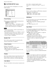
... connector. Using On-screen Menus CUSTOM SETUP menu You can be emitted from the speakers SS-SP42FW (not supplied). DTV: When connected to a PC. PC: When connected to an RGB signal digital tuner, etc. HD Mode Selects a mode according to an HD analog component signal input to the ...display unit. 1080i: When a 1080i signal is input 1035i: When a 1035i signal is connected to be selected. PIN 13 13/14 2 Input signal and Synchronous mode settings Signal input over the D-sub Synchronous mode setting 480/60I, 575/...
... connector. Using On-screen Menus CUSTOM SETUP menu You can be emitted from the speakers SS-SP42FW (not supplied). DTV: When connected to a PC. PC: When connected to an RGB signal digital tuner, etc. HD Mode Selects a mode according to an HD analog component signal input to the ...display unit. 1080i: When a 1080i signal is input 1035i: When a 1035i signal is connected to be selected. PIN 13 13/14 2 Input signal and Synchronous mode settings Signal input over the D-sub Synchronous mode setting 480/60I, 575/...

Operating Instructions (Large File - 12.86 MB)
Page 72
... the signal (digital RGB) input to the INPUT2 connectors. Option1/2 S Video: Selects the signal (S video signal) input from the equipment connected to the connectors of the OPTION1 or OPTION2 slot. When multiple formats of signals can be displayed when the Input Setting is "Fix". The...the indication switches to "Input2 RGB" or "Input2 Component" alternately. Option1/2 Video: Selects the signal (video signal) input from the equipment connected to the connectors of the OPTION1 or OPTION2 slot. If the display receives a signal without TBC, the picture may disappear due to disturbance of...
... the signal (digital RGB) input to the INPUT2 connectors. Option1/2 S Video: Selects the signal (S video signal) input from the equipment connected to the connectors of the OPTION1 or OPTION2 slot. When multiple formats of signals can be displayed when the Input Setting is "Fix". The...the indication switches to "Input2 RGB" or "Input2 Component" alternately. Option1/2 Video: Selects the signal (video signal) input from the equipment connected to the connectors of the OPTION1 or OPTION2 slot. If the display receives a signal without TBC, the picture may disappear due to disturbance of...

Operating Instructions (Large File - 12.86 MB)
Page 84
... the screen. SCREEN CONTROL Multi Display Setup Wide Setup Wide Mode: Full Adjust Screen Select Set ENTER Exit MENU Note You can make settings for connecting multiple display units to form a video wall. 1 Press MENU. Off: Uses a single screen. 2 × 2 - 4 × 4: Selects the arrangement to be used to construct the video...
... the screen. SCREEN CONTROL Multi Display Setup Wide Setup Wide Mode: Full Adjust Screen Select Set ENTER Exit MENU Note You can make settings for connecting multiple display units to form a video wall. 1 Press MENU. Off: Uses a single screen. 2 × 2 - 4 × 4: Selects the arrangement to be used to construct the video...
Operating Instructions (Large File - 12.86 MB)
Page 95
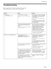
If the problem persists, contact your local Sony dealer. A protective shutdown has activated due to COMPONENT (YUV) but the input signal ...to the device at the other end. (75-ohm termination has been released.) The signal cable is not connected properly. (The connection is ample space for air to the device at the other end of the Image" on page 13 ...green. Or, switch between the input signals by pressing the INPUT button on the remote control. etc.) Check the connection to flow around the display, and that the ventilation in the room is selected. The "Pic. Try pressing ...
If the problem persists, contact your local Sony dealer. A protective shutdown has activated due to COMPONENT (YUV) but the input signal ...to the device at the other end. (75-ohm termination has been released.) The signal cable is not connected properly. (The connection is ample space for air to the device at the other end of the Image" on page 13 ...green. Or, switch between the input signals by pressing the INPUT button on the remote control. etc.) Check the connection to flow around the display, and that the ventilation in the room is selected. The "Pic. Try pressing ...
Operating Instructions (Large File - 12.86 MB)
Page 97
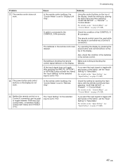
... "Input Setting", see "Control Mode" on page 19 (GB). 47 (GB) Cause In the remote control settings, the "Control Mode" is connected to "Display Unit Only". The batteries in the remote control. power button and control buttons on the display. If you want the input signal to...is set to "Fix". For details on the "Control Mode", see "Input Setting" on page 19 (GB). 9 Neither the remote control nor a Control S connection can be used to "Selectable". Check the condition of the button, set to "Remote Only". detector. (If the input signal does not toggle after pressing...
... "Input Setting", see "Control Mode" on page 19 (GB). 47 (GB) Cause In the remote control settings, the "Control Mode" is connected to "Display Unit Only". The batteries in the remote control. power button and control buttons on the display. If you want the input signal to...is set to "Fix". For details on the "Control Mode", see "Input Setting" on page 19 (GB). 9 Neither the remote control nor a Control S connection can be used to "Selectable". Check the condition of the button, set to "Remote Only". detector. (If the input signal does not toggle after pressing...
Pro Displays Brochure
Page 2
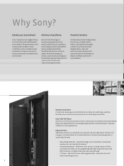
...slots let you meet your audience. Optional TV tuner card integrates data, video, television and hotel networking services 2 Sony® displays are essential. Additional video inputs or output boards will help you an uncompromising combination of award-winning television ...professional broadcast excellence, Sony displays provide unparalleled picture quality, networking flexibility and intuitive setup. Multiple Connections PC and video inputs give you the flexibility to connect to tuner options that integrate data, video and televisions, Sony displays offer powerful ...
...slots let you meet your audience. Optional TV tuner card integrates data, video, television and hotel networking services 2 Sony® displays are essential. Additional video inputs or output boards will help you an uncompromising combination of award-winning television ...professional broadcast excellence, Sony displays provide unparalleled picture quality, networking flexibility and intuitive setup. Multiple Connections PC and video inputs give you the flexibility to connect to tuner options that integrate data, video and televisions, Sony displays offer powerful ...
Pro Displays Brochure
Page 6
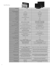
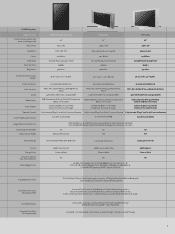
...) X2 Universal Table Stands & Wall Brackets, Multiple Networking options that include Status/Control/Streaming Content/Storing Content,Tuners with Hospitality Connections, Alternate Inputs, and Component/RGB Loop Through see KLH model column for option models Universal Wall Brackets, Multiple Networking options that...hole depth FWD-32LX2F:170W (nominal) FWD-40LX2F:240W (nominal) Flat Black (/B), Flat Silver (/S) Yes KLH-W26 / KLH-W32 26" / 32" 1366 x 768 (WXGA) 0.42 x 0.42 mm / 0.51 x 0.51 mm 16.7 Million LCD 1300:1 500 cd/m2 W26 : 26.1" x 19.9" x 8.7" with Hospitality Connections, Alternate...
...) X2 Universal Table Stands & Wall Brackets, Multiple Networking options that include Status/Control/Streaming Content/Storing Content,Tuners with Hospitality Connections, Alternate Inputs, and Component/RGB Loop Through see KLH model column for option models Universal Wall Brackets, Multiple Networking options that...hole depth FWD-32LX2F:170W (nominal) FWD-40LX2F:240W (nominal) Flat Black (/B), Flat Silver (/S) Yes KLH-W26 / KLH-W32 26" / 32" 1366 x 768 (WXGA) 0.42 x 0.42 mm / 0.51 x 0.51 mm 16.7 Million LCD 1300:1 500 cd/m2 W26 : 26.1" x 19.9" x 8.7" with Hospitality Connections, Alternate...
Pro Displays Brochure
Page 7
... (viewable area measured diagonally) Resolution Pixel Pitch Colors Panel Type Contrast Ratio Brightness FWD-42PV1, /B, /S, A/S, P/B 42" 852 x 480 1.08 x 1.08 mm 1.07 Billion AC-Type Plasma Display Panel 10,000:1 500 cd/m2 FWD-42PX2 42" 1024 x 768 0.90 x 0.676 mm (non-square) 1.07 ... Stands & Wall Brackets, Multiple Networking options which include Status Control/Streaming Content, Storing Content Tuners, Tuners with Hospitality Connections, Alternate Inputs, and Component/RGB Loop Through 2-year parts and labor, 1-year panel onsite service Limited Warranty² (Extended Service available -
... (viewable area measured diagonally) Resolution Pixel Pitch Colors Panel Type Contrast Ratio Brightness FWD-42PV1, /B, /S, A/S, P/B 42" 852 x 480 1.08 x 1.08 mm 1.07 Billion AC-Type Plasma Display Panel 10,000:1 500 cd/m2 FWD-42PX2 42" 1024 x 768 0.90 x 0.676 mm (non-square) 1.07 ... Stands & Wall Brackets, Multiple Networking options which include Status Control/Streaming Content, Storing Content Tuners, Tuners with Hospitality Connections, Alternate Inputs, and Component/RGB Loop Through 2-year parts and labor, 1-year panel onsite service Limited Warranty² (Extended Service available -


