Operating Instructions
Page 2
... This device may not cause harmful interference, and (2) this device must accept any changes or modifications not expressly approved in this manual could void your Sony dealer regarding this product. Address: 16450 W. Bernardo Dr, San Diego, CA 92127 U.S.A. Operation is subject to the following measures... can cause injury. This equipment has been tested and found to comply with Part 15 of Conformity Trade Name: SONY Model: FWD-40LX1/32LX1R Responsible Party: Sony Electronics Inc. However, there is no guarantee that may cause undesired operation. Serial No. To reduce the risk ...
... This device may not cause harmful interference, and (2) this device must accept any changes or modifications not expressly approved in this manual could void your Sony dealer regarding this product. Address: 16450 W. Bernardo Dr, San Diego, CA 92127 U.S.A. Operation is subject to the following measures... can cause injury. This equipment has been tested and found to comply with Part 15 of Conformity Trade Name: SONY Model: FWD-40LX1/32LX1R Responsible Party: Sony Electronics Inc. However, there is no guarantee that may cause undesired operation. Serial No. To reduce the risk ...
Operating Instructions
Page 4
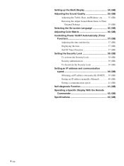
... Security Lock 39 (GB) Setting an IP address and communication speed 39 (GB) Obtaining an IP address automatically (DHCP) .... 39 (GB) Setting an IP address manually (Manual 40 (GB) Setting a communication speed 41 (GB) Self-diagnosis Function 41 (GB) Operating a Specific Display With the Remote Commander 42 (GB) Specifications 43 (GB) 4 (GB...
... Security Lock 39 (GB) Setting an IP address and communication speed 39 (GB) Obtaining an IP address automatically (DHCP) .... 39 (GB) Setting an IP address manually (Manual 40 (GB) Setting a communication speed 41 (GB) Self-diagnosis Function 41 (GB) Operating a Specific Display With the Remote Commander 42 (GB) Specifications 43 (GB) 4 (GB...
Operating Instructions
Page 10
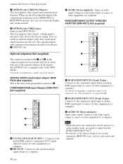
...output of a piece of video equipment or a computer. 2 HD VD IN : Connects to each instruction manual. A blank panel is output from the RGB/COMPONENT OUT. • For details on the Option Adaptors for... 1 2 3 1 RGB/COMPONENT IN (D-sub 15-pin) : Connects to this slot for the FWD-40LX1) This slot supports video signals. The OPTION2 slot is the same as BKM-FW32 or BKM-... VIDEO input/output adaptor BKMFW10 (Not supplied) This is equipped only on installation, consult your Sony dealers. The optional adaptor with communication function such as the preinstalled connectors 6. When you can...
...output of a piece of video equipment or a computer. 2 HD VD IN : Connects to each instruction manual. A blank panel is output from the RGB/COMPONENT OUT. • For details on the Option Adaptors for... 1 2 3 1 RGB/COMPONENT IN (D-sub 15-pin) : Connects to this slot for the FWD-40LX1) This slot supports video signals. The OPTION2 slot is the same as BKM-FW32 or BKM-... VIDEO input/output adaptor BKMFW10 (Not supplied) This is equipped only on installation, consult your Sony dealers. The optional adaptor with communication function such as the preinstalled connectors 6. When you can...
Operating Instructions
Page 14
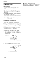
.../32FW (not supplied). For details on how to route the speaker cords, refer to "Using the cable holders" on connecting the speakers, see the operating manual that will securely hold the AC plug. Connecting the Speakers You can enjoy viewing with a greater sense of the two AC plug holders (supplied) that... came with the speakers. AC IN socket cover 14 (GB) Never pull the cable itself. • Refer to the instruction manual of the equipment to the AC power cord.
.../32FW (not supplied). For details on how to route the speaker cords, refer to "Using the cable holders" on connecting the speakers, see the operating manual that will securely hold the AC plug. Connecting the Speakers You can enjoy viewing with a greater sense of the two AC plug holders (supplied) that... came with the speakers. AC IN socket cover 14 (GB) Never pull the cable itself. • Refer to the instruction manual of the equipment to the AC power cord.

Operating Instructions
Page 20
... standby mode is not counted as part of the display unit. Note Time spent in the factory setting. Software Version Indicates the system software version. Manual: Manual configuration to On. Clock Display Displays the currently set to On, requires a password to communicate between the display unit and an optional adaptor with communication...
... standby mode is not counted as part of the display unit. Note Time spent in the factory setting. Software Version Indicates the system software version. Manual: Manual configuration to On. Clock Display Displays the currently set to On, requires a password to communicate between the display unit and an optional adaptor with communication...

Operating Instructions
Page 30
... 50 50 50 Select Set ENTER Exit MENU (2) Select "OK" with M/m and press ENTER. In such cases, adjust the dot phase manually. Adjusting the Size, Position, or the Pixels of the Picture Press MENU to fit the screen, or adjust the vertical and horizontal size ... Size," or "V Shift" on the screen. Resizing and Positioning the Picture Resizing and Positioning the Picture You can adjust the screen either automatically or manually. Adjusting manually (1) Select the item you want to occur even after you select "Dot Phase") Dot Phase: 15 (2) Adjust the screen with M/m and press ...
... 50 50 50 Select Set ENTER Exit MENU (2) Select "OK" with M/m and press ENTER. In such cases, adjust the dot phase manually. Adjusting the Size, Position, or the Pixels of the Picture Press MENU to fit the screen, or adjust the vertical and horizontal size ... Size," or "V Shift" on the screen. Resizing and Positioning the Picture Resizing and Positioning the Picture You can adjust the screen either automatically or manually. Adjusting manually (1) Select the item you want to occur even after you select "Dot Phase") Dot Phase: 15 (2) Adjust the screen with M/m and press ...
Operating Instructions
Page 40
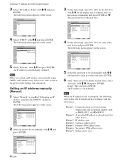
...) Set ENTER Exit MENU 3 Set the three digit value (0 to 255) for all the desired items, select "Execute" with M/m and press ENTER. INITIAL SETUP/INFORMATION Manual IP Address: Subnet Mask: Gateway: Primay DNS: Secondary DNS: Execute 123 . 123 . 012 . 034 000 . 000 . 000 . 000 000 . 000 . 000... Set ENTER Exit MENU 2 Select an item to be displayed in step 4 of "Obtaining an IP address automatically (DHCP)" and press ENTER. INITIAL SETUP/INFORMATION Manual IP Address: Subnet Mask: Gateway: Primay DNS: Secondary DNS: Execute 000 . 000 . 000 . 000 000 . 000 . 000 . 000 000 . 000 . 000...
...) Set ENTER Exit MENU 3 Set the three digit value (0 to 255) for all the desired items, select "Execute" with M/m and press ENTER. INITIAL SETUP/INFORMATION Manual IP Address: Subnet Mask: Gateway: Primay DNS: Secondary DNS: Execute 123 . 123 . 012 . 034 000 . 000 . 000 . 000 000 . 000 . 000... Set ENTER Exit MENU 2 Select an item to be displayed in step 4 of "Obtaining an IP address automatically (DHCP)" and press ENTER. INITIAL SETUP/INFORMATION Manual IP Address: Subnet Mask: Gateway: Primay DNS: Secondary DNS: Execute 000 . 000 . 000 . 000 000 . 000 . 000 . 000 000 . 000 . 000...

