Antenna Installation Hints & Guidelines
Page 1
... Hints Version 0.85 July 18, 2005 Dan Quittman, Sony CS&A WallStation Antenna Antenna Installation Hints and Guidelines Sony Electronics, CS&A dept. 1 Sony Drive Park Ridge, NJ 07656 Disclaimer: Sony Electronics reserves the right to be factually correct, and the reader assumes any time and without notice. Sony does not warrant the information contained to change any...
... Hints Version 0.85 July 18, 2005 Dan Quittman, Sony CS&A WallStation Antenna Antenna Installation Hints and Guidelines Sony Electronics, CS&A dept. 1 Sony Drive Park Ridge, NJ 07656 Disclaimer: Sony Electronics reserves the right to be factually correct, and the reader assumes any time and without notice. Sony does not warrant the information contained to change any...

Antenna Installation Hints & Guidelines
Page 2
WallStation Antenna Hints Version 0.85 July 18, 2005 Dan Quittman, Sony CS&A Antenna Installation Hints and Guidelines General • Keep all local codes. • Any ... AM antenna should be sure to all antenna wiring away from an external antenna throughout the home, be installed by persons knowledgeable and experienced in some types of home construction, particularly those using foil-wrapped insulation and/...that closely parallel AC wires. • All antennas placed behind the wall must be rigidly affixed to studs and conform to use a quality splitter and CATV-type RG-6 coax.
WallStation Antenna Hints Version 0.85 July 18, 2005 Dan Quittman, Sony CS&A Antenna Installation Hints and Guidelines General • Keep all local codes. • Any ... AM antenna should be sure to all antenna wiring away from an external antenna throughout the home, be installed by persons knowledgeable and experienced in some types of home construction, particularly those using foil-wrapped insulation and/...that closely parallel AC wires. • All antennas placed behind the wall must be rigidly affixed to studs and conform to use a quality splitter and CATV-type RG-6 coax.
Antenna Installation Hints & Guidelines
Page 3
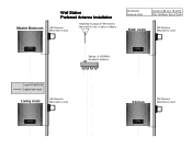
Master Bedroom Wall Station Preferred Antenna Installation AM Antenna Mounted on stud Amplified or passive FM Antenna Mounted on roof, in attic or indoors WallStation Antenna Hints Version 0.85 July 18, 2005 Dan Quittman, Sony CS&A Kids' room AM Antenna Mounted on stud Splitter, 5-1000MHz located at antenna Coax RG-6/RG-59 Captive twin-lead Living room AM Antenna Mounted on stud Kitchen AM Antenna Mounted on stud
Master Bedroom Wall Station Preferred Antenna Installation AM Antenna Mounted on stud Amplified or passive FM Antenna Mounted on roof, in attic or indoors WallStation Antenna Hints Version 0.85 July 18, 2005 Dan Quittman, Sony CS&A Kids' room AM Antenna Mounted on stud Splitter, 5-1000MHz located at antenna Coax RG-6/RG-59 Captive twin-lead Living room AM Antenna Mounted on stud Kitchen AM Antenna Mounted on stud
Antenna Installation Hints & Guidelines
Page 4
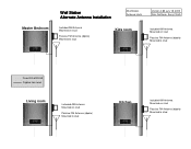
Master Bedroom Wall Station Alternate Antenna Installation WallStation Antenna Hints Version 0.85 July 18, 2005 Dan Quittman, Sony CS&A Included AM Antenna Mounted on stud Passive FM Antenna (dipole) Mounted to stud Kids room Included AM Antenna Mounted on stud Passive FM Antenna (dipole) Mounted to stud Coax RG-6/RG-59 Captive twin-lead Living room Included AM Antenna Mounted on stud Passive FM Antenna (dipole) Mounted to stud Kitchen Included AM Antenna Mounted on stud Passive FM Antenna (dipole) Mounted to stud
Master Bedroom Wall Station Alternate Antenna Installation WallStation Antenna Hints Version 0.85 July 18, 2005 Dan Quittman, Sony CS&A Included AM Antenna Mounted on stud Passive FM Antenna (dipole) Mounted to stud Kids room Included AM Antenna Mounted on stud Passive FM Antenna (dipole) Mounted to stud Coax RG-6/RG-59 Captive twin-lead Living room Included AM Antenna Mounted on stud Passive FM Antenna (dipole) Mounted to stud Kitchen Included AM Antenna Mounted on stud Passive FM Antenna (dipole) Mounted to stud
Installer Manual
Page 1
... place the Unit in a location near the location where the Unit is installed. • There is for the system network. © 2005 Sony Corporation Printed in the Unit. • Do not place the Unit on the wall. On power sources • The Unit is not disconnected from the AC... the player. Make sure to follow the procedure in the wall corresponds to the specified size. You cannot mount it . Connecting a TV (DVP-NW50 only) Connections between the Unit and each of devices are no obstructions, such as a DVD Changer, you may be damaged or fall , causing injury to you install the ...
... place the Unit in a location near the location where the Unit is installed. • There is for the system network. © 2005 Sony Corporation Printed in the Unit. • Do not place the Unit on the wall. On power sources • The Unit is not disconnected from the AC... the player. Make sure to follow the procedure in the wall corresponds to the specified size. You cannot mount it . Connecting a TV (DVP-NW50 only) Connections between the Unit and each of devices are no obstructions, such as a DVD Changer, you may be damaged or fall , causing injury to you install the ...
User Manual
Page 2
...as power-supply cord or plug is subject to provide reasonable protection against harmful interference in the literature accompanying the appliance. Install in this equipment does cause harmful interference to rain or moisture, does not operate normally, or has been dropped. ...the apparatus. 11Only use caution when moving the cart/apparatus combination to Part 15 of Conformity Trade name: SONY Model No.: CDP-NW10/DVP-NW50 Responsible Party: Sony Electronics Inc. If this manual could void your outlet, consult an electrician for help. This equipment generates, ...
...as power-supply cord or plug is subject to provide reasonable protection against harmful interference in the literature accompanying the appliance. Install in this equipment does cause harmful interference to rain or moisture, does not operate normally, or has been dropped. ...the apparatus. 11Only use caution when moving the cart/apparatus combination to Part 15 of Conformity Trade name: SONY Model No.: CDP-NW10/DVP-NW50 Responsible Party: Sony Electronics Inc. If this manual could void your outlet, consult an electrician for help. This equipment generates, ...
User Manual
Page 6
... Two speakers (2CH) (CDP-NW10)/Five speakers and a sub woofer (5.1CH) (DVP-NW50) The main features of the Unit are the following: • Two types of conventional CD player model and a DVD player model with a simple timer clock and 2ch audio input • The Unit can play... to other Units via a network • 2ch to 5.1ch sound produced from connected speakers for DVP-NW50, or 2ch sound produced from Digital Theater System, Inc. Gracenote is installed into the wall of Gracenote. A Unit is the industry standard in music recognition technology and related content delivery. A...
... Two speakers (2CH) (CDP-NW10)/Five speakers and a sub woofer (5.1CH) (DVP-NW50) The main features of the Unit are the following: • Two types of conventional CD player model and a DVD player model with a simple timer clock and 2ch audio input • The Unit can play... to other Units via a network • 2ch to 5.1ch sound produced from connected speakers for DVP-NW50, or 2ch sound produced from Digital Theater System, Inc. Gracenote is installed into the wall of Gracenote. A Unit is the industry standard in music recognition technology and related content delivery. A...
User Manual
Page 7
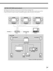
... Speaker Example of multiple Units. It may differ from an actual system network. The configuration shown below illustrates an entire system network made up of a DVP-NW50 system network 7US Contact your nearest installer for details on making the required connections for illustrative purposes only.
... Speaker Example of multiple Units. It may differ from an actual system network. The configuration shown below illustrates an entire system network made up of a DVP-NW50 system network 7US Contact your nearest installer for details on making the required connections for illustrative purposes only.
User Manual
Page 10
...image on the connections required by an installer. If you pass the Unit signals via cables or cords coming through the wall. Contact your TV. Connect the OUTPUT jacks (L/R) of the audio equipment to connect and setup the Unit. Connecting a TV (DVP-NW50 only) Connections between the Unit and ...each of devices are made via the audio connectors on your nearest installer for details on ...
...image on the connections required by an installer. If you pass the Unit signals via cables or cords coming through the wall. Contact your TV. Connect the OUTPUT jacks (L/R) of the audio equipment to connect and setup the Unit. Connecting a TV (DVP-NW50 only) Connections between the Unit and ...each of devices are made via the audio connectors on your nearest installer for details on ...
User Manual
Page 11
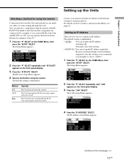
Chapter 1 Getting Started Selecting a method for using the remote Connections between the Unit and each parameters. The Unit directly and through the wall. Because some knowledge of the Unit and the component are connected. The LAN setup Menu appears. 4 Press the "IP ADDRESS" SELECT. The Setup Menu appears. 2 .... • MANUAL: You can acquire the IP address automatically. The default setting is underlined. • AUTO: You can set up the Units Contact your nearest installer for using signals from the remote.
Chapter 1 Getting Started Selecting a method for using the remote Connections between the Unit and each parameters. The Unit directly and through the wall. Because some knowledge of the Unit and the component are connected. The LAN setup Menu appears. 4 Press the "IP ADDRESS" SELECT. The Setup Menu appears. 2 .... • MANUAL: You can acquire the IP address automatically. The default setting is underlined. • AUTO: You can set up the Units Contact your nearest installer for using signals from the remote.
User Manual
Page 48
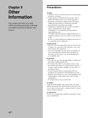
...malfunction. 48US On placement • Place the Unit in a horizontal position only. • Keep the Unit and the discs away from the wall outlet. The use a commercially available cleaning disc. never pull the cord. On cleaning discs Do not use of optional instruments with this product ..., panel, and controls with a soft cloth slightly moistened with adequate ventilation to direct sunlight, excessive dust, or mechanical shock. • Do not install the Unit in the Unit. • Do not place the Unit on a soft surface such as vases, on the Unit. Precautions On safety ...
...malfunction. 48US On placement • Place the Unit in a horizontal position only. • Keep the Unit and the discs away from the wall outlet. The use a commercially available cleaning disc. never pull the cord. On cleaning discs Do not use of optional instruments with this product ..., panel, and controls with a soft cloth slightly moistened with adequate ventilation to direct sunlight, excessive dust, or mechanical shock. • Do not install the Unit in the Unit. • Do not place the Unit on a soft surface such as vases, on the Unit. Precautions On safety ...
User Manual
Page 49
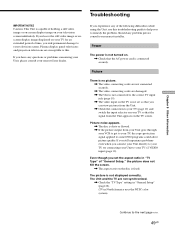
... time, you set so that you experience any problem persist, consult your nearest Sony dealer. If you still experience problems even when you have any questions or problems concerning your Unit, please consult your nearest installer. Continue to remedy the problem. If you leave the still video image or ...televisions are damaged. , The Unit is connected securely. If you can view pictures from your Unit goes through your VCR to get to some DVD programs could affect picture quality. Power The power is not turned on. , Check that the signal from the Unit appears on your TV so...
... time, you set so that you experience any problem persist, consult your nearest Sony dealer. If you still experience problems even when you have any questions or problems concerning your Unit, please consult your nearest installer. Continue to remedy the problem. If you leave the still video image or ...televisions are damaged. , The Unit is connected securely. If you can view pictures from your Unit goes through your VCR to get to some DVD programs could affect picture quality. Power The power is not turned on. , Check that the signal from the Unit appears on your TV so...
User Manual
Page 50
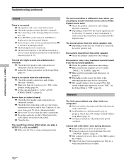
... other room during Intercom. , Intercom Privacy is turned off . , Connection has not been established. There is set "DRC" on the DVD, the output signal may come from the center speaker. , Check the speaker connections and settings. The surround effect is recorded in the speaker...Clean the disc. Chapter 9 Other Information Troubleshooting (continued) Sound There is no sound from the sub woofer. , Check the speaker connections and settings (Installer's manual). , Make sure that the connecting cords are away from a transformer or motor, and at least 3 meters (10 feet) away from your...
... other room during Intercom. , Intercom Privacy is turned off . , Connection has not been established. There is set "DRC" on the DVD, the output signal may come from the center speaker. , Check the speaker connections and settings. The surround effect is recorded in the speaker...Clean the disc. Chapter 9 Other Information Troubleshooting (continued) Sound There is no sound from the sub woofer. , Check the speaker connections and settings (Installer's manual). , Make sure that the connecting cords are away from a transformer or motor, and at least 3 meters (10 feet) away from your...
User Manual
Page 54
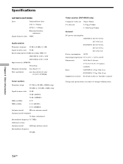
...DVP-NW50 Laser Semiconductor laser (CD: λ = 780nm) (DVD: λ = 650nm) Emission duration: continuous Signal format system NTSC Audio section Frequency response 20 Hz to 20 kHz (± 1 dB) Signal-to-noise ratio 95 dB Rated output power 1kHz into 8ohms THD: 3% CDP-NW10: 30 W + 30 W DVP-NW50...; 266 ✕ 104 mm (9 1/8 ✕ 10 1/2 ✕ 4 1/8 inches) (w/h/d) Mass: CDP-NW10: 2.5 kg (5 lbs 8 oz) DVP-NW50: 2.7 kg (5 lbs 15 oz) Supplied accessories : For details on this see "Installer's manual" Design and specifications are subject to change without notice. 54US
...DVP-NW50 Laser Semiconductor laser (CD: λ = 780nm) (DVD: λ = 650nm) Emission duration: continuous Signal format system NTSC Audio section Frequency response 20 Hz to 20 kHz (± 1 dB) Signal-to-noise ratio 95 dB Rated output power 1kHz into 8ohms THD: 3% CDP-NW10: 30 W + 30 W DVP-NW50...; 266 ✕ 104 mm (9 1/8 ✕ 10 1/2 ✕ 4 1/8 inches) (w/h/d) Mass: CDP-NW10: 2.5 kg (5 lbs 8 oz) DVP-NW50: 2.7 kg (5 lbs 15 oz) Supplied accessories : For details on this see "Installer's manual" Design and specifications are subject to change without notice. 54US
Utility for In-Wall Unit Software User Manual
Page 3
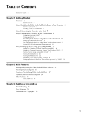
...Getting Started Overview 4 System network 5 Setup 1: Installing the Utility for In-Wall Unit Software to Your Computer 6 System requirements 6 Installing Utility for In-Wall Unit 7 Setup 2: Connecting the Computer to the Unit 7 Setup 3: Setting up the Utility for In-Wall Unit Software 8 Setting up Gracenote CDDBR 8 Setting... up all Units 9 The "Utility for In-Wall Unit Setup Menu" window...
...Getting Started Overview 4 System network 5 Setup 1: Installing the Utility for In-Wall Unit Software to Your Computer 6 System requirements 6 Installing Utility for In-Wall Unit 7 Setup 2: Connecting the Computer to the Unit 7 Setup 3: Setting up the Utility for In-Wall Unit Software 8 Setting up Gracenote CDDBR 8 Setting... up all Units 9 The "Utility for In-Wall Unit Setup Menu" window...

Utility for In-Wall Unit Software User Manual
Page 4
... up the "Server Setup, powered by DiXiM." The features of the Utility for In-Wall Unit software, how to set up the Utility for In-Wall Unit software (such as described. Continue to operate each installed Unit individually or all installed Units simultaneously (page 29) • Getting CD information from the pictures in this...
... up the "Server Setup, powered by DiXiM." The features of the Utility for In-Wall Unit software, how to set up the Utility for In-Wall Unit software (such as described. Continue to operate each installed Unit individually or all installed Units simultaneously (page 29) • Getting CD information from the pictures in this...
Utility for In-Wall Unit Software User Manual
Page 5
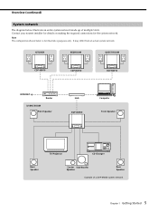
... Rear Speaker Center Sub Woofer Speaker Rear Speaker Example of multiple Units. Note The configuration shown below illustrates an entire system network made up of a DVP-NW50 system network Chapter 1 Getting Started 5 Contact your nearest installer for details on making the required connections for illustrative purposes only.
... Rear Speaker Center Sub Woofer Speaker Rear Speaker Example of multiple Units. Note The configuration shown below illustrates an entire system network made up of a DVP-NW50 system network Chapter 1 Getting Started 5 Contact your nearest installer for details on making the required connections for illustrative purposes only.
Utility for In-Wall Unit Software User Manual
Page 6
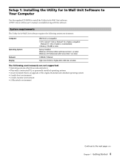
..., 800 x 600 dots or better The following system environment. A PDF version of the original manufacturer-installed operating system • A multi-boot environment • A multi-monitor environment • A Macintosh environment Continue to install the Utility for In-Wall Unit software requires the following environments are not supported: • Operating systems other those indicated above...
..., 800 x 600 dots or better The following system environment. A PDF version of the original manufacturer-installed operating system • A multi-boot environment • A multi-monitor environment • A Macintosh environment Continue to install the Utility for In-Wall Unit software requires the following environments are not supported: • Operating systems other those indicated above...
Utility for In-Wall Unit Software User Manual
Page 7
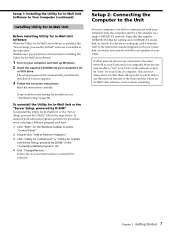
... "Add or Remove Programs." 3 Click "Utility for In-Wall Unit" or "Utility for In-Wall Unit-Server Setup, powered by DiXiM," follow the steps below. If other products will be "seen" by DiXiM" software is installed, the "Server Setup, powered by your computer's CD or DVD drive. Chapter 1 Getting Started 7 The setup program starts...
... "Add or Remove Programs." 3 Click "Utility for In-Wall Unit" or "Utility for In-Wall Unit-Server Setup, powered by DiXiM," follow the steps below. If other products will be "seen" by DiXiM" software is installed, the "Server Setup, powered by your computer's CD or DVD drive. Chapter 1 Getting Started 7 The setup program starts...
Utility for In-Wall Unit Software User Manual
Page 14
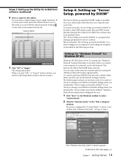
...the station name from the list. Settings for "Windows Firewall" for the station. If you choose to change your Windows Firewall settings when you installed the "Server Setup, powered by DiXiM" makes it possible for you. 1 Click "Start" on the Windows taskbar to select "Control Panel." ... not choose to change your Windows Firewall settings when you installed the "Server Setup, powered by DiXiM" is a program that manages permission levels for In-Wall Unit software and your installed Units. Setup 3: Setting up the Utility for In-Wall Unit software (continued) 6 Enter a name for Windows ...
...the station name from the list. Settings for "Windows Firewall" for the station. If you choose to change your Windows Firewall settings when you installed the "Server Setup, powered by DiXiM" makes it possible for you. 1 Click "Start" on the Windows taskbar to select "Control Panel." ... not choose to change your Windows Firewall settings when you installed the "Server Setup, powered by DiXiM" is a program that manages permission levels for In-Wall Unit software and your installed Units. Setup 3: Setting up the Utility for In-Wall Unit software (continued) 6 Enter a name for Windows ...


