User Guide
Page 5
... operating unit only) The AC power cord should be used. Object and Liquid Entry - If you are not sure of the type of the grounding plug. AC Power cord: (for the country in a fire or electric shock. Cleaning - Use a cloth lightly dampened...unit through openings as they may touch dangerous voltage points or short out parts that could result in which the equipment will be operated only from the wall outlet before operating the appliance, and keep this manual for cleaning the exterior of power source indicated on the marking label. For the unit with water for future reference...
... operating unit only) The AC power cord should be used. Object and Liquid Entry - If you are not sure of the type of the grounding plug. AC Power cord: (for the country in a fire or electric shock. Cleaning - Use a cloth lightly dampened...unit through openings as they may touch dangerous voltage points or short out parts that could result in which the equipment will be operated only from the wall outlet before operating the appliance, and keep this manual for cleaning the exterior of power source indicated on the marking label. For the unit with water for future reference...

User Guide
Page 6
... operation. • When the unit exhibits a distinct change in a wet basement, or near a bathtub, washbowl, kitchen sink, or laundry tub, in performance - Adjust only those controls that it from overheating, these slots and openings must never be walked on an unstable cart, stand, tripod, bracket, or table. INSTALLATION Water and Moisture - Use only a cart stand tripod...
... operation. • When the unit exhibits a distinct change in a wet basement, or near a bathtub, washbowl, kitchen sink, or laundry tub, in performance - Adjust only those controls that it from overheating, these slots and openings must never be walked on an unstable cart, stand, tripod, bracket, or table. INSTALLATION Water and Moisture - Use only a cart stand tripod...
User Guide
Page 7
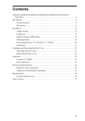
... Installation ...12 Jumper Setting 12 Connectors ...13 Option Switches (DIP Switch 14 Mounting Holes 16 Reconfiguring from 5.25" Model to 3.5" Model 20 Orientation ...21 Attaching and Removing the Dust Cover 22 Attaching the Dust Cover 22 Removing the Dust Cover 24 Operation ...25 Location of 3 LEDs 25 Drive Operation 26 Interface Implementation 29 Supported ATA Commands 29 Supported ATAPI Packet Commands 29 Specifications ...30 Product Specifications 30 Sony Contacts...
... Installation ...12 Jumper Setting 12 Connectors ...13 Option Switches (DIP Switch 14 Mounting Holes 16 Reconfiguring from 5.25" Model to 3.5" Model 20 Orientation ...21 Attaching and Removing the Dust Cover 22 Attaching the Dust Cover 22 Removing the Dust Cover 24 Operation ...25 Location of 3 LEDs 25 Drive Operation 26 Interface Implementation 29 Supported ATA Commands 29 Supported ATAPI Packet Commands 29 Specifications ...30 Product Specifications 30 Sony Contacts...
User Guide
Page 8
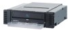
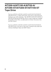
... of Error Correction Code, and other features. AITi200-A/AITi100-A/AITi50-A/ AITi390-ST/AITi200-ST/AITi100-ST Tape Drive The Sony AITi200-A/AITi100-A/AITi50-A/AITi390-ST/AITi200-ST/ AITi100-ST drive is a high capacity data storage device using a standard format called AIT (Advanced Intelligent Tape) and ALDC formats. 8 The Sony AITi200-A/AITi100-A/AITi50-A/AITi390-ST/AITi200-ST/ AITi100-ST drive stores data on tape using Advanced Intelligent tape (AIT) technology...
... of Error Correction Code, and other features. AITi200-A/AITi100-A/AITi50-A/ AITi390-ST/AITi200-ST/AITi100-ST Tape Drive The Sony AITi200-A/AITi100-A/AITi50-A/AITi390-ST/AITi200-ST/ AITi100-ST drive is a high capacity data storage device using a standard format called AIT (Advanced Intelligent Tape) and ALDC formats. 8 The Sony AITi200-A/AITi100-A/AITi50-A/AITi390-ST/AITi200-ST/ AITi100-ST drive stores data on tape using Advanced Intelligent tape (AIT) technology...
User Guide
Page 9
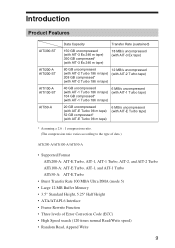
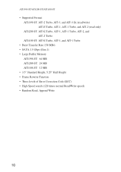
... tape) * Assuming a 2.6 : 1 compression ratio. (The compression ratio varies according to the type of data.) AITi200-A/AITi100-A/AITi50-A • Supported Format AITi200-A: AIT-E Turbo, AIT-1, AIT-1 Turbo, AIT-2, and AIT-2 Turbo AITi100-A: AIT-E Turbo, AIT-1, and AIT-1 Turbo AITi50-A: AIT-E Turbo • Burst Transfer Rate 100 MB/s Ultra DMA (mode 5) • Large 12 MB Buffer Memory • 3.5" Standard Height, 5.25" Half Height • ATA/ATAPI-6 Interface...
... tape) * Assuming a 2.6 : 1 compression ratio. (The compression ratio varies according to the type of data.) AITi200-A/AITi100-A/AITi50-A • Supported Format AITi200-A: AIT-E Turbo, AIT-1, AIT-1 Turbo, AIT-2, and AIT-2 Turbo AITi100-A: AIT-E Turbo, AIT-1, and AIT-1 Turbo AITi50-A: AIT-E Turbo • Burst Transfer Rate 100 MB/s Ultra DMA (mode 5) • Large 12 MB Buffer Memory • 3.5" Standard Height, 5.25" Half Height • ATA/ATAPI-6 Interface...
User Guide
Page 10
AITi390-ST/AITi200-ST/AITi100-ST • Supported Format AITi390-ST: AIT-2 Turbo, AIT-3, and AIT-3 Ex (read/write) AIT-E Turbo, AIT-1, AIT-1 Turbo, and AIT-2 (read only) AITi200-ST: AIT-E Turbo, AIT-1, AIT-1 Turbo, AIT-2, and AIT-2 Turbo AITi100-ST: AIT-E Turbo, AIT-1, and AIT-1 Turbo • Burst Transfer Rate 150 MB/s • SATA 1.5 Gbps (Gen.1) •...ST: 12 MB • 3.5" Standard Height, 5.25" Half Height • Frame Rewrite Function • Three levels of Error Correction Code (ECC) • High Speed search (120 times normal Read/Write speed) • Random Read, Append Write 10
AITi390-ST/AITi200-ST/AITi100-ST • Supported Format AITi390-ST: AIT-2 Turbo, AIT-3, and AIT-3 Ex (read/write) AIT-E Turbo, AIT-1, AIT-1 Turbo, and AIT-2 (read only) AITi200-ST: AIT-E Turbo, AIT-1, AIT-1 Turbo, AIT-2, and AIT-2 Turbo AITi100-ST: AIT-E Turbo, AIT-1, and AIT-1 Turbo • Burst Transfer Rate 150 MB/s • SATA 1.5 Gbps (Gen.1) •...ST: 12 MB • 3.5" Standard Height, 5.25" Half Height • Frame Rewrite Function • Three levels of Error Correction Code (ECC) • High Speed search (120 times normal Read/Write speed) • Random Read, Append Write 10
User Guide
Page 11
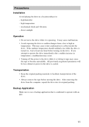
... not move the drive while it is turned on the drive. After removing the drive from a low to operate with an ISV. 11 mechanical shock and vibration - Backup Application Make sure to use a backup application that is operating. It may cause the tape to collect inside the drive. This may occur. • Turning off the power to the drive while it is...
... not move the drive while it is turned on the drive. After removing the drive from a low to operate with an ISV. 11 mechanical shock and vibration - Backup Application Make sure to use a backup application that is operating. It may cause the tape to collect inside the drive. This may occur. • Turning off the power to the drive while it is...
User Guide
Page 12
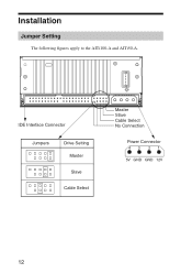
IDE Interface Connector Jumpers Drive Setting Master Slave Cable Select Master Slave Cable Select No Connection Power Connector 43 21 5V GND GND 12V 12 Installation Jumper Setting The following figures apply to the AITi100-A and AITi50-A.
IDE Interface Connector Jumpers Drive Setting Master Slave Cable Select Master Slave Cable Select No Connection Power Connector 43 21 5V GND GND 12V 12 Installation Jumper Setting The following figures apply to the AITi100-A and AITi50-A.

User Guide
Page 14
Option Switches (DIP Switch) DIP Switch Positions Default DIP Switch 1 Drive Mode (OFF) 2 Drive Mode (OFF) 3 Drive Mode (OFF) 4 Drive Mode (OFF) 5 Reserved (OFF) 6 Periodic Cleaning Req (OFF) 7 DC Control (1) (ON) 8 DC Control (2) (OFF) 14
Option Switches (DIP Switch) DIP Switch Positions Default DIP Switch 1 Drive Mode (OFF) 2 Drive Mode (OFF) 3 Drive Mode (OFF) 4 Drive Mode (OFF) 5 Reserved (OFF) 6 Periodic Cleaning Req (OFF) 7 DC Control (1) (ON) 8 DC Control (2) (OFF) 14

User Guide
Page 15
... LED lights, clean the drive with a head cleaning cartridge. Data compression is enabled while position 7 [DC Control (1)] is ON. 15 Cleaning Request Mode Periodic cleaning requests can be selected by DIP switches. Note To maintain the drive in optimum condition in environments affected by a DIP switch. Control by host can be enabled by dust and other contaminants, we recommend keeping cleaning requests enabled. Data Compression Control DIP switch Data compression can be disabled when position...
... LED lights, clean the drive with a head cleaning cartridge. Data compression is enabled while position 7 [DC Control (1)] is ON. 15 Cleaning Request Mode Periodic cleaning requests can be selected by DIP switches. Note To maintain the drive in optimum condition in environments affected by a DIP switch. Control by host can be enabled by dust and other contaminants, we recommend keeping cleaning requests enabled. Data Compression Control DIP switch Data compression can be disabled when position...

User Guide
Page 20
Side Rail (L) Side Rail (R) 20 Reconfiguring from 5.25" Model to 3.5" Model You can reconfigure the 5.25" model to the 3.5" model yourself. 1 Remove the 2 screws for each side rail. 2 Take the side rail off.
Side Rail (L) Side Rail (R) 20 Reconfiguring from 5.25" Model to 3.5" Model You can reconfigure the 5.25" model to the 3.5" model yourself. 1 Remove the 2 screws for each side rail. 2 Take the side rail off.
User Guide
Page 22
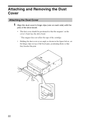
Attaching and Removing the Dust Cover Attaching the Dust Cover 1 Align the dust cover's hinge clips (one on each side) with the pins of the drive bezel. • The dust cover should be positioned so that the magnets* on the cover's back face the drive bezel. * This magnet does not affect the tape of the cartridge. • Holding the dust cover at an angle as shown in the figure below, set the hinge clips on top of the bezel pins, positioning them so that they bracket the pins. 22
Attaching and Removing the Dust Cover Attaching the Dust Cover 1 Align the dust cover's hinge clips (one on each side) with the pins of the drive bezel. • The dust cover should be positioned so that the magnets* on the cover's back face the drive bezel. * This magnet does not affect the tape of the cartridge. • Holding the dust cover at an angle as shown in the figure below, set the hinge clips on top of the bezel pins, positioning them so that they bracket the pins. 22

User Guide
Page 24
Note We recommend that you use the drive with the dust cover. 24 Removing the Dust Cover 1 Open the dust cover. 2 Holding the dust cover at both corners, carefully raise the dust cover. The dust cover hinge clips and drive bezel pins uncouple.
Note We recommend that you use the drive with the dust cover. 24 Removing the Dust Cover 1 Open the dust cover. 2 Holding the dust cover at both corners, carefully raise the dust cover. The dust cover hinge clips and drive bezel pins uncouple.
User Guide
Page 25
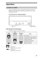
... Independent Tape Access in Progress (others) Independent Independent Cleaning is requested Independent Independent Cleaning is Not Completed Independent Independent Media Error Occurred H/W Error Occurred on Slow 1 pulse (0.9 sec on/0.3 sec off) Fast 1 pulse (0.3 sec on the front panel of 3 LEDs There are defined as follows. Front Panel (for 3.5" Standard Height) Advanced Intelligent Tape LED TAPE MOTION CLEANING REQUEST REPLACE TAPE EJECT button LED Indication for Drive Status The LED...
... Independent Tape Access in Progress (others) Independent Independent Cleaning is requested Independent Independent Cleaning is Not Completed Independent Independent Media Error Occurred H/W Error Occurred on Slow 1 pulse (0.9 sec on/0.3 sec off) Fast 1 pulse (0.3 sec on the front panel of 3 LEDs There are defined as follows. Front Panel (for 3.5" Standard Height) Advanced Intelligent Tape LED TAPE MOTION CLEANING REQUEST REPLACE TAPE EJECT button LED Indication for Drive Status The LED...
User Guide
Page 26
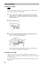
... data cartridge slot. Check that the drive's TAPE MOTION LED, CLEANING REQUEST LED and REPLACE TAPE LED go off the host computer. Drive Operation Loading a Cartridge Note While setting the data cartridge, do not turn off . 2 Open the dust cover. 3 Set the AIT data cartridge orientation as shown here and insert it is rewound and the cartridge ejected from the AITi200-A, AITi100-A, and AITi50-A either in the drive and the TAPE MOTION LED lights. Unloading a Cartridge The cartridge...
... data cartridge slot. Check that the drive's TAPE MOTION LED, CLEANING REQUEST LED and REPLACE TAPE LED go off the host computer. Drive Operation Loading a Cartridge Note While setting the data cartridge, do not turn off . 2 Open the dust cover. 3 Set the AIT data cartridge orientation as shown here and insert it is rewound and the cartridge ejected from the AITi200-A, AITi100-A, and AITi50-A either in the drive and the TAPE MOTION LED lights. Unloading a Cartridge The cartridge...
User Guide
Page 27
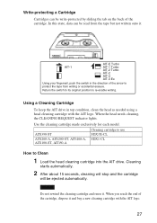
... it . When the head needs cleaning, the CLEANING REQUEST indicator lights. Using a Cleaning Cartridge To keep the AIT drive in the direction of the arrow to protect the tape from the tape but not written onto it. Cleaning starts automatically. 2 After about 15 seconds, cleaning will stop and the cartridge will be ejected automatically. Use the cleaning cartridge made exclusively for each model. When you reach the end of...
... it . When the head needs cleaning, the CLEANING REQUEST indicator lights. Using a Cleaning Cartridge To keep the AIT drive in the direction of the arrow to protect the tape from the tape but not written onto it. Cleaning starts automatically. 2 After about 15 seconds, cleaning will stop and the cartridge will be ejected automatically. Use the cleaning cartridge made exclusively for each model. When you reach the end of...

User Guide
Page 28
Storage Precautions • Keep cartridges in their cases when not in the drives. • Avoid storing cartridges in dusty locations, in direct sunlight, near heaters or air conditioners, or in humid locations. • Do not place cartridges on dashboards or in car storage trays. 28
Storage Precautions • Keep cartridges in their cases when not in the drives. • Avoid storing cartridges in dusty locations, in direct sunlight, near heaters or air conditioners, or in humid locations. • Do not place cartridges on dashboards or in car storage trays. 28
User Guide
Page 29
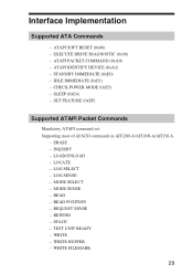
Interface Implementation Supported ATA Commands - EXECUTE DRIVE DIAGNOSTIC (0x90) - IDLE IMMEDIATE (0xE1) - MODE SENSE - READ POSITION - WRITE FILEMARK 29 ATAPI IDENTIFY DEVICE (0xA1) - CHECK POWER MODE (0xE5) - LOCATE - REQUEST SENSE - ERASE - TEST UNIT READY - STANDBY IMMEDIATE (0xE0) - SET FEATURE (0xEF) Supported ATAPI Packet Commands Mandatory ATAPI command set: Supporting most of all SCSI commands in AITi200-A/AITi100-A/AITi50-A. - WRITE - LOG SENSE - SLEEP (0xE6) - READ - REWIND - ATAPI PACKET COMMAND (0xA0) - MODE...
Interface Implementation Supported ATA Commands - EXECUTE DRIVE DIAGNOSTIC (0x90) - IDLE IMMEDIATE (0xE1) - MODE SENSE - READ POSITION - WRITE FILEMARK 29 ATAPI IDENTIFY DEVICE (0xA1) - CHECK POWER MODE (0xE5) - LOCATE - REQUEST SENSE - ERASE - TEST UNIT READY - STANDBY IMMEDIATE (0xE0) - SET FEATURE (0xEF) Supported ATAPI Packet Commands Mandatory ATAPI command set: Supporting most of all SCSI commands in AITi200-A/AITi100-A/AITi50-A. - WRITE - LOG SENSE - SLEEP (0xE6) - READ - REWIND - ATAPI PACKET COMMAND (0xA0) - MODE...
User Guide
Page 32
... 200021 TEL: 86-21-6121-6878 URL: http://www.sony.com.cn/ed/cp/ait/ 32 Ltd.) Enterprise Storage Solutions Dept. 2 International Business Park, #01-10 Tower One, The Strategy, Singapore 609930 TEL: 65-6544-8000 FAX: 65-6544-7390 Sony Corporation of Hong Kong Ltd., Electronic Devices Marketing Hong Kong Computer Peripherals Sales & Marketing Div...
... 200021 TEL: 86-21-6121-6878 URL: http://www.sony.com.cn/ed/cp/ait/ 32 Ltd.) Enterprise Storage Solutions Dept. 2 International Business Park, #01-10 Tower One, The Strategy, Singapore 609930 TEL: 65-6544-8000 FAX: 65-6544-7390 Sony Corporation of Hong Kong Ltd., Electronic Devices Marketing Hong Kong Computer Peripherals Sales & Marketing Div...

User Guide
Page 33
...13-7669 FAX: 02-9870-5864 e-mail: CIC-customerissues@ap.sony.com Sony New Zealand Akoranga Business Park NORTH SHORE, AUCKLAND TEL: 0800-76-6969 FAX: 09-308-9300 e-mail: CIC-customerissues@ap.sony.com Sony Chile Ltda Av. Data Storage Section 5F, 145 Changchun Road, Taipei 104, Taiwan TEL:... FAX: 971-4-8817210 or 8816259 Sony Marketing of Japan Business Solution Dept. Server Solution Marketing Section URL: http://www.sony.co.jp/STORAGE 33 Kennedy 8017, Las Condes, Santiago, Chile TEL: (02) 210-6000 FAX: (02) 210-5417 Sony Taiwan Limited Optical Devices Storage Dept. Rua Inocéncio Tobias...
...13-7669 FAX: 02-9870-5864 e-mail: CIC-customerissues@ap.sony.com Sony New Zealand Akoranga Business Park NORTH SHORE, AUCKLAND TEL: 0800-76-6969 FAX: 09-308-9300 e-mail: CIC-customerissues@ap.sony.com Sony Chile Ltda Av. Data Storage Section 5F, 145 Changchun Road, Taipei 104, Taiwan TEL:... FAX: 971-4-8817210 or 8816259 Sony Marketing of Japan Business Solution Dept. Server Solution Marketing Section URL: http://www.sony.co.jp/STORAGE 33 Kennedy 8017, Las Condes, Santiago, Chile TEL: (02) 210-6000 FAX: (02) 210-5417 Sony Taiwan Limited Optical Devices Storage Dept. Rua Inocéncio Tobias...
