Operating Instructions
Page 1
2-067-134-13(1) AIT Drive Operating Instructions AIT-2 Turbo TAPE DRIVE AITe200-UL/AITe200T-UL AIT-2 TAPE DRIVE AITe130V-UL AIT-1 Turbo TAPE DRIVE AITe100-UL/AITe100T-UL AIT-1 TAPE DRIVE AITe90V-UL ©2004 Sony Corporation
2-067-134-13(1) AIT Drive Operating Instructions AIT-2 Turbo TAPE DRIVE AITe200-UL/AITe200T-UL AIT-2 TAPE DRIVE AITe130V-UL AIT-1 Turbo TAPE DRIVE AITe100-UL/AITe100T-UL AIT-1 TAPE DRIVE AITe90V-UL ©2004 Sony Corporation
Operating Instructions
Page 2
.... All interface cables used in accordance with the limits for help. ATDEA2A (respectively) for Regulatory Compliance Your AITe200-UL or AITe200T-UL is connected. • Consult the dealer or an experienced radio/TV technician for a Class B digital device, pursuant to Part 15 of fire or electric shock, do not open the cabinet. Your AITe130V-UL, AITe100-UL, AITe100T-UL or AITe90V-UL is no...
.... All interface cables used in accordance with the limits for help. ATDEA2A (respectively) for Regulatory Compliance Your AITe200-UL or AITe200T-UL is connected. • Consult the dealer or an experienced radio/TV technician for a Class B digital device, pursuant to Part 15 of fire or electric shock, do not open the cabinet. Your AITe130V-UL, AITe100-UL, AITe100T-UL or AITe90V-UL is no...

Operating Instructions
Page 6
... unit on a bed, sofa, rug or other controls may result in the operating instructions. The unit may expose you to dangerous voltage or other hazards. The slots and openings in the cabinet are specified in damage and will often require extensive work by... ventilation. for service. Accessories - SERVICE Damage Requiring Service - Use only a cart stand tripod, bracket, or table recommended by the manufacturer. Do not use power-line operated units near a bathtub, washbowl, kitchen sink, or laundry tub, in a confined space, such as opening or removing covers may fall...
... unit on a bed, sofa, rug or other controls may result in the operating instructions. The unit may expose you to dangerous voltage or other hazards. The slots and openings in the cabinet are specified in damage and will often require extensive work by... ventilation. for service. Accessories - SERVICE Damage Requiring Service - Use only a cart stand tripod, bracket, or table recommended by the manufacturer. Do not use power-line operated units near a bathtub, washbowl, kitchen sink, or laundry tub, in a confined space, such as opening or removing covers may fall...

Operating Instructions
Page 7
... Compatible Data Cartridges 11 Part Names and Functions 13 Front Panel 13 Rear Panel 14 Supplied Items 15 Interconnections 16 Option Switches (DIP Switch 17 i.LINK 19 How To Use the AIT Drive 21 Cartridge Removal 22 Attaching the Dust Cover 23 Taking Care of the Drives 25 Safety Considerations 25 Avoiding Damage 25 Taking Care of Cartridges 27 Usage Precautions 27 Storage Precautions 27 Cleaning...
... Compatible Data Cartridges 11 Part Names and Functions 13 Front Panel 13 Rear Panel 14 Supplied Items 15 Interconnections 16 Option Switches (DIP Switch 17 i.LINK 19 How To Use the AIT Drive 21 Cartridge Removal 22 Attaching the Dust Cover 23 Taking Care of the Drives 25 Safety Considerations 25 Avoiding Damage 25 Taking Care of Cartridges 27 Usage Precautions 27 Storage Precautions 27 Cleaning...
Operating Instructions
Page 8
... each part. How To Use This Guide This guide describes how to use and care for future reference. Please read it carefully before using the drives and save it on, and how to Use this manual. 8 How to insert and remove cartridges. Chapter 2 Preparation Describes the necessary connections between the drives and the host computer. Chapter 4 Care and Maintenance Describes how to take care of interface...
... each part. How To Use This Guide This guide describes how to use and care for future reference. Please read it carefully before using the drives and save it on, and how to Use this manual. 8 How to insert and remove cartridges. Chapter 2 Preparation Describes the necessary connections between the drives and the host computer. Chapter 4 Care and Maintenance Describes how to take care of interface...
Operating Instructions
Page 9
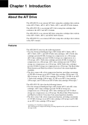
... Third Level Error Correction Code ensure high data reliability. • The drive comes with a data compression function, providing a maximum of 130 GB of storage on an AIT-2 data cartridge (230-m tape), 104 GB on an AIT1 Turbo data cartridge (186-m tape), 91 GB on an AIT-1 data cartridge (230-m tape), and 52 GB on an AIT-1 data cartridge (230-m tape).*1 *1 Assuming a 2.6:1 hardware compression ratio. Chapter 1 Introduction About the AIT Drive Features The AITe200-UL is an external AIT drive using data cartridges that conform...
... Third Level Error Correction Code ensure high data reliability. • The drive comes with a data compression function, providing a maximum of 130 GB of storage on an AIT-2 data cartridge (230-m tape), 104 GB on an AIT1 Turbo data cartridge (186-m tape), 91 GB on an AIT-1 data cartridge (230-m tape), and 52 GB on an AIT-1 data cartridge (230-m tape).*1 *1 Assuming a 2.6:1 hardware compression ratio. Chapter 1 Introduction About the AIT Drive Features The AITe200-UL is an external AIT drive using data cartridges that conform...
Operating Instructions
Page 10
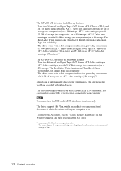
... storage (no compression) on a 98-m tape. The drive is automatically checked for compression. Note You cannot use the USB and i.LINK interfaces simultaneously. You can therefore connect the drive to either connector to your computer is on an AIT-1 data cartridge (230-m tape).*1 Stored data is equipped with other devices. AIT-E Turbo data cartridges provide 20 GB of compression during recording depends on the Windows taskbar, and then disconnect the AIT drive. *1 Assuming a 2.6:1 hardware compression...
... storage (no compression) on a 98-m tape. The drive is automatically checked for compression. Note You cannot use the USB and i.LINK interfaces simultaneously. You can therefore connect the drive to either connector to your computer is on an AIT-1 data cartridge (230-m tape).*1 Stored data is equipped with other devices. AIT-E Turbo data cartridges provide 20 GB of compression during recording depends on the Windows taskbar, and then disconnect the AIT drive. *1 Assuming a 2.6:1 hardware compression...
Operating Instructions
Page 11
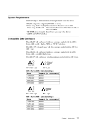
... requirements to use the drives. • PC/AT-compatible computer (300 MHz or faster) • When using the NT backup:Windows XP or Windows Server 2003 When using the 1Safe™: Windows XP, Windows 2000, Windows Me, or Windows 98 SE • CD-ROM drives (to install the software necessary to the drives) • i.LINK and/or USB interface Compatible Data Cartridges The AITe200-UL can be used with data cartridges marked with the AIT-1 Turbo, AIT-1, or AIT-E Turbo...
... requirements to use the drives. • PC/AT-compatible computer (300 MHz or faster) • When using the NT backup:Windows XP or Windows Server 2003 When using the 1Safe™: Windows XP, Windows 2000, Windows Me, or Windows 98 SE • CD-ROM drives (to install the software necessary to the drives) • i.LINK and/or USB interface Compatible Data Cartridges The AITe200-UL can be used with data cartridges marked with the AIT-1 Turbo, AIT-1, or AIT-E Turbo...

Operating Instructions
Page 13
... Part Names and Functions Front Panel 1 2 Advanced Intelligent Tape 34 5 6 1 AIT Data Cartridge Receptacle See page 21 to 22 for information on inserting and removing a AIT data cartridge. 2 POWER Indicator Lights while the drive is Not Completed Independent Independent Media Error Occurred H/W Error Occurred on Slow 1 pulse (0.9 sec on/0.3 sec off) Fast 1 pulse (0.3 sec on . 3 Dust Cover This cover protects the AIT data cartridge receptacle. 4 LED Indication for Drive Status The LED...
... Part Names and Functions Front Panel 1 2 Advanced Intelligent Tape 34 5 6 1 AIT Data Cartridge Receptacle See page 21 to 22 for information on inserting and removing a AIT data cartridge. 2 POWER Indicator Lights while the drive is Not Completed Independent Independent Media Error Occurred H/W Error Occurred on Slow 1 pulse (0.9 sec on/0.3 sec off) Fast 1 pulse (0.3 sec on . 3 Dust Cover This cover protects the AIT data cartridge receptacle. 4 LED Indication for Drive Status The LED...

Operating Instructions
Page 14
Rear Panel 5 EJECT Button Push to remove a data cartridge from the drive. 6 POWER Switch Press to turn the drive on or off. 1 23 4 1 AC IN Connector Connect the supplied power cable here. 2 i.LINK Connectors ( ) Connects to the i.LINK connector of the host computer. 3 USB Connector ( ) Connects to the USB connector of the host computer or a USB hub. 4 Cooling Fan 14 Chapter 1 Introduction
Rear Panel 5 EJECT Button Push to remove a data cartridge from the drive. 6 POWER Switch Press to turn the drive on or off. 1 23 4 1 AC IN Connector Connect the supplied power cable here. 2 i.LINK Connectors ( ) Connects to the i.LINK connector of the host computer. 3 USB Connector ( ) Connects to the USB connector of the host computer or a USB hub. 4 Cooling Fan 14 Chapter 1 Introduction
Operating Instructions
Page 15
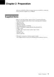
.../or damaged. • AIT Drive Unit • Quick start guide • AIT Data Cartridge • Operating instructions CD-ROM • 1Safe™ CD-ROM (excluding AITe200-UL/AITe200T-UL) • USB 2.0 cable • i.LINK cables (6-pin to 6-pin, 6-pin to 4-pin, 1 each) • Power cable • Warranty card* • Safety regulations *Warranty coverage may vary from region to region. *The supplied items are accounted for, connect the drives to the host computer...
.../or damaged. • AIT Drive Unit • Quick start guide • AIT Data Cartridge • Operating instructions CD-ROM • 1Safe™ CD-ROM (excluding AITe200-UL/AITe200T-UL) • USB 2.0 cable • i.LINK cables (6-pin to 6-pin, 6-pin to 4-pin, 1 each) • Power cable • Warranty card* • Safety regulations *Warranty coverage may vary from region to region. *The supplied items are accounted for, connect the drives to the host computer...

Operating Instructions
Page 17
... Control (1) (ON) 8 DC Control (2) (OFF) 17 Chapter 2 Preparation Once the DIP switch settings have been changed, replace the access cover using a slotted screwdriver. Option Switches (DIP Switch) Remove the two slotted screws by using the two original slotted screws provided. DIP Switch Access CAUTION Before removing the access cover to change the DIP switch settings. (Refer to change DIP switch settings on the drive, turn off the computer and disconnect the power cord from the unit. Remove...
... Control (1) (ON) 8 DC Control (2) (OFF) 17 Chapter 2 Preparation Once the DIP switch settings have been changed, replace the access cover using a slotted screwdriver. Option Switches (DIP Switch) Remove the two slotted screws by using the two original slotted screws provided. DIP Switch Access CAUTION Before removing the access cover to change the DIP switch settings. (Refer to change DIP switch settings on the drive, turn off the computer and disconnect the power cord from the unit. Remove...
Operating Instructions
Page 18
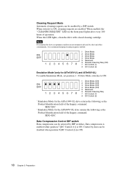
... switch 6 is ON. When this LED lights, clean the drive with a head cleaning cartridge. Data compression is enabled while position 7 [DC Control (1)] is ON, cleaning requests are enabled. SDX-520C * Emulation Mode for the AITe90V-UL drive returns the following as the Product Identification field of operation. Cleaning Request Mode Automatic cleaning requests can be selected by DIP switches. SDX-420C Data Compression Control DIP switch Data compression can be disabled when position 8 [DC Control...
... switch 6 is ON. When this LED lights, clean the drive with a head cleaning cartridge. Data compression is enabled while position 7 [DC Control (1)] is ON, cleaning requests are enabled. SDX-520C * Emulation Mode for the AITe90V-UL drive returns the following as the Product Identification field of operation. Cleaning Request Mode Automatic cleaning requests can be selected by DIP switches. SDX-420C Data Compression Control DIP switch Data compression can be disabled when position 8 [DC Control...

Operating Instructions
Page 19
... characteristics and specifications of the individual device. Use of i.LINK is a digital serial interface that device can be controlled, depends on the features and specifications of devices in any sequence. This means that devices can be connected in the future, providing even more options for control and data transfer. i.LINK cable Data transfer and control are possible even when two i.LINK devices are connected in series, control and data transfer...
... characteristics and specifications of the individual device. Use of i.LINK is a digital serial interface that device can be controlled, depends on the features and specifications of devices in any sequence. This means that devices can be connected in the future, providing even more options for control and data transfer. i.LINK cable Data transfer and control are possible even when two i.LINK devices are connected in series, control and data transfer...

Operating Instructions
Page 21
... the drive unit during operation, to handle data cartridges. The POWER indicator should light, and the TAPE MOTION, CLEANING REQUEST, and REPLACE TAPE indicators should blink as the self-test is performed. 2 When the three indicators stop blinking, open the dust cover and insert a data cartridge as shown below. While reading or writing, the TAPE MOTION indicator blinks. 4 Close the dust cover. How To Use the AIT Drive 1 Press the POWER switch on...
... the drive unit during operation, to handle data cartridges. The POWER indicator should light, and the TAPE MOTION, CLEANING REQUEST, and REPLACE TAPE indicators should blink as the self-test is performed. 2 When the three indicators stop blinking, open the dust cover and insert a data cartridge as shown below. While reading or writing, the TAPE MOTION indicator blinks. 4 Close the dust cover. How To Use the AIT Drive 1 Press the POWER switch on...

Operating Instructions
Page 27
.... • Do not place cartridges on the face of the arrow M to the write-protect position. Do not open or dismantle it. • The write-protect switch on dashboards or in the direction of the cartridge is inserted into the drives. AIT-1 Lid AIT-2 Turbo, AIT-2, AIT-1 Turbo, AIT-E Turbo Lid Using your fingernail, push the switch in car storage trays. 27 Chapter 4 Care...
.... • Do not place cartridges on the face of the arrow M to the write-protect position. Do not open or dismantle it. • The write-protect switch on dashboards or in the direction of the cartridge is inserted into the drives. AIT-1 Lid AIT-2 Turbo, AIT-2, AIT-1 Turbo, AIT-E Turbo Lid Using your fingernail, push the switch in car storage trays. 27 Chapter 4 Care...

Operating Instructions
Page 29
Appendix Specifications AITe200-UL ■ Performance Storage Capacity Data Transfer Rate (TAPE) Burst Data Transfer Rate Bit Error Rate 80 GB uncompressed (with 186 m AIT-2 Turbo data cartridge) 208 GB compressed (with 186 m AIT-2 Turbo data cartridge*1) 12 MB/s uncompressed (with AIT-2 Turbo data cartridge) 480 Mbps maximum (USB) 400 Mbps maximum (i.LINK) less than 10-17 ■ Operating Environment Operating Non-operating Temperature: 10 °C to 35 °C (∆T
Appendix Specifications AITe200-UL ■ Performance Storage Capacity Data Transfer Rate (TAPE) Burst Data Transfer Rate Bit Error Rate 80 GB uncompressed (with 186 m AIT-2 Turbo data cartridge) 208 GB compressed (with 186 m AIT-2 Turbo data cartridge*1) 12 MB/s uncompressed (with AIT-2 Turbo data cartridge) 480 Mbps maximum (USB) 400 Mbps maximum (i.LINK) less than 10-17 ■ Operating Environment Operating Non-operating Temperature: 10 °C to 35 °C (∆T
Operating Instructions
Page 30
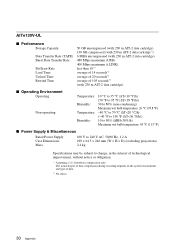
AITe130V-UL ■ Performance Storage Capacity Data Transfer Rate (TAPE) Burst Data Transfer Rate Bit Error Rate Load Time Unload Time Rewind Time 50 GB uncompressed (with 230 m AIT-2 data cartridge) 130 GB compressed (with 230 m AIT-2 data cartridge*1) 6 MB/s uncompressed (with 230 m AIT-2 data cartridge) 480 Mbps maximum (USB) 400 Mbps maximum (i.LINK) less than 10-17 average of 14 seconds*2 average of 20 seconds*2 average of 105 seconds*2 (with 230 m AIT-2 data cartridge) ■ Operating Environment Operating Non-operating Temperature: 10 °C to 35 °C (∆T
AITe130V-UL ■ Performance Storage Capacity Data Transfer Rate (TAPE) Burst Data Transfer Rate Bit Error Rate Load Time Unload Time Rewind Time 50 GB uncompressed (with 230 m AIT-2 data cartridge) 130 GB compressed (with 230 m AIT-2 data cartridge*1) 6 MB/s uncompressed (with 230 m AIT-2 data cartridge) 480 Mbps maximum (USB) 400 Mbps maximum (i.LINK) less than 10-17 average of 14 seconds*2 average of 20 seconds*2 average of 105 seconds*2 (with 230 m AIT-2 data cartridge) ■ Operating Environment Operating Non-operating Temperature: 10 °C to 35 °C (∆T
Operating Instructions
Page 31
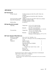
AITe100-UL ■ Performance Storage Capacity Data Transfer Rate (TAPE) Burst Data Transfer Rate Bit Error Rate 40 GB uncompressed (with 186 m AIT-1 Turbo data cartridge) 104 GB compressed (with 186 m AIT-1 Turbo data cartridge*1) 6 MB/s uncompressed (with AIT-1 Turbo data cartridge) 480 Mbps maximum (USB) 400 Mbps maximum (i.LINK) less than 10-17 ■ Operating Environment Operating Non-operating Temperature: 10 °C to 35 °C (∆T
AITe100-UL ■ Performance Storage Capacity Data Transfer Rate (TAPE) Burst Data Transfer Rate Bit Error Rate 40 GB uncompressed (with 186 m AIT-1 Turbo data cartridge) 104 GB compressed (with 186 m AIT-1 Turbo data cartridge*1) 6 MB/s uncompressed (with AIT-1 Turbo data cartridge) 480 Mbps maximum (USB) 400 Mbps maximum (i.LINK) less than 10-17 ■ Operating Environment Operating Non-operating Temperature: 10 °C to 35 °C (∆T
Operating Instructions
Page 32
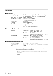
AITe90V-UL ■ Performance Storage Capacity Data Transfer Rate (TAPE) Burst Data Transfer Rate Bit Error Rate Load Time Unload Time Rewind Time 35 GB uncompressed (with 230 m AIT-1 data cartridge) 91 GB compressed (with 230 m AIT-1 data cartridge*1) 4 MB/s uncompressed 480 Mbps maximum (USB) 400 Mbps maximum (i.LINK) less than 10-17 average of 14 seconds*2 average of 20 seconds*2 average of 105 seconds*2 (with 230 m AIT-1 data cartridge) ■ Operating Environment Operating Non-operating Temperature: 10 °C to 35 °C (∆T
AITe90V-UL ■ Performance Storage Capacity Data Transfer Rate (TAPE) Burst Data Transfer Rate Bit Error Rate Load Time Unload Time Rewind Time 35 GB uncompressed (with 230 m AIT-1 data cartridge) 91 GB compressed (with 230 m AIT-1 data cartridge*1) 4 MB/s uncompressed 480 Mbps maximum (USB) 400 Mbps maximum (i.LINK) less than 10-17 average of 14 seconds*2 average of 20 seconds*2 average of 105 seconds*2 (with 230 m AIT-1 data cartridge) ■ Operating Environment Operating Non-operating Temperature: 10 °C to 35 °C (∆T
