Service Manual
Page 17
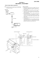
... At this set vertically as mentioned above. 7. MDX-C7970), load a disc magazine, and place the set to B. SECTION 4 MECHANICAL ADJUSTMENT CDX-757MX • Elevator Height (Address) Adjustment Note: This adjustments is finished, check all operations from 5 to 10 with the set horizontally and make ...same adjustment as shown below , adjust the following. 5. Connection: power supply (DC 14.4 V) + GND master unit BUS cable Adjustment Method: 1. Press the DISC button on the master unit so that the elevator shaft positions in a range...
... At this set vertically as mentioned above. 7. MDX-C7970), load a disc magazine, and place the set to B. SECTION 4 MECHANICAL ADJUSTMENT CDX-757MX • Elevator Height (Address) Adjustment Note: This adjustments is finished, check all operations from 5 to 10 with the set horizontally and make ...same adjustment as shown below , adjust the following. 5. Connection: power supply (DC 14.4 V) + GND master unit BUS cable Adjustment Method: 1. Press the DISC button on the master unit so that the elevator shaft positions in a range...
Service Manual
Page 18
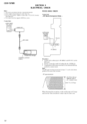
...disc "YEDS-18" parts code: 3-702-101-01, but only when indicated. 4. Note: Clear RF signal waveform means that supports SONY bus system. Be sure to AC range and raise the vertical sensitivity so that oscilloscope waveform is clear and check RF sig- nal level...9674;" can be easily seen. 18 Connection: power supply (DC 14.4 V) + GND master unit oscilloscope (AC range) BUS cable + - FOCUS BIAS CHECK Connection: - Connect the oscilloscope to TP (RFAC) and TP (VC) on the RF board. 2. RF Board (Component Side) - CDX-757MX SECTION 5 ELECTRICAL CHECK Note: 1. Confirm that ...
...disc "YEDS-18" parts code: 3-702-101-01, but only when indicated. 4. Note: Clear RF signal waveform means that supports SONY bus system. Be sure to AC range and raise the vertical sensitivity so that oscilloscope waveform is clear and check RF sig- nal level...9674;" can be easily seen. 18 Connection: power supply (DC 14.4 V) + GND master unit oscilloscope (AC range) BUS cable + - FOCUS BIAS CHECK Connection: - Connect the oscilloscope to TP (RFAC) and TP (VC) on the RF board. 2. RF Board (Component Side) - CDX-757MX SECTION 5 ELECTRICAL CHECK Note: 1. Confirm that ...


