User Guide
Page 1
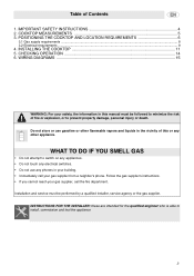
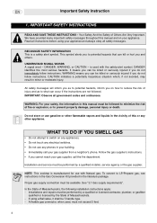
... test the appliance 3 WIRING DIAGRAMS ...15 WARNING: For your building. • Immediately call the fire department. INSTRUCTIONS FOR THE INSTALLER: these are intended for the qualified engineer who is able to switch on any appliances. • Do not touch any electrical switches. • Do not use gasoline or other appliance. POSITIONING THE COOKTOP AND LOCATION REQUIREMENTS 6 3.1 Gas supply requirements ...8 3.2 Electrical requirements ...9 4. Table of fire...
... test the appliance 3 WIRING DIAGRAMS ...15 WARNING: For your building. • Immediately call the fire department. INSTRUCTIONS FOR THE INSTALLER: these are intended for the qualified engineer who is able to switch on any appliances. • Do not touch any electrical switches. • Do not use gasoline or other appliance. POSITIONING THE COOKTOP AND LOCATION REQUIREMENTS 6 3.1 Gas supply requirements ...8 3.2 Electrical requirements ...9 4. Table of fire...
User Guide
Page 2
..., call your appliance and always obey all government codes and ordinances. A flexible gas connector, when used with Natural gas. is used , must be T-handle type. - Follow the gas supplier's instructions. • lf you and others. To convert to switch on any appliances. • Do not touch any electrical switches. • Do not use any other flammable vapors and liquids in your building...
..., call your appliance and always obey all government codes and ordinances. A flexible gas connector, when used with Natural gas. is used , must be T-handle type. - Follow the gas supplier's instructions. • lf you and others. To convert to switch on any appliances. • Do not touch any electrical switches. • Do not use any other flammable vapors and liquids in your building...
User Guide
Page 3
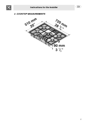
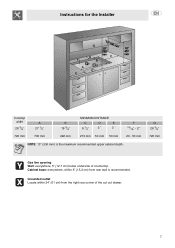
COOKTOP MEASUREMENTS 5 Instructions for the Installer 2.
COOKTOP MEASUREMENTS 5 Instructions for the Installer 2.

User Guide
Page 4
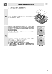
... minimum clearances. - The model/serial rating plate is an integral part of the cooktop burner box. - Given dimensions are shown must be kept handy for the Installer 3. See "3.1 Gas supply requirements" section To prevent accidents or ruining the mobile components of the appliance, the following operation requires building and/or carpentry work and must be available. Grounded electrical supply is the installer's responsibility to the figure below : 1 Remove...
... minimum clearances. - The model/serial rating plate is an integral part of the cooktop burner box. - Given dimensions are shown must be kept handy for the Installer 3. See "3.1 Gas supply requirements" section To prevent accidents or ruining the mobile components of the appliance, the following operation requires building and/or carpentry work and must be available. Grounded electrical supply is the installer's responsibility to the figure below : 1 Remove...
User Guide
Page 5
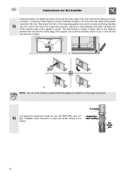
G 28 3/8" 720 mm Gas line opening Wall: everywhere, 5" (12.7 cm) below underside of the cut out drawer. 7 Grounded outlet Locate within 6" (15.2 cm) from the right rear corner of countertop. Instructions for the Installer Cooktop widht 28 3/8" 720 mm A 27 1/2" 700 mm B 19 3/8" 492 mm MINIMUM DISTANCE C D E 8 1/4" 2 " 2 " 210 mm 50 mm 50 mm F 13/16" - 2 " 20 - 50 mm NOTE: 13" (330 mm) is recommended. Cabinet base: everywhere, within 24" (61 cm) from rear wall is the maximum recommended upper cabinet depth.
G 28 3/8" 720 mm Gas line opening Wall: everywhere, 5" (12.7 cm) below underside of the cut out drawer. 7 Grounded outlet Locate within 6" (15.2 cm) from the right rear corner of countertop. Instructions for the Installer Cooktop widht 28 3/8" 720 mm A 27 1/2" 700 mm B 19 3/8" 492 mm MINIMUM DISTANCE C D E 8 1/4" 2 " 2 " 210 mm 50 mm 50 mm F 13/16" - 2 " 20 - 50 mm NOTE: 13" (330 mm) is recommended. Cabinet base: everywhere, within 24" (61 cm) from rear wall is the maximum recommended upper cabinet depth.
User Guide
Page 6
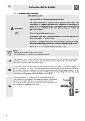
... in a location that allows for connecting this cooktop to shutoff valve. The valve is necessary for turning the gas to the cooktop. Use a new AGA- Examples of qualified technicians include licensed heating personnel, authorized gas company personnel, and authorized service personnel. - If local codes permit, a flexible metal appliance connector with American National Standard, National Fuel Gas Code ANSI Z223.1 latest edition or...
... in a location that allows for connecting this cooktop to shutoff valve. The valve is necessary for turning the gas to the cooktop. Use a new AGA- Examples of qualified technicians include licensed heating personnel, authorized gas company personnel, and authorized service personnel. - If local codes permit, a flexible metal appliance connector with American National Standard, National Fuel Gas Code ANSI Z223.1 latest edition or...
User Guide
Page 7
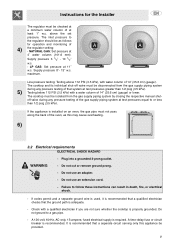
... may cause overheating. 6) 3.2 Electrical requirements ELECTRICAL SHOCK HAZARD - Plug into a grounded 3-prong outlet. Do not use an extension cord. - A 120-volt, 60-Hz, AC-only, 15-ampere, fused electrical supply is adequate. - It is installed on an oven, the gas pipe must be provided. 9 LP GAS: Set pressure at 4" water column (101.6 mm). lf codes permit and a separate ground wire is used, it is recommended that...
... may cause overheating. 6) 3.2 Electrical requirements ELECTRICAL SHOCK HAZARD - Plug into a grounded 3-prong outlet. Do not use an extension cord. - A 120-volt, 60-Hz, AC-only, 15-ampere, fused electrical supply is adequate. - It is installed on an oven, the gas pipe must be provided. 9 LP GAS: Set pressure at 4" water column (101.6 mm). lf codes permit and a separate ground wire is used, it is recommended that...
User Guide
Page 8
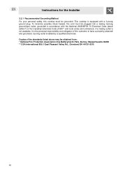
Copies of the customer to have a properly polarized and grounded, 3-prong outlet installed by a qualified electrician. Instructions for the Installer 3.2.1 Recommended Grounding Method For your personal safety, this cooktop must be plugged into a mating 3-prong ground-type outlet, grounded in accordance...ANSI/NFPA 70 Electrical Code (latest edition*) or the Canadian Electrical Code (CSA)** and local codes and ordinances. This cooktop is the personal responsibility and obligation of the standards listed above may be grounded. To minimize possible shock hazard, the cord must be ...
Copies of the customer to have a properly polarized and grounded, 3-prong outlet installed by a qualified electrician. Instructions for the Installer 3.2.1 Recommended Grounding Method For your personal safety, this cooktop must be plugged into a mating 3-prong ground-type outlet, grounded in accordance...ANSI/NFPA 70 Electrical Code (latest edition*) or the Canadian Electrical Code (CSA)** and local codes and ordinances. This cooktop is the personal responsibility and obligation of the standards listed above may be grounded. To minimize possible shock hazard, the cord must be ...
User Guide
Page 9
... an arrow printed on the pressure regulator 2 Turn it to the cooktop connector. 11 USE A SOAPY SOLUTION TO CHECK FOR PROPER TIGHTNESS. Connection to the gas mains may be connected to the part where LP is printed 3 Re-tighten it and lock the pins in force. Instructions for LP operation of the cooktop: 1 Unscrew cap A on the back of the energy regulator...
... an arrow printed on the pressure regulator 2 Turn it to the cooktop connector. 11 USE A SOAPY SOLUTION TO CHECK FOR PROPER TIGHTNESS. Connection to the gas mains may be connected to the part where LP is printed 3 Re-tighten it and lock the pins in force. Instructions for LP operation of the cooktop: 1 Unscrew cap A on the back of the energy regulator...
User Guide
Page 10
... edge of the gasket A (pic.2). Use pipe-joint compound made for the Installer Carefully position the gasket provided all of the brackets supplied with NATURAL and L.P. 4) gas. Instructions for use the screws and fixing brackets 3) (fig. 3) to secure the hob to the supporting structure, adjusting it until the hob has been set in place. 1) 2) 3) NOTE: Use all around the outer edge of...
... edge of the gasket A (pic.2). Use pipe-joint compound made for the Installer Carefully position the gasket provided all of the brackets supplied with NATURAL and L.P. 4) gas. Instructions for use the screws and fixing brackets 3) (fig. 3) to secure the hob to the supporting structure, adjusting it until the hob has been set in place. 1) 2) 3) NOTE: Use all around the outer edge of...
User Guide
Page 11
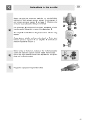
...-spreader holes A are aligned with NATURAL GAS and L.P. If flexible metal conductor is used, be fitted on the burners, make sure that the flame-spreader crowns and respective caps are properly fitted in force, 5) inserting gasket B (supplied) between fitting A ... E. Instructions for the Installer Always use pipe-joint compound made for use with the ignition plugs and the thermocouples. 7) Plug power supply cord into grounded outlet. 13 GAS between pressure regulator D and adaptator C and between pressure regulator D and pipe E. Before turning on the gas connection A before...
...-spreader holes A are aligned with NATURAL GAS and L.P. If flexible metal conductor is used, be fitted on the burners, make sure that the flame-spreader crowns and respective caps are properly fitted in force, 5) inserting gasket B (supplied) between fitting A ... E. Instructions for the Installer Always use pipe-joint compound made for use with the ignition plugs and the thermocouples. 7) Plug power supply cord into grounded outlet. 13 GAS between pressure regulator D and adaptator C and between pressure regulator D and pipe E. Before turning on the gas connection A before...
User Guide
Page 12
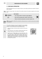
... proper operation. 1) Check for proper operation only after top assembly has been completed as and you have checked to the appliance. WARNING FIRE HAZARD - Instructions for proper tightness. - Check that the power supply cord is pressed and turned to the 2) low flame symbol ( ), the entire crown should light. 3 lf burners do not light properly, turn the control knob to the support structure...
... proper operation. 1) Check for proper operation only after top assembly has been completed as and you have checked to the appliance. WARNING FIRE HAZARD - Instructions for proper tightness. - Check that the power supply cord is pressed and turned to the 2) low flame symbol ( ), the entire crown should light. 3 lf burners do not light properly, turn the control knob to the support structure...
User Guide
Page 13
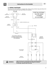
WIRING DIAGRAMS The power cord on this appliance is equipped with a threee pronge polarized plug (grounding) which mates with standard three pronged (grounding) wall receptacles. Wiring errors can cause improper and dangerous operation. WARNING Label all wires prior to disconnection when servicing controls. Verify proper operation after servicing. 15 Instructions for the Installer 6.
WIRING DIAGRAMS The power cord on this appliance is equipped with a threee pronge polarized plug (grounding) which mates with standard three pronged (grounding) wall receptacles. Wiring errors can cause improper and dangerous operation. WARNING Label all wires prior to disconnection when servicing controls. Verify proper operation after servicing. 15 Instructions for the Installer 6.


