
Instruction Manual
Page 2
... 6 3.2 Machine Installation 7 3.3 Lubrication and Oil Drainage 9 3.4 Fill Silicon Oil to Reservoir 10 3.5 Needle Attachment (or Replacement) 10 3.6 Replacing Upper and Lower Knife 11 3.7 Machine Threading 12 3.8 Thread Tension Adjustment 13 3.9 Presser foot pressure 14 3.10 Adjusting the Differential Feed Rate 14 3.11 Stitch Length Adjustment 15 3.12 Parts Relation and Timing 16...
... 6 3.2 Machine Installation 7 3.3 Lubrication and Oil Drainage 9 3.4 Fill Silicon Oil to Reservoir 10 3.5 Needle Attachment (or Replacement) 10 3.6 Replacing Upper and Lower Knife 11 3.7 Machine Threading 12 3.8 Thread Tension Adjustment 13 3.9 Presser foot pressure 14 3.10 Adjusting the Differential Feed Rate 14 3.11 Stitch Length Adjustment 15 3.12 Parts Relation and Timing 16...

Instruction Manual
Page 3
... 24 6.3 Machine Cover Components (2) 26 6.4 Crank Shaft Drive Components 28 6.5 Thread Tension Components 30 6.6 Thread Guide and Thread Take-up Components (1) 32 6.7 Thread Guide and Thread Take-up Components (2) 34 6.8 Thread Guide and Thread Take-up Components (3) 36 6.9 Needle Bar Components (1) 38 6.10 Needle Bar...Lubrication Components (2) 62 6.22 Silicon Oil Reservoir Components 64 6.23 Exclusive Parts List for 321K series 66 6.24 Thread Stand Components 68 6.25 Accessories 70 6.26 Machine Support Plate For Semi-Submerged Components 72 6.27 Specific Parts...
... 24 6.3 Machine Cover Components (2) 26 6.4 Crank Shaft Drive Components 28 6.5 Thread Tension Components 30 6.6 Thread Guide and Thread Take-up Components (1) 32 6.7 Thread Guide and Thread Take-up Components (2) 34 6.8 Thread Guide and Thread Take-up Components (3) 36 6.9 Needle Bar Components (1) 38 6.10 Needle Bar...Lubrication Components (2) 62 6.22 Silicon Oil Reservoir Components 64 6.23 Exclusive Parts List for 321K series 66 6.24 Thread Stand Components 68 6.25 Accessories 70 6.26 Machine Support Plate For Semi-Submerged Components 72 6.27 Specific Parts...

Instruction Manual
Page 4
... the product. Read with the proper electric cable and connectors, and also the adequate grounding. • The machine should only be followed. Singer will not be held responsible for any electric device is damaged, the machine should be immediately stopped. • Before starting the machine in ... equipment should be used while running the machine. • Turn off or unplug the machine when the following situations arise: • Passing the thread by the needle or replacing the bobbin or looper. • Replacing the needle, presser foot, throat plate, feed dog and sliding plate. &#...
... the product. Read with the proper electric cable and connectors, and also the adequate grounding. • The machine should only be followed. Singer will not be held responsible for any electric device is damaged, the machine should be immediately stopped. • Before starting the machine in ... equipment should be used while running the machine. • Turn off or unplug the machine when the following situations arise: • Passing the thread by the needle or replacing the bobbin or looper. • Replacing the needle, presser foot, throat plate, feed dog and sliding plate. &#...
Instruction Manual
Page 5
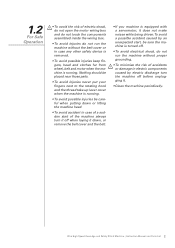
... Parts List 2 Nothing should be placed near those parts. • To avoid injuries never put your fingers next to the rotating hook and the thread take-up lever cover when the machine is running . 1.2 For Safe Operation • To avoid the risk of electric shock, do not open the motor...
... Parts List 2 Nothing should be placed near those parts. • To avoid injuries never put your fingers next to the rotating hook and the thread take-up lever cover when the machine is running . 1.2 For Safe Operation • To avoid the risk of electric shock, do not open the motor...
Instruction Manual
Page 7
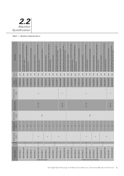
... Presser Foot Lift [mm] Singer Needle Cat Speed [spm] Application 321D-131M-04 4 321D-131M-04 / KS 4 13 - 321D-132M-015 1.5 321D-134M-04 4 6120-06 75/11 6120-06 75/11 6120-06 65/9 6120-06 75/11 8500 Three-thread overlock machine 8500 8500 Three-thread overlock machine with vertical chain...
... Presser Foot Lift [mm] Singer Needle Cat Speed [spm] Application 321D-131M-04 4 321D-131M-04 / KS 4 13 - 321D-132M-015 1.5 321D-134M-04 4 6120-06 75/11 6120-06 75/11 6120-06 65/9 6120-06 75/11 8500 Three-thread overlock machine 8500 8500 Three-thread overlock machine with vertical chain...
Instruction Manual
Page 11
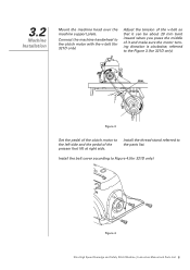
3.2 Machine Installation Mount the machine head over the machine support plate. Install the thread stand referred to the Figure 3.(for 321D only) Figure 4 Ultra High Speed Overedge and Safety Stitch Machine | Instruction Manual and Parts List 8 Connect the machine ...
3.2 Machine Installation Mount the machine head over the machine support plate. Install the thread stand referred to the Figure 3.(for 321D only) Figure 4 Ultra High Speed Overedge and Safety Stitch Machine | Instruction Manual and Parts List 8 Connect the machine ...

Instruction Manual
Page 13
...;ll the device with the Allen key wrench in order to the proper depth. Insert the needle to prevent needle thread breakage and fabric damage. Figure 8 3.5 Needle Attachment (or Replacement) Use only Singer's Cat. 6120 needles Loosen screw '1' as indicated on Figure 8. Figure 9 (a) OK! Figure 9 (b) Figure 10 Ultra High Speed Overedge and...
...;ll the device with the Allen key wrench in order to the proper depth. Insert the needle to prevent needle thread breakage and fabric damage. Figure 8 3.5 Needle Attachment (or Replacement) Use only Singer's Cat. 6120 needles Loosen screw '1' as indicated on Figure 8. Figure 9 (a) OK! Figure 9 (b) Figure 10 Ultra High Speed Overedge and...

Instruction Manual
Page 14
... anb lower knives by turning the handwheel. 8 3 4 7 2 1 5 4 6 Figure 11 Replacing the lower knife 1. Loosen screw '1'. 3.6 Replacing Upper and Lower Knife Replacing the upper knife 1. Place a thread between the upper and lower knives. Tighten screw '1' temporarily. 2. Install a new knife by referring to "Replacing the upper knife" procedures 3 and 4. To install a new upper...
... anb lower knives by turning the handwheel. 8 3 4 7 2 1 5 4 6 Figure 11 Replacing the lower knife 1. Loosen screw '1'. 3.6 Replacing Upper and Lower Knife Replacing the upper knife 1. Place a thread between the upper and lower knives. Tighten screw '1' temporarily. 2. Install a new knife by referring to "Replacing the upper knife" procedures 3 and 4. To install a new upper...
Instruction Manual
Page 15
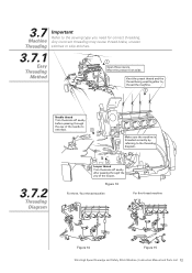
... three covers. Move the presser foot aside. Knot the preset thread and the thread being used together to thread the machine. 2 Needle thread Trim the knots off neatly after passing through the eye of the looper. 3.7 Machine Threading Important Refer to the threading diagram. 3.7.2 Threading Diagram 4 Looper thread Trim the knots off neatly before passing through the yey...
... three covers. Move the presser foot aside. Knot the preset thread and the thread being used together to thread the machine. 2 Needle thread Trim the knots off neatly after passing through the eye of the looper. 3.7 Machine Threading Important Refer to the threading diagram. 3.7.2 Threading Diagram 4 Looper thread Trim the knots off neatly before passing through the yey...
Instruction Manual
Page 16
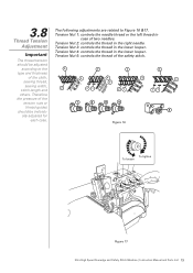
... loosen 3 2 1 Figure 17 Ultra High Speed Overedge and Safety Stitch Machine | Instruction Manual and Parts List 13 Tension Nut 5: controls the thread of two needles. Important Tension Nut 4: controls the thread in Thread Tension Adjustment case of the safety stitch. ally adjusted for each case. 3.8 The following adjustments are related to the 3 3 3 3 type...
... loosen 3 2 1 Figure 17 Ultra High Speed Overedge and Safety Stitch Machine | Instruction Manual and Parts List 13 Tension Nut 5: controls the thread of two needles. Important Tension Nut 4: controls the thread in Thread Tension Adjustment case of the safety stitch. ally adjusted for each case. 3.8 The following adjustments are related to the 3 3 3 3 type...

Instruction Manual
Page 19
3.12 Parts Relation and Timing 3,4 Thread 5 Thread (a) Top surface of the (a) needle plate Figure 21 (g) (f) Figure 24 (c) (e) (b) (d) Figure 22 Figure 23 Top surface of the needle plate (h) Figure 25 Top surface of ...
3.12 Parts Relation and Timing 3,4 Thread 5 Thread (a) Top surface of the (a) needle plate Figure 21 (g) (f) Figure 24 (c) (e) (b) (d) Figure 22 Figure 23 Top surface of the needle plate (h) Figure 25 Top surface of ...

Instruction Manual
Page 21
... with looper. 5. Replace the part. 1. Install needle correctly. Inadequate tension of needle. 2. Thread is thicker than needle hole. 2. Damaged needle. 4. Pass thread correctly. 3. Wrong installation of thread. 3. Fill in the silicon oil. 5. Set the thread stand correctly. 7. Pass thread correctly. 2. Adjust the thread tension units. 4. Adjust the needle and looper. Wrong passage of needle guards. 7. Replace...
... with looper. 5. Replace the part. 1. Install needle correctly. Inadequate tension of needle. 2. Thread is thicker than needle hole. 2. Damaged needle. 4. Pass thread correctly. 3. Wrong installation of thread. 3. Fill in the silicon oil. 5. Set the thread stand correctly. 7. Pass thread correctly. 2. Adjust the thread tension units. 4. Adjust the needle and looper. Wrong passage of needle guards. 7. Replace...

Instruction Manual
Page 22
... replace knives. 5. Adjust presser foot correctly. 2. Polish thread tension disc. Needle plate or presser foot with looper. 7. Threading correctly. 2. Pass thread correctly. 5. Adjust relation of needle with burrs. 6. Replace the part. 8. Thread tension is too thick. 1. Inadequate pressure on presser foot...Needle is too strong. 2. Replace the needle. 7. Adjust the height of feed dog. 8. Use proper needle to cloth and thread. 1. Knives does not cut perfectly. 5. Knives does not cut perfectly. 5. Adjust lower knife correctly. 4. Adjust the height of...
... replace knives. 5. Adjust presser foot correctly. 2. Polish thread tension disc. Needle plate or presser foot with looper. 7. Threading correctly. 2. Pass thread correctly. 5. Adjust relation of needle with burrs. 6. Replace the part. 8. Thread tension is too thick. 1. Inadequate pressure on presser foot...Needle is too strong. 2. Replace the needle. 7. Adjust the height of feed dog. 8. Use proper needle to cloth and thread. 1. Knives does not cut perfectly. 5. Knives does not cut perfectly. 5. Adjust lower knife correctly. 4. Adjust the height of...

Instruction Manual
Page 25
Part No. 1 P03010 2 P03017 3 20711001 4 20713027 5 P03018 6 20628023 7 20701002 8 207S13003 9 206S30001 10 P03019 11 20126001 12 20726009 Description Pin Pin Indicator guide Pipe Pin Plug Bracket Assembly Screw Bed pin Pin Pin Pin (for 321D-251H only) 3 thread 1 1 2 2 1 1 1 2 4 1 1 0 Qty 4 thread 1 1 2 2 1 1 1 2 4 1 1 0 5 thread 1 1 2 2 1 0 1 2 4 1 1 1 Ultra High Speed Overedge and Safety Stitch Machine | Instruction Manual and Parts List 23 6.1 Machine Bed Frame Components No.
Part No. 1 P03010 2 P03017 3 20711001 4 20713027 5 P03018 6 20628023 7 20701002 8 207S13003 9 206S30001 10 P03019 11 20126001 12 20726009 Description Pin Pin Indicator guide Pipe Pin Plug Bracket Assembly Screw Bed pin Pin Pin Pin (for 321D-251H only) 3 thread 1 1 2 2 1 1 1 2 4 1 1 0 Qty 4 thread 1 1 2 2 1 1 1 2 4 1 1 0 5 thread 1 1 2 2 1 0 1 2 4 1 1 1 Ultra High Speed Overedge and Safety Stitch Machine | Instruction Manual and Parts List 23 6.1 Machine Bed Frame Components No.

Instruction Manual
Page 27
... Screw Pin Screw Spring Latch Screw Screw Screw Latch Screw Flat spring Screw Front cover (left) Screw Side cover Threading diagram Threading diagram Singer S cameo Model plate Singer resin plate Revit 3 thread 1 4 1 3 1 1 1 2 2 1 0 4 1 3 1 1 1 1 3 1 2 1 1 1 1 1 1 1 1 1 1 2 1 1 0 1 2 1 6 Qty 4 thread 1 4 1 3 1 1 1 2 2 1 0 4 1 3 1 1 1 1 3 1 2 1 1 1 1 1 1 1 1 1 1 2 1 1 0 1 2 1 6 5 thread 1 4 1 3 1 1 1 2 2 1 1 4 1 3 1 1 1 1 3 1 2 1 1 1 1 1 1 1 1 1 0 2 1 1 1 1 2 1 6 Ultra High Speed Overedge and Safety Stitch Machine | Instruction Manual and Parts List 25 6.2 Machine Cover Components(1) No...
... Screw Pin Screw Spring Latch Screw Screw Screw Latch Screw Flat spring Screw Front cover (left) Screw Side cover Threading diagram Threading diagram Singer S cameo Model plate Singer resin plate Revit 3 thread 1 4 1 3 1 1 1 2 2 1 0 4 1 3 1 1 1 1 3 1 2 1 1 1 1 1 1 1 1 1 1 2 1 1 0 1 2 1 6 Qty 4 thread 1 4 1 3 1 1 1 2 2 1 0 4 1 3 1 1 1 1 3 1 2 1 1 1 1 1 1 1 1 1 1 2 1 1 0 1 2 1 6 5 thread 1 4 1 3 1 1 1 2 2 1 1 4 1 3 1 1 1 1 3 1 2 1 1 1 1 1 1 1 1 1 0 2 1 1 1 1 2 1 6 Ultra High Speed Overedge and Safety Stitch Machine | Instruction Manual and Parts List 25 6.2 Machine Cover Components(1) No...

Instruction Manual
Page 29
... guide Screw Eye guide Eye guide Screw Washer Bracket Screw Washer Bed cover plate assembly Screw Gasket Cover plate Screw Screw Nut Oil Reservoir Cushion 3 thread 0 1 1 1 1 1 1 1 0 1 1 1 2 2 1 1 1 1 2 1 1 1 1 1 2 1 0 2 2 1 1 2 1 5 1 1 4 1 1 1 Qty 4 thread 0 1 1 1 1 1 1 1 0 1 1 1 2 2 1 1 1 1 2 1 1 1 1 1 2 1 0 2 2 1 1 2 1 5 1 1 4 1 1 1 5 thread 1 0 1 1 1 1 1 1 1 0 1 1 2 2 1 1 1 1 2 1 1 1 1 1 2 0 1 2 2 1 1 2 1 5 1 1 4 1 1 1 Ultra High Speed Overedge and Safety Stitch Machine | Instruction Manual and Parts List 27...
... guide Screw Eye guide Eye guide Screw Washer Bracket Screw Washer Bed cover plate assembly Screw Gasket Cover plate Screw Screw Nut Oil Reservoir Cushion 3 thread 0 1 1 1 1 1 1 1 0 1 1 1 2 2 1 1 1 1 2 1 1 1 1 1 2 1 0 2 2 1 1 2 1 5 1 1 4 1 1 1 Qty 4 thread 0 1 1 1 1 1 1 1 0 1 1 1 2 2 1 1 1 1 2 1 1 1 1 1 2 1 0 2 2 1 1 2 1 5 1 1 4 1 1 1 5 thread 1 0 1 1 1 1 1 1 1 0 1 1 2 2 1 1 1 1 2 1 1 1 1 1 2 0 1 2 2 1 1 2 1 5 1 1 4 1 1 1 Ultra High Speed Overedge and Safety Stitch Machine | Instruction Manual and Parts List 27...

Instruction Manual
Page 31
... bearing Ball bearing Washer Oil seal O ring O ring Right cover Screw Fan assembly Machine pulley Screw Screw Spring washer Pin Cover Screw Screw Spacer Cover 3 thread 1 0 4 2 4 1 1 1 3 1 1 1 1 1 1 1 4 1 1 1 1 3 1 1 2 1 1 0 0 0 0 1 1 Qty 4 thread 1 0 4 2 4 1 1 1 3 1 1 1 1 1 1 1 4 1 1 1 1 3 1 1 2 1 1 0 0 0 0 1 1 5 thread 1 1 4 2 4 1 0 0 0 1 1 1 1 1 1 1 4 1 1 1 1 3 1 1 2 1 1 1 1 2 1 1 1 Ultra High Speed Overedge and Safety Stitch Machine | Instruction Manual and Parts List 29 6.4 Crank Shaft Drive Components No...
... bearing Ball bearing Washer Oil seal O ring O ring Right cover Screw Fan assembly Machine pulley Screw Screw Spring washer Pin Cover Screw Screw Spacer Cover 3 thread 1 0 4 2 4 1 1 1 3 1 1 1 1 1 1 1 4 1 1 1 1 3 1 1 2 1 1 0 0 0 0 1 1 Qty 4 thread 1 0 4 2 4 1 1 1 3 1 1 1 1 1 1 1 4 1 1 1 1 3 1 1 2 1 1 0 0 0 0 1 1 5 thread 1 1 4 2 4 1 0 0 0 1 1 1 1 1 1 1 4 1 1 1 1 3 1 1 2 1 1 1 1 2 1 1 1 Ultra High Speed Overedge and Safety Stitch Machine | Instruction Manual and Parts List 29 6.4 Crank Shaft Drive Components No...

Instruction Manual
Page 32
6.5 Thread Tension Components 7 6 5 1 4 8 3 7 18 6 5 16 4 8 3 19 7 6 5 9 4 10 3 7 20 6 5 17 4 10 3 21 For 1-needle 14 12 11 17 13 9 15 1 For 2-needle 14 17 12 11 13 9 16 1 Ultra High Speed Overedge and Safety Stitch Machine | Instruction Manual and Parts List 30
6.5 Thread Tension Components 7 6 5 1 4 8 3 7 18 6 5 16 4 8 3 19 7 6 5 9 4 10 3 7 20 6 5 17 4 10 3 21 For 1-needle 14 12 11 17 13 9 15 1 For 2-needle 14 17 12 11 13 9 16 1 Ultra High Speed Overedge and Safety Stitch Machine | Instruction Manual and Parts List 30

Instruction Manual
Page 33
6.5 Thread Tension Components No. Part No. 1 2071100400 3 30111006 4 301110052 5 30128016 6 20623008 7 201S30016 8 20727011 9 2071100500 10 30127013 11 20713001 12 207S11007 13 20712015 14 20612052 15 207S110014 ... 2071100700 18 301S160062R 19 301S160062Y 20 301S160062B 21 301S160062G Description Tension spring assembly Rachet Cup Tension disc Felt Screw stud Spring Tension spring assembly Spring Thread guide Screw Thread guide Tension guide Screw Tension spring assembly Tension spring assembly Knob (red dot) Knob (Yellow dot) Knob (blue dot) Knob (Green dot...
6.5 Thread Tension Components No. Part No. 1 2071100400 3 30111006 4 301110052 5 30128016 6 20623008 7 201S30016 8 20727011 9 2071100500 10 30127013 11 20713001 12 207S11007 13 20712015 14 20612052 15 207S110014 ... 2071100700 18 301S160062R 19 301S160062Y 20 301S160062B 21 301S160062G Description Tension spring assembly Rachet Cup Tension disc Felt Screw stud Spring Tension spring assembly Spring Thread guide Screw Thread guide Tension guide Screw Tension spring assembly Tension spring assembly Knob (red dot) Knob (Yellow dot) Knob (blue dot) Knob (Green dot...

Instruction Manual
Page 34
6.6 Thread Guide and Thread Take-up Components (1) 1 9 2 For 5-thread 8 16 13 10 14 12 15 17 18 19 20 6 5 7 3 22 21 4 11 Ultra High Speed Overedge and Safety Stitch Machine | Instruction Manual and Parts List 32
6.6 Thread Guide and Thread Take-up Components (1) 1 9 2 For 5-thread 8 16 13 10 14 12 15 17 18 19 20 6 5 7 3 22 21 4 11 Ultra High Speed Overedge and Safety Stitch Machine | Instruction Manual and Parts List 32


