
Instruction Manual
Page 2
... and V-Belt Specifications 5 3 Mounting and Adjustment Instructions 6 3.1 Table Cut-Out Diagram 6 3.2 Machine Installation 7 3.3 Lubrication and Oil Drainage 9 3.4 Fill Silicon Oil to Reservoir 10 3.5 Needle Attachment (or Replacement) 10 3.6 Replacing Upper and Lower Knife 11 3.7 Machine Threading 12 3.8 Thread Tension Adjustment 13 3.9 Presser foot pressure 14 3.10 Adjusting the Differential...
... and V-Belt Specifications 5 3 Mounting and Adjustment Instructions 6 3.1 Table Cut-Out Diagram 6 3.2 Machine Installation 7 3.3 Lubrication and Oil Drainage 9 3.4 Fill Silicon Oil to Reservoir 10 3.5 Needle Attachment (or Replacement) 10 3.6 Replacing Upper and Lower Knife 11 3.7 Machine Threading 12 3.8 Thread Tension Adjustment 13 3.9 Presser foot pressure 14 3.10 Adjusting the Differential...

Instruction Manual
Page 3
... Take-up Components (1) 32 6.7 Thread Guide and Thread Take-up Components (2) 34 6.8 Thread Guide and Thread Take-up Components (3) 36 6.9 Needle Bar Components (1) 38 6.10 Needle Bar Components (2) 40 6.11 Needle Plate and Needle Guard Components 42 6.12 Upper Looper Components 44 6.13 Lower Looper Components 46 6.14 Chain Stitch Looper Components (1) 48 6.15...
... Take-up Components (1) 32 6.7 Thread Guide and Thread Take-up Components (2) 34 6.8 Thread Guide and Thread Take-up Components (3) 36 6.9 Needle Bar Components (1) 38 6.10 Needle Bar Components (2) 40 6.11 Needle Plate and Needle Guard Components 42 6.12 Upper Looper Components 44 6.13 Lower Looper Components 46 6.14 Chain Stitch Looper Components (1) 48 6.15...

Instruction Manual
Page 4
...safety devices. • The machine should be immediately stopped. • Before starting the machine in full running, a test must be followed. Singer will not be held responsible for any electric device is damaged, the machine should only be operated by properly trained personnel. • For ...that all basic safety instructions are not limited to the following situations arise: • Passing the thread by the needle or replacing the bobbin or looper. • Replacing the needle, presser foot, throat plate, feed dog and sliding plate. • When the machine is in maintenance. &#...
...safety devices. • The machine should be immediately stopped. • Before starting the machine in full running, a test must be followed. Singer will not be held responsible for any electric device is damaged, the machine should only be operated by properly trained personnel. • For ...that all basic safety instructions are not limited to the following situations arise: • Passing the thread by the needle or replacing the bobbin or looper. • Replacing the needle, presser foot, throat plate, feed dog and sliding plate. • When the machine is in maintenance. &#...
Instruction Manual
Page 7
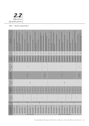
Machine Specification Ultra High Speed Overedge and Safety Stitch Machine | Instruction Manual and Parts List 4 Singer Model Needle Gauge [mm] Overedge Bight [mm] Stitch Length [mm] Differential Rate Presser Foot Lift [mm] Singer Needle Cat Speed [spm] Application 321D-131M-04 4 321D-131M-04 / KS 4 13 - 321D-132M-015 1.5 321D-134M-04 4 ...6500 Five-thread heavy duty overlock machine 7 6120-06 130/21 6500 Five-thread heavy duty overlock machine with horizontal chain cutter and AFL device Needles Threads With Clutch Motor 2.2 Machine Specification Table 1 -
Machine Specification Ultra High Speed Overedge and Safety Stitch Machine | Instruction Manual and Parts List 4 Singer Model Needle Gauge [mm] Overedge Bight [mm] Stitch Length [mm] Differential Rate Presser Foot Lift [mm] Singer Needle Cat Speed [spm] Application 321D-131M-04 4 321D-131M-04 / KS 4 13 - 321D-132M-015 1.5 321D-134M-04 4 ...6500 Five-thread heavy duty overlock machine 7 6120-06 130/21 6500 Five-thread heavy duty overlock machine with horizontal chain cutter and AFL device Needles Threads With Clutch Motor 2.2 Machine Specification Table 1 -

Instruction Manual
Page 10
In case of semi-submerged assembly, the distance between the needle plate top surface and the table top is around 100 mm. For fullysubmerged assembly, the distance is around 5.0 mm. 3 2 1 9 10 12 4 5 7 6 8 11 Figure 2 Ultra High Speed Overedge and Safety Stitch Machine | Instruction Manual and Parts List 7 3.2 Machine Installation Install the machine support components and the cloth waste chute as indicated in Figure 2.
In case of semi-submerged assembly, the distance between the needle plate top surface and the table top is around 100 mm. For fullysubmerged assembly, the distance is around 5.0 mm. 3 2 1 9 10 12 4 5 7 6 8 11 Figure 2 Ultra High Speed Overedge and Safety Stitch Machine | Instruction Manual and Parts List 7 3.2 Machine Installation Install the machine support components and the cloth waste chute as indicated in Figure 2.

Instruction Manual
Page 12
... the machine before running it. Then remove three screws and remove oil filter cap. Remove the rubber plug and fill the lubricant oil (Singer Oil) until the indicator of the oil level between 'L' and 'H' lines of the motor rotation. After draining the oil, replace the screw and fi...on Figure 7. After that must be cleaned every month or changed every six months. After that has not been used for some time, oil the needle bar top, the guides and looper before oiling and assuming the direction of the oil level sight window. To replace the oil filter, ...
... the machine before running it. Then remove three screws and remove oil filter cap. Remove the rubber plug and fill the lubricant oil (Singer Oil) until the indicator of the oil level between 'L' and 'H' lines of the motor rotation. After draining the oil, replace the screw and fi...on Figure 7. After that must be cleaned every month or changed every six months. After that has not been used for some time, oil the needle bar top, the guides and looper before oiling and assuming the direction of the oil level sight window. To replace the oil filter, ...

Instruction Manual
Page 13
... it up until the bar end.. Figure 9 (a) OK! Insert the needle to prevent needle thread breakage and fabric damage. Tighten screw '1'. Insert the needle with the Allen key wrench in order to the proper depth. Figure 8 3.5 Needle Attachment (or Replacement) Use only Singer's Cat. 6120 needles Loosen screw '1' as indicated on Figure 8. 3.4 Fill Silicon Oil to...
... it up until the bar end.. Figure 9 (a) OK! Insert the needle to prevent needle thread breakage and fabric damage. Tighten screw '1'. Insert the needle with the Allen key wrench in order to the proper depth. Figure 8 3.5 Needle Attachment (or Replacement) Use only Singer's Cat. 6120 needles Loosen screw '1' as indicated on Figure 8. 3.4 Fill Silicon Oil to...

Instruction Manual
Page 14
... '3' and then upper knife '4'. To install a new upper knife, turn the handwheel until the upper knife holder reaches the lowest position of the needle plate 6 Figure 12 (a) Adjusting overedge width I. Make sure the upper and lower knives mate positively. Install a new knife by 0.5~1.0 mm according ... upper knife 1. Overlap the cutting edges of the upper and lower knives so that midpoint 'A' on upper knife '4' and the midpoint of the needle plate 6 Figure 12 (b) Ultra High Speed Overedge and Safety Stitch Machine | Instruction Manual and Parts List 11 A 4 Top surface of lower ...
... '3' and then upper knife '4'. To install a new upper knife, turn the handwheel until the upper knife holder reaches the lowest position of the needle plate 6 Figure 12 (a) Adjusting overedge width I. Make sure the upper and lower knives mate positively. Install a new knife by 0.5~1.0 mm according ... upper knife 1. Overlap the cutting edges of the upper and lower knives so that midpoint 'A' on upper knife '4' and the midpoint of the needle plate 6 Figure 12 (b) Ultra High Speed Overedge and Safety Stitch Machine | Instruction Manual and Parts List 11 A 4 Top surface of lower ...
Instruction Manual
Page 15
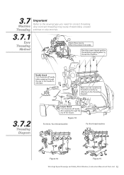
Knot the preset thread and the thread being used together to thread the machine. 2 Needle thread Trim the knots off neatly after passing through the eye of the looper. Figure 13 For three / four thread machine For five thread ... covers. 3.7 Machine Threading Important Refer to the threading diagram. 3.7.2 Threading Diagram 4 Looper thread Trim the knots off neatly before passing through the yey of the needle to rethread. 3 Make sure the machine is threaded correctly by referring to the sewing type you need for correct threading. Move the presser foot aside.
Knot the preset thread and the thread being used together to thread the machine. 2 Needle thread Trim the knots off neatly after passing through the eye of the looper. Figure 13 For three / four thread machine For five thread ... covers. 3.7 Machine Threading Important Refer to the threading diagram. 3.7.2 Threading Diagram 4 Looper thread Trim the knots off neatly before passing through the yey of the needle to rethread. 3 Make sure the machine is threaded correctly by referring to the sewing type you need for correct threading. Move the presser foot aside.
Instruction Manual
Page 16
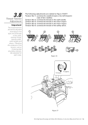
... the cloth, sewing thread, 4 4 4 4 5 sewing width, 2 stitch length and 21 21 21 others. Tension Nut 3: controls the thread in the right needle. Tension Nut 5: controls the thread of two needles. The thread tension should be adjusted according to Figure 16 &17. Important Tension Nut 4: controls the thread in Thread Tension Adjustment case...
... the cloth, sewing thread, 4 4 4 4 5 sewing width, 2 stitch length and 21 21 21 others. Tension Nut 3: controls the thread in the right needle. Tension Nut 5: controls the thread of two needles. The thread tension should be adjusted according to Figure 16 &17. Important Tension Nut 4: controls the thread in Thread Tension Adjustment case...

Instruction Manual
Page 19
... Figure 21 (g) (f) Figure 24 (c) (e) (b) (d) Figure 22 Figure 23 Top surface of the needle plate (h) Figure 25 Top surface of the needle plate Figure 26 Figure 27 Model 321D & 321K Upper looper Feed dog Height of needle (Figure 21) Lower looper left limit position (Figure 22) Upper looper left limit position ( c ) (Figure 23) Height...
... Figure 21 (g) (f) Figure 24 (c) (e) (b) (d) Figure 22 Figure 23 Top surface of the needle plate (h) Figure 25 Top surface of the needle plate Figure 26 Figure 27 Model 321D & 321K Upper looper Feed dog Height of needle (Figure 21) Lower looper left limit position (Figure 22) Upper looper left limit position ( c ) (Figure 23) Height...

Instruction Manual
Page 20
... be sure the V-belt is not excessively worn out and see topic 3.3) If the machine was idle for a long time, oil the top of the needle holder, guides and looper guides before resuming the operation. Do not use any kind of dust on the machine head. Figure 28 4.2 Oil Change and...
... be sure the V-belt is not excessively worn out and see topic 3.3) If the machine was idle for a long time, oil the top of the needle holder, guides and looper guides before resuming the operation. Do not use any kind of dust on the machine head. Figure 28 4.2 Oil Change and...

Instruction Manual
Page 21
.... 5. Adjust the thread tension unit. Adjust the relation of needle with looper. 2. Skip stitches 4. Damaged needle. 4. Thread is thicker than the eye of needle with looper. 5. Pass thread correctly. 4. Wrong relation of the needle. 2. Use adequate needle to cloth and thread. 3. Use proper needle hole for a new needle. 7. Failure in stitches 3. Broken thread 5. Replace the parts. 9. Replace...
.... 5. Adjust the thread tension unit. Adjust the relation of needle with looper. 2. Skip stitches 4. Damaged needle. 4. Thread is thicker than the eye of needle with looper. 5. Pass thread correctly. 4. Wrong relation of the needle. 2. Use adequate needle to cloth and thread. 3. Use proper needle hole for a new needle. 7. Failure in stitches 3. Broken thread 5. Replace the parts. 9. Replace...

Instruction Manual
Page 22
...5. Thread tension is not correct. 6. Differential feed is too strong. 2. Incorrect presser foot. 2. Wrong passage of lower knfe. 4. Needle plate or presser foot with burrs. 6. Threading correctly. 2. Replace the part. 6. Adjust the height of thread stand. 3. Adjust thread ...tension. 2. Adjust or replace knives. 5. Use proper needle to cloth and thread. 1. Pass thread correctly. 5. Replace the part. 8. Wrong installation of feed dog. 8. Needle is too thick. 1. Thread tension inadequate. 6. Possible Solutions 1. Adjust or replace knives...
...5. Thread tension is not correct. 6. Differential feed is too strong. 2. Incorrect presser foot. 2. Wrong passage of lower knfe. 4. Needle plate or presser foot with burrs. 6. Threading correctly. 2. Replace the part. 6. Adjust the height of thread stand. 3. Adjust thread ...tension. 2. Adjust or replace knives. 5. Use proper needle to cloth and thread. 1. Pass thread correctly. 5. Replace the part. 8. Wrong installation of feed dog. 8. Needle is too thick. 1. Thread tension inadequate. 6. Possible Solutions 1. Adjust or replace knives...

Instruction Manual
Page 32
6.5 Thread Tension Components 7 6 5 1 4 8 3 7 18 6 5 16 4 8 3 19 7 6 5 9 4 10 3 7 20 6 5 17 4 10 3 21 For 1-needle 14 12 11 17 13 9 15 1 For 2-needle 14 17 12 11 13 9 16 1 Ultra High Speed Overedge and Safety Stitch Machine | Instruction Manual and Parts List 30
6.5 Thread Tension Components 7 6 5 1 4 8 3 7 18 6 5 16 4 8 3 19 7 6 5 9 4 10 3 7 20 6 5 17 4 10 3 21 For 1-needle 14 12 11 17 13 9 15 1 For 2-needle 14 17 12 11 13 9 16 1 Ultra High Speed Overedge and Safety Stitch Machine | Instruction Manual and Parts List 30

Instruction Manual
Page 40
6.9 Needle Bar Components (1) 6 5 25 13 12 19 17 18 7 16 14 15 21 20 22 23 24 9 8 11 10 3 4 1 2 Ultra High Speed Overedge and Safety Stitch Machine | Instruction Manual and Parts List 38
6.9 Needle Bar Components (1) 6 5 25 13 12 19 17 18 7 16 14 15 21 20 22 23 24 9 8 11 10 3 4 1 2 Ultra High Speed Overedge and Safety Stitch Machine | Instruction Manual and Parts List 38

Instruction Manual
Page 41
6.9 Needle Bar Components (1) No. Part No. 1 20705001 2 207811016 3 20626003 4 207814007 5 20704001 6 S05018 7 20702002 8 20708004 9 207814001 10 20628014... 25 20722004 Description Connection assembly Screw Pin Screw Crank assembly Screw Shaft Collar Screw Washer Ring Lever assembly Screw Shaft assembly Shaft Oil wick Needle bar bushing assembly Needle Bar Bushing Screw O ring Oil felt Ring assembly Screw Plug 3 thread 1 2 1 1 1 1 1 1 2 1 1 1 1 1 1 1 1 1 1 1 1 1 1 1 1 Qty 4 thread 1 2 1 1 1 1 1 1 2 1 1 1 1 1 1 1 1 1 1 1 1 1 1 1 1 5 thread 1 2 1 1 1 1 1 1 2 1 1 1 1 1 1 1 1 1 1 1 1 1 1 1 1 ...
6.9 Needle Bar Components (1) No. Part No. 1 20705001 2 207811016 3 20626003 4 207814007 5 20704001 6 S05018 7 20702002 8 20708004 9 207814001 10 20628014... 25 20722004 Description Connection assembly Screw Pin Screw Crank assembly Screw Shaft Collar Screw Washer Ring Lever assembly Screw Shaft assembly Shaft Oil wick Needle bar bushing assembly Needle Bar Bushing Screw O ring Oil felt Ring assembly Screw Plug 3 thread 1 2 1 1 1 1 1 1 2 1 1 1 1 1 1 1 1 1 1 1 1 1 1 1 1 Qty 4 thread 1 2 1 1 1 1 1 1 2 1 1 1 1 1 1 1 1 1 1 1 1 1 1 1 1 5 thread 1 2 1 1 1 1 1 1 2 1 1 1 1 1 1 1 1 1 1 1 1 1 1 1 1 ...

Instruction Manual
Page 42
6.10 Needle Bar Components (2) For 3 thread 11 12 15 14 13 For 4 thread 9 10 7 8 6 For 5 thread 1 2 5 4 3 Ultra High Speed Overedge and Safety Stitch Machine | Instruction Manual and Parts List 40
6.10 Needle Bar Components (2) For 3 thread 11 12 15 14 13 For 4 thread 9 10 7 8 6 For 5 thread 1 2 5 4 3 Ultra High Speed Overedge and Safety Stitch Machine | Instruction Manual and Parts List 40

Instruction Manual
Page 43
... 10 207S11024 11 XXXXXXXX 12 207S14009 13 20713038 14 207S11024 15 XXXXXXXX Description 3 thread Needle holder assembly 0 Screw 0 Thread guide (except 321D-251H / 321K-251H) 0 Screw 0 Needle 0 Needle 0 Needle holder assembly 0 Screw 0 Thread guide 0 Screw 0 Needle holder assembly 1 Screw 1 Thread guide 1 Screw 1 Needle 1 Qty 4 thread 0 0 0 0 0 2 1 2 1 1 0 0 0 0 0 5 thread 1 2 1 1 2 0 0 0 0 0 0 0 0 0 0 Ultra High Speed Overedge and Safety Stitch Machine | Instruction Manual...
... 10 207S11024 11 XXXXXXXX 12 207S14009 13 20713038 14 207S11024 15 XXXXXXXX Description 3 thread Needle holder assembly 0 Screw 0 Thread guide (except 321D-251H / 321K-251H) 0 Screw 0 Needle 0 Needle 0 Needle holder assembly 0 Screw 0 Thread guide 0 Screw 0 Needle holder assembly 1 Screw 1 Thread guide 1 Screw 1 Needle 1 Qty 4 thread 0 0 0 0 0 2 1 2 1 1 0 0 0 0 0 5 thread 1 2 1 1 2 0 0 0 0 0 0 0 0 0 0 Ultra High Speed Overedge and Safety Stitch Machine | Instruction Manual...

Instruction Manual
Page 44
6.11 Needle Plate and Needle Guard Components For 5-thread 2 1 7 6 4 3 5 15 14 9 8 17 16 19 18 11 13 12 10 For 3-thread / 4-thread 21 20 26 25 23 22 24 28 27 30 32 31 29 Ultra High Speed Overedge and Safety Stitch Machine | Instruction Manual and Parts List 42
6.11 Needle Plate and Needle Guard Components For 5-thread 2 1 7 6 4 3 5 15 14 9 8 17 16 19 18 11 13 12 10 For 3-thread / 4-thread 21 20 26 25 23 22 24 28 27 30 32 31 29 Ultra High Speed Overedge and Safety Stitch Machine | Instruction Manual and Parts List 42


