Instruction Manual
Page 5
... safety instructions which are adequate to specifications and technical rules in your safety, goggles must be run with attention all instruction before using this manual, and use should be followed. • Singer will not be held responsible for any damage caused by properly trained personnel. • For your country. • The machine should...
... safety instructions which are adequate to specifications and technical rules in your safety, goggles must be run with attention all instruction before using this manual, and use should be followed. • Singer will not be held responsible for any damage caused by properly trained personnel. • For your country. • The machine should...
Instruction Manual
Page 11
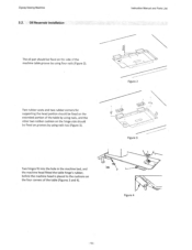
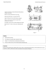
... corners for supporting the head portion should be fixed on the extended portion of the table by using nails, and the other two rubber cushion on the hinge side should be fixed on the four corners of... the machine table groove by using four nails (Figure 2). Two hinges fit into the hole in the machine bed, and the ... the table hinge's rubber, before the machine head is placed to the cushions on grooves by using nails too (Figure 3). Oil Reservoir Installation The oil pan should be fixed on the side of the table...
... corners for supporting the head portion should be fixed on the extended portion of the table by using nails, and the other two rubber cushion on the hinge side should be fixed on the four corners of... the machine table groove by using four nails (Figure 2). Two hinges fit into the hole in the machine bed, and the ... the table hinge's rubber, before the machine head is placed to the cushions on grooves by using nails too (Figure 3). Oil Reservoir Installation The oil pan should be fixed on the side of the table...
Instruction Manual
Page 12
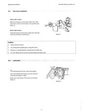
... Figure 6). 1 0 Figure 6 Lubrication '406' Rotating hook and area under throat plate. Wit Figure 5 Caution: • Switch off the machine. • Set sewing head upright again using both hands. • Danger of oil to the oil hole (see Figure 5).
... Figure 6). 1 0 Figure 6 Lubrication '406' Rotating hook and area under throat plate. Wit Figure 5 Caution: • Switch off the machine. • Set sewing head upright again using both hands. • Danger of oil to the oil hole (see Figure 5).
Instruction Manual
Page 13
... of bread-in Figure? Clean and oil the places indicated with letter 'B'. Remove screws and lift off the machine. • Set sewing head upright again using both hands. • Danger of oil to all other oiling points shown Keep oil pad 'A' under arm top cover saturated with oil.
... of bread-in Figure? Clean and oil the places indicated with letter 'B'. Remove screws and lift off the machine. • Set sewing head upright again using both hands. • Danger of oil to all other oiling points shown Keep oil pad 'A' under arm top cover saturated with oil.

Instruction Manual
Page 14
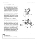
... Caution: • The power supply should be used . No. 1910-05 needle system (135x9) only. Make sure its highest position by turning hand wheel toward the front. Tighten -,,edle set screw '1' (see Figure 8). Raise needle bar to the table below Model Application Light weight materials 20U-109 / 109C / 112 / 112C / 309 Medium weight...
... Caution: • The power supply should be used . No. 1910-05 needle system (135x9) only. Make sure its highest position by turning hand wheel toward the front. Tighten -,,edle set screw '1' (see Figure 8). Raise needle bar to the table below Model Application Light weight materials 20U-109 / 109C / 112 / 112C / 309 Medium weight...
Instruction Manual
Page 21
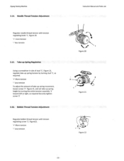
... Regulate bobbin thread tension with tension regulating knob '1', Figure 20. • more tension '-' less tension 3.15. Figure 21 Figure 22 -20- Take-up Spring Regulation Using a screwdriver in slot of take -up spring movement, loosen screw '2'. Zigzag Sewing Machine 3.14. Needle Thread Tension Adjustment Instruction Manual and Parts List Regulate needle...
... Regulate bobbin thread tension with tension regulating knob '1', Figure 20. • more tension '-' less tension 3.15. Figure 21 Figure 22 -20- Take-up Spring Regulation Using a screwdriver in slot of take -up spring movement, loosen screw '2'. Zigzag Sewing Machine 3.14. Needle Thread Tension Adjustment Instruction Manual and Parts List Regulate needle...
Instruction Manual
Page 25
...X4I, oc.•o u.i12.112C: 2 I 2C) Figure 27 .00 1 45.064.1.3 4.06493 Figure 28 Open bed slide, then remove throat plate, (Use screwdriver '3' Figure 29, furnished with machine for removal and replacement of feed dog slots in place. To replace general purpose or straight stitch feed dog...;101PC•109. 6,064, 12.4,•• 3 404464 ,70,1-•011V•01.C.-.10., 606502 ,2•24J• •1 I O... Replace bed plate and press it will not hit the edges of throat plate and feed dog.) Using a screwdriver '2' remove bed plate '1' and remove feed dog '4' (see ...
...X4I, oc.•o u.i12.112C: 2 I 2C) Figure 27 .00 1 45.064.1.3 4.06493 Figure 28 Open bed slide, then remove throat plate, (Use screwdriver '3' Figure 29, furnished with machine for removal and replacement of feed dog slots in place. To replace general purpose or straight stitch feed dog...;101PC•109. 6,064, 12.4,•• 3 404464 ,70,1-•011V•01.C.-.10., 606502 ,2•24J• •1 I O... Replace bed plate and press it will not hit the edges of throat plate and feed dog.) Using a screwdriver '2' remove bed plate '1' and remove feed dog '4' (see ...

Instruction Manual
Page 26
Set height of spool rest so there is approximately 2.0 mm clearance between top end of spool pin and the tip of the slotted spigot of the spool cap (see Figure 31) The spool cap should never be fitted on the spool pin '5'. Forcing it onto the spool pin may result in breaking the slotted spigot of the spool cap (see Figure 31). Sig 5 Figure 31 - 25 - Zigzag Sewing Machine 3.22_ Spool Cap Usage Instruction Manual and Parts List When using a reel type thread spool, fit the spool cap '1' supplied with the machine onto the thread spool '3' (see Figure 31).
Set height of spool rest so there is approximately 2.0 mm clearance between top end of spool pin and the tip of the slotted spigot of the spool cap (see Figure 31) The spool cap should never be fitted on the spool pin '5'. Forcing it onto the spool pin may result in breaking the slotted spigot of the spool cap (see Figure 31). Sig 5 Figure 31 - 25 - Zigzag Sewing Machine 3.22_ Spool Cap Usage Instruction Manual and Parts List When using a reel type thread spool, fit the spool cap '1' supplied with the machine onto the thread spool '3' (see Figure 31).

Instruction Manual
Page 27
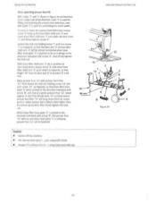
Knee Lifter Installation Knee lifter mounting Fasten knee lifter bracket '1' to hang free at the top of table '2' 145mm from table cut-out as shown in Figure 33 Instruction Manual and Parts List 2 Figure 32 145 mm ti 1 2 Figure 33 -26- Zigzag Sewing Machine 3.23. Anti-Spill Sleeve Usage When using synthetic threads that easily spill off the cone '1', slip the anti-pill sleeve '2' furnished with the machine over the thread from the bottom of cone '1' leaving the thread end to underside of antispill sleeve '2' as shown in Figure 32 3.24.
Knee Lifter Installation Knee lifter mounting Fasten knee lifter bracket '1' to hang free at the top of table '2' 145mm from table cut-out as shown in Figure 33 Instruction Manual and Parts List 2 Figure 32 145 mm ti 1 2 Figure 33 -26- Zigzag Sewing Machine 3.23. Anti-Spill Sleeve Usage When using synthetic threads that easily spill off the cone '1', slip the anti-pill sleeve '2' furnished with the machine over the thread from the bottom of cone '1' leaving the thread end to underside of antispill sleeve '2' as shown in Figure 32 3.24.
Instruction Manual
Page 28
To raise or lower the presser foot with knee, and bell crank '2' is used for lifting and lowering the presser loot with knee, loosen screw '4' holding screw '7' and turn screw '14' as required, so that knee lifter knee plate '5' ..., so that the bent end '6' of knee lifter shaft arm '3' will be lowered. A 5 Caution: • Switch off the machine. • Set sewing head uprignv zgain using both hands_ • Danger of the bed bell crank '1' is...
To raise or lower the presser foot with knee, and bell crank '2' is used for lifting and lowering the presser loot with knee, loosen screw '4' holding screw '7' and turn screw '14' as required, so that knee lifter knee plate '5' ..., so that the bent end '6' of knee lifter shaft arm '3' will be lowered. A 5 Caution: • Switch off the machine. • Set sewing head uprignv zgain using both hands_ • Danger of the bed bell crank '1' is...
Instruction Manual
Page 29
... Loosen the lock nut holding screw '7' and turn screw '14' as required, so that height '10' from zero to maximum stitch width. (20U-109 / 109C / 308: 9mm or 20U-112 / 112C: 12mm). Instruction Manual and Parts List 12 11 13 2 14 3 67 10 67 rnm Figure 35 Caution: • Switch off... arrow 'B', will stop at the maximum stitch width position of knee lifter shaft arm '3' will be moved from its bent end '6' to bracket is used for lifting and lowering the presser foot with knee, loosen screw '4' holding screw '14' and turn screw '7' as required, so that stitch width ...
... Loosen the lock nut holding screw '7' and turn screw '14' as required, so that height '10' from zero to maximum stitch width. (20U-109 / 109C / 308: 9mm or 20U-112 / 112C: 12mm). Instruction Manual and Parts List 12 11 13 2 14 3 67 10 67 rnm Figure 35 Caution: • Switch off... arrow 'B', will stop at the maximum stitch width position of knee lifter shaft arm '3' will be moved from its bent end '6' to bracket is used for lifting and lowering the presser foot with knee, loosen screw '4' holding screw '14' and turn screw '7' as required, so that stitch width ...
Instruction Manual
Page 30
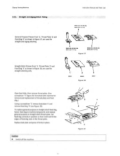
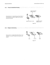
Fittings for Hem Sewing Hemmer Foot '1', Straight Stitch Throat Plate '2' and Feed Dog '3' as shown in Figure37 are used for buttonhole stitching. 1 6066.2 ,20U-109.109C:11,112C•110. 3 606600 426U-1425,105C:509. 606502 (30U-112.11a, Figure 36 3.26. I 410192 2 Sat 91£-452 Figure 37 543.70 Fittings for Buttonhole Stitching .06652 e201J-109:105.C.305) 606.02 1201L 112:112C, 2 Buttonhole Foot '1', General Purpose Throat Plate '2' and Feed Dog '3' as shown in Figure 36 are used for hem sewing. Zigzag Sewing Machine Instruction Manual and Parts List 3.25.
Fittings for Hem Sewing Hemmer Foot '1', Straight Stitch Throat Plate '2' and Feed Dog '3' as shown in Figure37 are used for buttonhole stitching. 1 6066.2 ,20U-109.109C:11,112C•110. 3 606600 426U-1425,105C:509. 606502 (30U-112.11a, Figure 36 3.26. I 410192 2 Sat 91£-452 Figure 37 543.70 Fittings for Buttonhole Stitching .06652 e201J-109:105.C.305) 606.02 1201L 112:112C, 2 Buttonhole Foot '1', General Purpose Throat Plate '2' and Feed Dog '3' as shown in Figure 36 are used for hem sewing. Zigzag Sewing Machine Instruction Manual and Parts List 3.25.

Instruction Manual
Page 31
Figure 38 Fittings for Zipper and Cord Sewing Instruction Manual and Parts List Zipper Foot '1', General Purpose '2' or Straight Stitch '3' Throat Plate and General Purpose '4' or Straight Stitch '5' Feed Dog as shown in Figure 38 are used for zipper and cord sewing. 2 i2OLI•100.100.,206. 606402 .2OU .112,112.) 4 606640 ,2012-100,100C•900) 606502 (2OU-112.•112C1 606606 0 60446) Caution: • Switch off the machine. Zigzag Sewing Machine 3.27.
Figure 38 Fittings for Zipper and Cord Sewing Instruction Manual and Parts List Zipper Foot '1', General Purpose '2' or Straight Stitch '3' Throat Plate and General Purpose '4' or Straight Stitch '5' Feed Dog as shown in Figure 38 are used for zipper and cord sewing. 2 i2OLI•100.100.,206. 606402 .2OU .112,112.) 4 606640 ,2012-100,100C•900) 606502 (2OU-112.•112C1 606606 0 60446) Caution: • Switch off the machine. Zigzag Sewing Machine 3.27.

Instruction Manual
Page 32
Do not use any kind of lacquer thinner to remove the excess of dust on the machine head. Safety Inspection Check periodically if all fixing and supporting screws ...
Do not use any kind of lacquer thinner to remove the excess of dust on the machine head. Safety Inspection Check periodically if all fixing and supporting screws ...


