
Instruction Manual
Page 2
... Cover and Bobbin Winder Installation 7 3.4 Lubrication 8 3.5 ThreadTake-up Lever Oil Supply Adjustment 8 3.6 Rotating Hook Oil Supply Adjustment 9 3.7 Needle Attachment 10 3.8 Bobbin Case Attachment 11 3.9 MachineThreading 11 3.10 Stitch Length Adjustment 12 3.11 ThreadTension Adjustment 12 3.12 ThreadTake-Up Spring Adjustment...14 3.15 Presser Foot Pressure Adjustment 15 3.16 FeedTiming Adjustment 16 3.17 Feed Dog Height Adjustment 17 3.18 Needle to Rotating Hook Relation Adjustment 18 3.19 Presser Bar Height Adjustment 19 3.20 ThreadTake-Up Stroke Adjustment 20 ...
... Cover and Bobbin Winder Installation 7 3.4 Lubrication 8 3.5 ThreadTake-up Lever Oil Supply Adjustment 8 3.6 Rotating Hook Oil Supply Adjustment 9 3.7 Needle Attachment 10 3.8 Bobbin Case Attachment 11 3.9 MachineThreading 11 3.10 Stitch Length Adjustment 12 3.11 ThreadTension Adjustment 12 3.12 ThreadTake-Up Spring Adjustment...14 3.15 Presser Foot Pressure Adjustment 15 3.16 FeedTiming Adjustment 16 3.17 Feed Dog Height Adjustment 17 3.18 Needle to Rotating Hook Relation Adjustment 18 3.19 Presser Bar Height Adjustment 19 3.20 ThreadTake-Up Stroke Adjustment 20 ...

Instruction Manual
Page 3
Contents 6 Parts List 23 6.1 Frame and Cover Components 24 6.2 Arm Shaft andThreadTake-Up Lever Components 26 6.3 Needle Bar, Upright Shaft and Rotating Hook Driving Shaft 28 Components 6.4 Presser Foot Components 30 6.5 Feed Mechanism Components 32 6.6 Lubrication Components 34 6.7 Oil Reservoir Components 36 6.8 Belt Cover, Bobbin Winder andThread Stand Components 38 6.9 Machine Accessories 40
Contents 6 Parts List 23 6.1 Frame and Cover Components 24 6.2 Arm Shaft andThreadTake-Up Lever Components 26 6.3 Needle Bar, Upright Shaft and Rotating Hook Driving Shaft 28 Components 6.4 Presser Foot Components 30 6.5 Feed Mechanism Components 32 6.6 Lubrication Components 34 6.7 Oil Reservoir Components 36 6.8 Belt Cover, Bobbin Winder andThread Stand Components 38 6.9 Machine Accessories 40

Instruction Manual
Page 4
...the product. High Speed Straight Lockstitch Sewing Machine | Instruction Manual and Parts List 1 If any damage caused by qualified personnel. Singer will not be followed. Safety Instructions 1.1 Important Safety Instructions Important When using the machine, basic safety procedures must be conducted ...basic safety instructions are not limited to the following situations arise: • Passing the thread by the needle or replacing the bobbin or looper. • Replacing the needle, presser foot, throat plate, feed dog and sliding plate. • When the machine is in maintenance...
...the product. High Speed Straight Lockstitch Sewing Machine | Instruction Manual and Parts List 1 If any damage caused by qualified personnel. Singer will not be followed. Safety Instructions 1.1 Important Safety Instructions Important When using the machine, basic safety procedures must be conducted ...basic safety instructions are not limited to the following situations arise: • Passing the thread by the needle or replacing the bobbin or looper. • Replacing the needle, presser foot, throat plate, feed dog and sliding plate. • When the machine is in maintenance...

Instruction Manual
Page 7
... Stroke [mm] Hook Type Hook Origin Needle Cat. Lubrication Lubrication Oil 191D-20 Light to medium 191D-20C Standard 5,000 5.0 5.5/13.0 30.7 1955-01 #14 Koban/ Hirose Regular 191D-30 Medium to heavy 4,500 5.0 5.5/13.0 35.0 191D-30C Standard Koban/ Hirose 1955-01 #18 Fully Automatic Lubrication Singer "C" type oil 191D-70 Heavy 191D-70C Standard 3,000 7.0 5.5/13.0 35.0 Large...
... Stroke [mm] Hook Type Hook Origin Needle Cat. Lubrication Lubrication Oil 191D-20 Light to medium 191D-20C Standard 5,000 5.0 5.5/13.0 30.7 1955-01 #14 Koban/ Hirose Regular 191D-30 Medium to heavy 4,500 5.0 5.5/13.0 35.0 191D-30C Standard Koban/ Hirose 1955-01 #18 Fully Automatic Lubrication Singer "C" type oil 191D-70 Heavy 191D-70C Standard 3,000 7.0 5.5/13.0 35.0 Large...

Instruction Manual
Page 11
...purpose of bread-in direction 'C'. 3.4 Lubrication Precaution When you will see splashing oil through oil sight window '2' if the lubrication is brought close to needle bar crank '2' by turning the adjusting pin '1' in direction 'B'. Before turning the machine on, fill oil reservoir '1' with the specified oil. When...machine after set up Lever Oil Supply Adjustment Adjust the amount of the splashing oil is brought to the position just opposite from the needle bar crank by turning the adjusting pin '1' in . The minimum amount of the lubricating oil. The maximum amount of oil is ...
...purpose of bread-in direction 'C'. 3.4 Lubrication Precaution When you will see splashing oil through oil sight window '2' if the lubrication is brought close to needle bar crank '2' by turning the adjusting pin '1' in direction 'B'. Before turning the machine on, fill oil reservoir '1' with the specified oil. When...machine after set up Lever Oil Supply Adjustment Adjust the amount of the splashing oil is brought to the position just opposite from the needle bar crank by turning the adjusting pin '1' in . The minimum amount of the lubricating oil. The maximum amount of oil is ...
Instruction Manual
Page 13
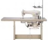
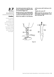
...of its indented part 'A' facing exactly to the right in the direction of sewing material used. Tighten the screw '2'. 3.7 Needle Attachment Caution Choose a proper needle size according to the left in direction 'D'. Figure 12 High Speed Straight Lockstitch Sewing Machine | Instruction Manual and Parts List ...10 Loosen screw '2' and hold needle '1' with its stroke (Figure 12). Make sure the long groove 'C' of the needle is facing exactly to the count of thread and the type of the arrow until it will...
...of its indented part 'A' facing exactly to the right in the direction of sewing material used. Tighten the screw '2'. 3.7 Needle Attachment Caution Choose a proper needle size according to the left in direction 'D'. Figure 12 High Speed Straight Lockstitch Sewing Machine | Instruction Manual and Parts List ...10 Loosen screw '2' and hold needle '1' with its stroke (Figure 12). Make sure the long groove 'C' of the needle is facing exactly to the count of thread and the type of the arrow until it will...
Instruction Manual
Page 14
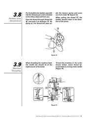
Figure 13 3.9 Machine Threading When threading the machine head, the needle bar should rotate in the needle (Figure 14). Figure 14 High Speed Straight Lockstitch Sewing Machine | Instruction Manual and Parts List 11 Thread the machine in direction 'C'. der the tension spring ...
Figure 13 3.9 Machine Threading When threading the machine head, the needle bar should rotate in the needle (Figure 14). Figure 14 High Speed Straight Lockstitch Sewing Machine | Instruction Manual and Parts List 11 Thread the machine in direction 'C'. der the tension spring ...
Instruction Manual
Page 15
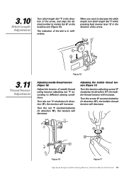
... Figure 17 High Speed Straight Lockstitch Sewing Machine | Instruction Manual and Parts List 12 Figure 15 3.11 Thread Tension Adjustment Adjusting needle thread tension (Figure 16) Adjust the tension of needle thread using tension adjusting nut '1' according to decrease the stitch length, turn stitch length dial '1' while pressing feed reverse lever '2' in...
... Figure 17 High Speed Straight Lockstitch Sewing Machine | Instruction Manual and Parts List 12 Figure 15 3.11 Thread Tension Adjustment Adjusting needle thread tension (Figure 16) Adjust the tension of needle thread using tension adjusting nut '1' according to decrease the stitch length, turn stitch length dial '1' while pressing feed reverse lever '2' in...

Instruction Manual
Page 17
... of presser foot is turned down in direction 'B' (Figure 23). 3.13 Knee Lifter Height Adjustment When using the knee lifter, the standard height of the needle bar '2' in its original position when the lifter is 10 mm.
... of presser foot is turned down in direction 'B' (Figure 23). 3.13 Knee Lifter Height Adjustment When using the knee lifter, the standard height of the needle bar '2' in its original position when the lifter is 10 mm.

Instruction Manual
Page 19
... cam '1' in the direction of the arrow. For the standard adjustment, adjust so that the top surface of feed dog and the top end of needle eyelet are flush with top surface of the arrow, and firmly tighten the screws '2' and '3' (Figure 25). To advance the feed timing in order to... Straight Lockstitch Sewing Machine | Instruction Manual and Parts List 16 3.16 Feed Timing Adjustment Caution If the feed eccentric cam is moved too far, the needle will be broken.
... cam '1' in the direction of the arrow. For the standard adjustment, adjust so that the top surface of feed dog and the top end of needle eyelet are flush with top surface of the arrow, and firmly tighten the screws '2' and '3' (Figure 25). To advance the feed timing in order to... Straight Lockstitch Sewing Machine | Instruction Manual and Parts List 16 3.16 Feed Timing Adjustment Caution If the feed eccentric cam is moved too far, the needle will be broken.

Instruction Manual
Page 21
... (Figure 27) Turn the handwheel until the line 'B' on the needle bar '2' align with the bottom end of needle bar lower bushing '3'. Adjusting the height of needle '4', and make sure the clearance between the needle and the rotating hook '5' is too small, the rotating hook points ... List 18 After the above adjustments steps, the rotating hook point '5' aligns with the bottom end of needle bar lower bushing '3', then securely tighten the setscrew '1'. 3.18 Needle to Rotating Hook Relation Adjustment Precaution If the clearance is 0.04~0.1 mm. When replacing the rotating hook,...
... (Figure 27) Turn the handwheel until the line 'B' on the needle bar '2' align with the bottom end of needle bar lower bushing '3'. Adjusting the height of needle '4', and make sure the clearance between the needle and the rotating hook '5' is too small, the rotating hook points ... List 18 After the above adjustments steps, the rotating hook point '5' aligns with the bottom end of needle bar lower bushing '3', then securely tighten the setscrew '1'. 3.18 Needle to Rotating Hook Relation Adjustment Precaution If the clearance is 0.04~0.1 mm. When replacing the rotating hook,...

Instruction Manual
Page 25
... off, polish or replace by a new part 6. Replace needle 1. Readjust needle and hook point 1. Readjust the presser foot pressure 4. Needle doesn't center the needle hole of needle and hook point 2. Thread tension disc, thread guide, needle, hook point and needle plate are burred 8. Wrong relation with rotary hook 5. Needle is bended 4. Inadequate thread tension 4. Inadequate pressure of feed...
... off, polish or replace by a new part 6. Replace needle 1. Readjust needle and hook point 1. Readjust the presser foot pressure 4. Needle doesn't center the needle hole of needle and hook point 2. Thread tension disc, thread guide, needle, hook point and needle plate are burred 8. Wrong relation with rotary hook 5. Needle is bended 4. Inadequate thread tension 4. Inadequate pressure of feed...
Instruction Manual
Page 30
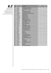
... Screw SM15/64 x 28 L=10.5 Screw Thread take-up lever link Thread take-up lever link Thread take-up lever link assembly Needle bearing Needle bar crank Needle bar crank Needle bar crank Needle bar crank rod Screw SM9/64 x 40 L=4.8 Screw SM9/32 x 28 L=16 Counter weight Screw SM1/4 x40 L=6 Rubber ring... bushing (middle) Screw Thrust collar Hand wheel Screw SM15/64 x 28 L=15 Arm shaft Roller felt Oil amount adjusting pin Qty. 20 20C 30 30C 70 70C 111111 111111 111111 110000 001100 000011 222222 110000 001100 000011 111111 111111 111111 111111 222222 111111 111111 111100 000011 222222 111111 222222...
... Screw SM15/64 x 28 L=10.5 Screw Thread take-up lever link Thread take-up lever link Thread take-up lever link assembly Needle bearing Needle bar crank Needle bar crank Needle bar crank Needle bar crank rod Screw SM9/64 x 40 L=4.8 Screw SM9/32 x 28 L=16 Counter weight Screw SM1/4 x40 L=6 Rubber ring... bushing (middle) Screw Thrust collar Hand wheel Screw SM15/64 x 28 L=15 Arm shaft Roller felt Oil amount adjusting pin Qty. 20 20C 30 30C 70 70C 111111 111111 111111 110000 001100 000011 222222 110000 001100 000011 111111 111111 111111 111111 222222 111111 111111 111100 000011 222222 111111 222222...

Instruction Manual
Page 31
... 10102021 4 10138002 5 101S11005 6 10109001 7 10113001 10113009 8 10103010 10103023 Description Cap Needle bar bushing (upper) Needle bar Needle bar Needle bar Needle bar connection Screw SM9/64 x 40 L=6 Slide block Needle bar thread guide Needle bar thread guide Needle bar bushing (lower) Needle bar bushing (lower) Qty. 20 20C 30 30C 70 70C 111111 111111 110000 001100 000011 111111 111111 111111...
... 10102021 4 10138002 5 101S11005 6 10109001 7 10113001 10113009 8 10103010 10103023 Description Cap Needle bar bushing (upper) Needle bar Needle bar Needle bar Needle bar connection Screw SM9/64 x 40 L=6 Slide block Needle bar thread guide Needle bar thread guide Needle bar bushing (lower) Needle bar bushing (lower) Qty. 20 20C 30 30C 70 70C 111111 111111 110000 001100 000011 111111 111111 111111...

Instruction Manual
Page 32
... 26 10112016 10112032 27 101S11011 28 1010000000 29 101S15008 30 10122015 31 10123002 32 10102006 12202003 33 10118501 10118517 10818502 34 10123003 35 101S30005 36 101S15006 37 10109002 38 101S11008 Description Screw SM 1/8 x 44 L=4.5 Needle bar thread guide Needle #14 Needle #18 Needle #21 Gear Screw SMI/4 x 40 L=8 Pinion ...shaft Bobbin case Bobbin case Bobbin case Oil wick Oil seal screw Screw SM3/16 x 28 L=12 Needle bar slid block guide Screw SM11/64x40 L=8 Qty. 20 20C 30 30C 70 70C 111111 111111 110000 001100 000011 111111 888888 111111 111111 111111 111111 111100 000011 111111 111111 ...
... 26 10112016 10112032 27 101S11011 28 1010000000 29 101S15008 30 10122015 31 10123002 32 10102006 12202003 33 10118501 10118517 10818502 34 10123003 35 101S30005 36 101S15006 37 10109002 38 101S11008 Description Screw SM 1/8 x 44 L=4.5 Needle bar thread guide Needle #14 Needle #18 Needle #21 Gear Screw SMI/4 x 40 L=8 Pinion ...shaft Bobbin case Bobbin case Bobbin case Oil wick Oil seal screw Screw SM3/16 x 28 L=12 Needle bar slid block guide Screw SM11/64x40 L=8 Qty. 20 20C 30 30C 70 70C 111111 111111 110000 001100 000011 111111 888888 111111 111111 111111 111111 111100 000011 111111 111111 ...

Instruction Manual
Page 44
... 7 10131004 8 10118003 10818501 9 IP07042-001 10 10111011 11 1011105500 12 10131001 Description Machine hinge plate Machine hinge rubber cushion Nail Set Needle #14 Needle #18 Needle #21 Screw driver (large) Screw driver (medium) Screw driver (small) Bobbin Bobbin Dust cover Machine rest pin Oil container Oil reservoir... magnet Qty. 20 20C 30 30C 70 70C 222222 222222 444444 330000 003300 000033 111111 111111 111111 333300 000033 111111 ...
... 7 10131004 8 10118003 10818501 9 IP07042-001 10 10111011 11 1011105500 12 10131001 Description Machine hinge plate Machine hinge rubber cushion Nail Set Needle #14 Needle #18 Needle #21 Screw driver (large) Screw driver (medium) Screw driver (small) Bobbin Bobbin Dust cover Machine rest pin Oil container Oil reservoir... magnet Qty. 20 20C 30 30C 70 70C 222222 222222 444444 330000 003300 000033 111111 111111 111111 333300 000033 111111 ...


