

XL-MP150 Operation Manual
Page 8
... page 1. AC Power Cord 12 3. Woofer 3. MP3 Indicator 17 5. FM 75 Ohms Antenna Terminal 11 4. Cooling Fan 12 8. Subwoofer Pre-output Jack 37 „ Speaker system 1. FM Stereo Mode Indicator 26 13. Speaker Terminals 11 2. MP3/WMA Title Indicators 22...Speaker Light-up Jacks 11 9. Speaker Wire 5. AC INPUT RIGHT LEFT SUBWOOFER PRE-OUT 3 4 5 6 7 8 9 „ Display Reference page 1. Daily Timer Indicator 33 12. Video/Auxiliary (Audio Signal) Input Jacks 36 7. XL-MP150 Controls and indicators (continued) 12 3 45 6 78 9 General Information...
... page 1. AC Power Cord 12 3. Woofer 3. MP3 Indicator 17 5. FM 75 Ohms Antenna Terminal 11 4. Cooling Fan 12 8. Subwoofer Pre-output Jack 37 „ Speaker system 1. FM Stereo Mode Indicator 26 13. Speaker Terminals 11 2. MP3/WMA Title Indicators 22...Speaker Light-up Jacks 11 9. Speaker Wire 5. AC INPUT RIGHT LEFT SUBWOOFER PRE-OUT 3 4 5 6 7 8 9 „ Display Reference page 1. Daily Timer Indicator 33 12. Video/Auxiliary (Audio Signal) Input Jacks 36 7. XL-MP150 Controls and indicators (continued) 12 3 45 6 78 9 General Information...

XL-MP150 Operation Manual
Page 11
...To turn off the speaker light-up wires to the SPEAKERS LIGHT-UP jacks for 2 seconds or more , as lower im- AC INPUT RIGHT LEFT SUBWOOFER PRE-OUT Note: Placing the right speaker light-up wire to the AM LOOP jack. Place the AM loop antenna on the right side when... wire to the RIGHT jack and the left channels. pedance speakers can be placed in the direction where the strongest signal can damage the unit. XL-MP150 Preparation for Use „ Antenna connection Supplied FM antenna: Connect the FM antenna wire to the plus (+) terminal. The right speaker is the one ...
...To turn off the speaker light-up wires to the SPEAKERS LIGHT-UP jacks for 2 seconds or more , as lower im- AC INPUT RIGHT LEFT SUBWOOFER PRE-OUT Note: Placing the right speaker light-up wire to the AM LOOP jack. Place the AM loop antenna on the right side when... wire to the RIGHT jack and the left channels. pedance speakers can be placed in the direction where the strongest signal can damage the unit. XL-MP150 Preparation for Use „ Antenna connection Supplied FM antenna: Connect the FM antenna wire to the plus (+) terminal. The right speaker is the one ...

XL-MP150 Operation Manual
Page 12
...VIDEO/AUX IN RIGHT LEFT SUBWOOFER PRE-OUT Note: When an outdoor FM antenna is in use for Use SPEAKERS SPEAKERS LIGHT-UP LEFT RIGHT „ AC power connection After checking all the connections have been made correctly, plug the AC power cord of time. XL-MP150 System connections (continued) ... (demonstration mode), press the X-BASS (SURROUND)/ DEMO button. If you plug in , the unit will enter the demonstration mode. AC INPUT RIGHT LEFT SUBWOOFER PRE-OUT AC outlet (AC 120 V, 60 Hz) Notes: z The unit will enter the low power consumption mode. To cancel the demonstration mode:...
...VIDEO/AUX IN RIGHT LEFT SUBWOOFER PRE-OUT Note: When an outdoor FM antenna is in use for Use SPEAKERS SPEAKERS LIGHT-UP LEFT RIGHT „ AC power connection After checking all the connections have been made correctly, plug the AC power cord of time. XL-MP150 System connections (continued) ... (demonstration mode), press the X-BASS (SURROUND)/ DEMO button. If you plug in , the unit will enter the demonstration mode. AC INPUT RIGHT LEFT SUBWOOFER PRE-OUT AC outlet (AC 120 V, 60 Hz) Notes: z The unit will enter the low power consumption mode. To cancel the demonstration mode:...

XL-MP150 Operation Manual
Page 36
ance is not included. cally. AC INPUT RIGHT LEFT SUBWOOFER PRE-OUT X-BASS (SURROUND) /DEMO „ Listening to connect the VCR, DVD, etc. z Be sure your system The connection cord is 32 ohms. z Plugging in ... plugging in the cassette compartment. 2 Press the VIDEO/AUX button. 3 Press the button. 4 Press the / ( ) or ( ) button. 5 Play the VCR, DVD, etc. Advanced Features SPEAKERS XL-MP150 Enhancing your headphones have a 1/8" (3.5 mm) diameter plug and impedance between 16 and 50 ohms. The recommended imped- Note: To prevent noise interference, place the unit...
ance is not included. cally. AC INPUT RIGHT LEFT SUBWOOFER PRE-OUT X-BASS (SURROUND) /DEMO „ Listening to connect the VCR, DVD, etc. z Be sure your system The connection cord is 32 ohms. z Plugging in ... plugging in the cassette compartment. 2 Press the VIDEO/AUX button. 3 Press the button. 4 Press the / ( ) or ( ) button. 5 Play the VCR, DVD, etc. Advanced Features SPEAKERS XL-MP150 Enhancing your headphones have a 1/8" (3.5 mm) diameter plug and impedance between 16 and 50 ohms. The recommended imped- Note: To prevent noise interference, place the unit...
XL-MP150 Operation Manual
Page 37
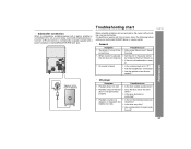
...the headphones connected? properly. z Is the disc very dirty? „ Subwoofer connection When a commercially available speaker with a built-in amplifier is connected to this product, check the following before calling your authorized SHARP dealer or service center. „ General Symptom Possible cause z The clock ...is not set to the SUBWOOFER PRE-OUT jack. ANTENNA AM FM 75 OHMS GND LOOP VIDEO/AUX IN RIGHT LEFT RATED SPEAKER IMPEDANCE: 6 OHMS MIN. the clock. XL-MP150 SPEAKERS ...
...the headphones connected? properly. z Is the disc very dirty? „ Subwoofer connection When a commercially available speaker with a built-in amplifier is connected to this product, check the following before calling your authorized SHARP dealer or service center. „ General Symptom Possible cause z The clock ...is not set to the SUBWOOFER PRE-OUT jack. ANTENNA AM FM 75 OHMS GND LOOP VIDEO/AUX IN RIGHT LEFT RATED SPEAKER IMPEDANCE: 6 OHMS MIN. the clock. XL-MP150 SPEAKERS ...
XL-MP150 Operation Manual
Page 41
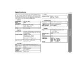
... specification figures indicated are nominal values of continuous improvement, SHARP reserves the right to 20 kHz, 10% total harmonic distortion Speakers: 6 ohms Headphones: 16 - 50 ohms (recommended: 32 ohms) Subwoofer pre-out (audio signal): 200 mV/10 k ohms at 70 Hz ...13 cm) woofer 220 W 110 W 6 ohms Width: 7-1/4" (185 mm) Height: 10-1/4" (260 mm) Depth: 10-1/4" (260 mm) 6.8 lbs. (3.1/ kg/each) References XL-MP150 41 Specifications As part of our policy of production units. There may be some deviations from these values in individual units. „ General Power source...
... specification figures indicated are nominal values of continuous improvement, SHARP reserves the right to 20 kHz, 10% total harmonic distortion Speakers: 6 ohms Headphones: 16 - 50 ohms (recommended: 32 ohms) Subwoofer pre-out (audio signal): 200 mV/10 k ohms at 70 Hz ...13 cm) woofer 220 W 110 W 6 ohms Width: 7-1/4" (185 mm) Height: 10-1/4" (260 mm) Depth: 10-1/4" (260 mm) 6.8 lbs. (3.1/ kg/each) References XL-MP150 41 Specifications As part of our policy of production units. There may be some deviations from these values in individual units. „ General Power source...

