
Service Manual
Page 1
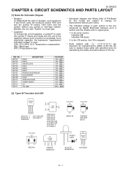
... original condition and only parts identical to change without notice. CIRCUIT SCHEMATICS AND PARTS LAYOUT [1] Notes On Schematic Diagram 6-1 [2] Types Of Transistor And LED 6-1 [3] Schematic Diagram 6-2 [4] Charts Of Connecting Wires 6-10 [5] Wiring Side of the set . " are subject to those specified be used . CONTENTS PRECAUTIONS FOR USING LEAD-FREE SOLDER CHAPTER 1. BLOCK DIAGRAM [1] Block Diagram 4-1 CHAPTER 5. FLOWCHART [1] Troubleshooting 7-1 CHAPTER 8. Be sure to be used for after sales service only. - 1 The contents...
... original condition and only parts identical to change without notice. CIRCUIT SCHEMATICS AND PARTS LAYOUT [1] Notes On Schematic Diagram 6-1 [2] Types Of Transistor And LED 6-1 [3] Schematic Diagram 6-2 [4] Charts Of Connecting Wires 6-10 [5] Wiring Side of the set . " are subject to those specified be used . CONTENTS PRECAUTIONS FOR USING LEAD-FREE SOLDER CHAPTER 1. BLOCK DIAGRAM [1] Block Diagram 4-1 CHAPTER 5. FLOWCHART [1] Troubleshooting 7-1 CHAPTER 8. Be sure to be used for after sales service only. - 1 The contents...
Service Manual
Page 2
... use , file it . Employing lead-free solder "MAIN, POWER, SPEAKER, TRANSIT iPOD, DISPLAY, HEADPHONE, RE-FLASH, VOLUME LED, iPOD, CD MP3 PWB" of lead-free solder. When the tip of it with the lead-free solder, apply lead-free wire solder. Example: Indicates lead-free solder of lead-free ...free wire solder or soldering bit, contact our service station or service branch in contact with polarity indication on the PWB and service manuals. Using lead-free wire solder When fixing the PWB soldered with steel wool or fine sandpaper. Lead-free wire solder for extended period of lead-free...
... use , file it . Employing lead-free solder "MAIN, POWER, SPEAKER, TRANSIT iPOD, DISPLAY, HEADPHONE, RE-FLASH, VOLUME LED, iPOD, CD MP3 PWB" of lead-free solder. When the tip of it with the lead-free solder, apply lead-free wire solder. Example: Indicates lead-free solder of lead-free ...free wire solder or soldering bit, contact our service station or service branch in contact with polarity indication on the PWB and service manuals. Using lead-free wire solder When fixing the PWB soldered with steel wool or fine sandpaper. Lead-free wire solder for extended period of lead-free...
Service Manual
Page 3
...) Amplifier Output power Output terminals Input terminals 20 watts minimum RMS per channel into 6 ohms from 100 Hz to do not perform any circuit should be attempted. 2. WARNING 1. CHAPTER 1. GENERAL DESCRIPTION XL-DK225 [1] Important Service Safety Precaution CAUTION : "These servicing instructions are qualified to 20 kHz, 10% total harmonic distortion Speakers: 6 ohms Headphones: 16 - 50 ohms (recommended: 32 ohms) Subwoofer pre-out (audio signal): 200 mV/10 k ohms at 70 Hz Video...
...) Amplifier Output power Output terminals Input terminals 20 watts minimum RMS per channel into 6 ohms from 100 Hz to do not perform any circuit should be attempted. 2. WARNING 1. CHAPTER 1. GENERAL DESCRIPTION XL-DK225 [1] Important Service Safety Precaution CAUTION : "These servicing instructions are qualified to 20 kHz, 10% total harmonic distortion Speakers: 6 ohms Headphones: 16 - 50 ohms (recommended: 32 ohms) Subwoofer pre-out (audio signal): 200 mV/10 k ohms at 70 Hz Video...
Service Manual
Page 4
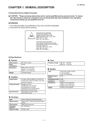
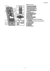
... Speaker Wire 2 4 1 - 24 Volume Control 13. MP3/WMA Folder Indicator 3. Daily Timer Indicator 10. Memory Indicator 13. Disc Pause Indicator 16. Disc Play Indicator Rear panel 3 1. Video Out Jack 8. Woofer 3. Disc Trays 3. Disc Stop Button 6. WMA Indicator 6. Disc Number Select Buttons 14. AM Antenna Ground Terminal 5. Bass Reflex Duct 1 3 4. Remote Sensor 5. Headphone Jack 12. Disc Tray Open/Close Button 12 3 45 67 13 14 15 16 9 10 11 8 12 Display 1. FM Stereo Receiving Indicator 12. AC Power Cord 3. Subwoofer Pre-output...
... Speaker Wire 2 4 1 - 24 Volume Control 13. MP3/WMA Folder Indicator 3. Daily Timer Indicator 10. Memory Indicator 13. Disc Pause Indicator 16. Disc Play Indicator Rear panel 3 1. Video Out Jack 8. Woofer 3. Disc Trays 3. Disc Stop Button 6. WMA Indicator 6. Disc Number Select Buttons 14. AM Antenna Ground Terminal 5. Bass Reflex Duct 1 3 4. Remote Sensor 5. Headphone Jack 12. Disc Tray Open/Close Button 12 3 45 67 13 14 15 16 9 10 11 8 12 Display 1. FM Stereo Receiving Indicator 12. AC Power Cord 3. Subwoofer Pre-output...
Service Manual
Page 5
...21. XL-DK225 Remote control 1 1. CD Track Up or Fast Forward, Tuner Preset Up, 3 Time Up Button 20 21 22 18. Volume Up and Down Buttons 9 2 7. Video/Auxiliary/iPod Button 11. Memory Button 14. Tuning Down Button 5 20. Tuner (Band) Button 10 10. Display Button 22. Clock/Timer Button 1 - 35 Disc Number Select Buttons 13 3. Disc Stop Button 13. Folder Button 23. Power On/Stand-by Button 8. Remote Control Transmitter 11 2. iPod Play or Pause Button 16. Disc Direct Search Buttons 7 4. Disc Clear/Dimmer Button 16 17 12. Extra Bass/Demo Button...
...21. XL-DK225 Remote control 1 1. CD Track Up or Fast Forward, Tuner Preset Up, 3 Time Up Button 20 21 22 18. Volume Up and Down Buttons 9 2 7. Video/Auxiliary/iPod Button 11. Memory Button 14. Tuning Down Button 5 20. Tuner (Band) Button 10 10. Display Button 22. Clock/Timer Button 1 - 35 Disc Number Select Buttons 13 3. Disc Stop Button 13. Folder Button 23. Power On/Stand-by Button 8. Remote Control Transmitter 11 2. iPod Play or Pause Button 16. Disc Direct Search Buttons 7 4. Disc Clear/Dimmer Button 16 17 12. Extra Bass/Demo Button...
Service Manual
Page 6
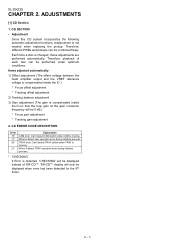
... adjustment functions, readjustment is moving . Items adjusted automatically 1) Offset adjustment (The offset voltage between the head amplifier output and the VREF reference voltage is compensated inside the IC so that the loop gain at the gain crossover frequency will be displayed when error had been detected for the 5th times. 2 - 1 Can't detect CAM switch when CAM is changed, these adjustments are performed automatically. Each time a disc...
... adjustment functions, readjustment is moving . Items adjusted automatically 1) Offset adjustment (The offset voltage between the head amplifier output and the VREF reference voltage is compensated inside the IC so that the loop gain at the gain crossover frequency will be displayed when error had been detected for the 5th times. 2 - 1 Can't detect CAM switch when CAM is changed, these adjustments are performed automatically. Each time a disc...
Service Manual
Page 7
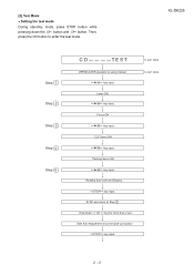
... Sub-code and Display key input. key input. Then, press the CD button to Step 1 Hold down the 3 button and 44 button. STOP and return to enter the test mode.\ XL-DK225 Step 1 Step 2 Step 3 Step 4 Step 5 CD TE ST OPEN/CLOSE operation is using manual. > key input. CLV Servo ON > key input. IL isn't done IL isn't done 2 - 2 Focus ON > key input. Laser ON. > key input. Start Auto Adjustment...
... Sub-code and Display key input. key input. Then, press the CD button to Step 1 Hold down the 3 button and 44 button. STOP and return to enter the test mode.\ XL-DK225 Step 1 Step 2 Step 3 Step 4 Step 5 CD TE ST OPEN/CLOSE operation is using manual. > key input. CLV Servo ON > key input. IL isn't done IL isn't done 2 - 2 Focus ON > key input. Laser ON. > key input. Start Auto Adjustment...
Service Manual
Page 8
XL-DK225 STOP and return to Step 1 Note Sliding the PICKUP with , > button can be set / >> for more than RW Judgement) = DA : XX - XXXX i) Focus Error (Other than 1 sec, it directly To cancel: Power OFF 2 - 3 XXXX key input. STOP and return to Step 1 Everytime > key input a) Focus Balance = FB : XX b) Focus Gain = FG : XX c) Tracking Balance = TB : XX d) Tracking Gain = TG : XX e) Focus Offset = FOFF : XX f) Tracking Offset = TOFF : XX g) RFRP = RFRP : XX h) Focus Error (RW Judgement) = RW : XX -
XL-DK225 STOP and return to Step 1 Note Sliding the PICKUP with , > button can be set / >> for more than RW Judgement) = DA : XX - XXXX i) Focus Error (Other than 1 sec, it directly To cancel: Power OFF 2 - 3 XXXX key input. STOP and return to Step 1 Everytime > key input a) Focus Balance = FB : XX b) Focus Gain = FG : XX c) Tracking Balance = TB : XX d) Tracking Gain = TG : XX e) Focus Offset = FOFF : XX f) Tracking Offset = TOFF : XX g) RFRP = RFRP : XX h) Focus Error (RW Judgement) = RW : XX -
Service Manual
Page 9
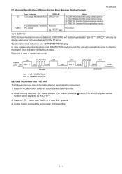
... NG during normal operation 21: TRAY SW Detection NG during initialize process PLL Unlock. (*) CHECKING: If CD changer mechanism error is ready for the 5th times. Speaker abnormal detection and +B PROTECTION display In case speaker abnormal detection or +B PROTECTION had been detected for transporting. [3] Standard Specification Of Stereo System Error Message Display Contents XL-DK225 CD TUNER Error Contents DISPLAY CD Changer Mechanism Error. 'ER-CD**' (*) Focus...
... NG during normal operation 21: TRAY SW Detection NG during initialize process PLL Unlock. (*) CHECKING: If CD changer mechanism error is ready for the 5th times. Speaker abnormal detection and +B PROTECTION display In case speaker abnormal detection or +B PROTECTION had been detected for transporting. [3] Standard Specification Of Stereo System Error Message Display Contents XL-DK225 CD TUNER Error Contents DISPLAY CD Changer Mechanism Error. 'ER-CD**' (*) Focus...
Service Manual
Page 10
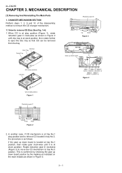
...postiiton. Figure 1 Reduction gear C Front Rear Figure 2 2. In another case, if CD mechanism is at tray No.1 play position and to eject the disc tray so that CD can be removed from the tray. CD Disc Mark 1 Mark 3 Mark 5 (DISC 1) (DISC 3) (DISC 5) Mark 2 Mark 4 (DISC 2) (DISC 4) Figure 4 CD at stock position, ...marking as indicated on the main chassis as shown in Figure 4. 3 - 1 Reduction gear D Up Down Figure 3 CD Disc Disc Tray Guide Tray Gear up down board CD at play position. MECHANICAL DESCRIPTION [1] Removing And Reinstalling The Main Parts 1. XL-DK255 CHAPTER 3.
...postiiton. Figure 1 Reduction gear C Front Rear Figure 2 2. In another case, if CD mechanism is at tray No.1 play position and to eject the disc tray so that CD can be removed from the tray. CD Disc Mark 1 Mark 3 Mark 5 (DISC 1) (DISC 3) (DISC 5) Mark 2 Mark 4 (DISC 2) (DISC 4) Figure 4 CD at stock position, ...marking as indicated on the main chassis as shown in Figure 4. 3 - 1 Reduction gear D Up Down Figure 3 CD Disc Disc Tray Guide Tray Gear up down board CD at play position. MECHANICAL DESCRIPTION [1] Removing And Reinstalling The Main Parts 1. XL-DK255 CHAPTER 3.
Service Manual
Page 11
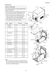
... or wire holders where they need to remove the power supply plug from electrostatic damage. XL-DK255 [2] Disassembly Caution on static electricity of integrated circuits and other circuits when servicing. (A1)x2 3x12mm (B1)x2 3x10mm Side Panel (Right) (A1)x2 3x12mm (B1)x2 3x10mm Rear Panel STEP REMOVAL 1 Top Cabinet 2 Side Panel (Left/Right) PROCEDURE 1. Screw K1) X 2 5 11 Jack PWB...
... or wire holders where they need to remove the power supply plug from electrostatic damage. XL-DK255 [2] Disassembly Caution on static electricity of integrated circuits and other circuits when servicing. (A1)x2 3x12mm (B1)x2 3x10mm Side Panel (Right) (A1)x2 3x12mm (B1)x2 3x10mm Rear Panel STEP REMOVAL 1 Top Cabinet 2 Side Panel (Left/Right) PROCEDURE 1. Screw K1) X 2 5 11 Jack PWB...
Service Manual
Page 12
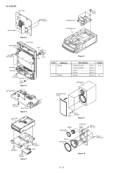
... 3 - 3 Catching Holder A2) X 4 3. XL-DK255 Rear Panel (H1)x2 Ø3x10mm CD Mechanism (P2)x4 Special Speaker PWB Figure 4 Display PWB Front Panel (J2)x1 CD Changer Unit (J4)x6 Ø2.6x10mm SUB PWB USB PWB (K1)x2 Ø2.6x10mm Jack PWB (L1)x1 Special Figure 5 Re-Flash PWB (J1)x1 (J3)x1 Figure 8 STEP REMOVAL 1 Woofer 2 Tweeter PROCEDURE 1. Screw A4...
... 3 - 3 Catching Holder A2) X 4 3. XL-DK255 Rear Panel (H1)x2 Ø3x10mm CD Mechanism (P2)x4 Special Speaker PWB Figure 4 Display PWB Front Panel (J2)x1 CD Changer Unit (J4)x6 Ø2.6x10mm SUB PWB USB PWB (K1)x2 Ø2.6x10mm Jack PWB (L1)x1 Special Figure 5 Re-Flash PWB (J1)x1 (J3)x1 Figure 8 STEP REMOVAL 1 Woofer 2 Tweeter PROCEDURE 1. Screw A4...
Service Manual
Page 23
... one with no signal given. 1. Be sure to replace these parts with " " ( ) are subject to electrolytic capacitor, the expression "capacitance/ withstand voltage" is used : this model are important for maintaining the safety and performance of the set . XL-DK225 CHAPTER 6. Besides, the one measured by Digital Multimeter between such a section and the chassis with "Fusible" is a fuse type. •...
... one with no signal given. 1. Be sure to replace these parts with " " ( ) are subject to electrolytic capacitor, the expression "capacitance/ withstand voltage" is used : this model are important for maintaining the safety and performance of the set . XL-DK225 CHAPTER 6. Besides, the one measured by Digital Multimeter between such a section and the chassis with "Fusible" is a fuse type. •...
Service Manual
Page 34
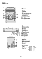
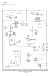
... 1 10 C N P 8 0 1 F 1 2 3 4 5 6 7 8 9 10 1 2 3 4 5 6 C N P 8 0 2 7654321 BI701 11 9 7 5 3 1 12 10 8 6 4 2 CNP705 2 4 6 8 10 13579 CNP702 17 15 13 16 14 C 1 2 CNS703 POWER PWB-A2 PT801 G WH BK H AC POWER SUPPLY CORD AC 120V~60Hz C N S 8 0 5 C N P 8 0 5 PT841 BI703 1 2 WH RD VOLUME LED PWB-B4 W H BI702 987654321 DISPLAY PWB-B1 1 2 C N P 7 0 3 R D W H B K W H B K W H B K RD WH BK WH BK WH BK WH CNS702 8 7 6 5 4 3 2 1 1 2 3 4 5 6 Figure 6-11: WIRING CONNECTION (1/2) 6 - 12
... 1 10 C N P 8 0 1 F 1 2 3 4 5 6 7 8 9 10 1 2 3 4 5 6 C N P 8 0 2 7654321 BI701 11 9 7 5 3 1 12 10 8 6 4 2 CNP705 2 4 6 8 10 13579 CNP702 17 15 13 16 14 C 1 2 CNS703 POWER PWB-A2 PT801 G WH BK H AC POWER SUPPLY CORD AC 120V~60Hz C N S 8 0 5 C N P 8 0 5 PT841 BI703 1 2 WH RD VOLUME LED PWB-B4 W H BI702 987654321 DISPLAY PWB-B1 1 2 C N P 7 0 3 R D W H B K W H B K W H B K RD WH BK WH BK WH BK WH CNS702 8 7 6 5 4 3 2 1 1 2 3 4 5 6 Figure 6-11: WIRING CONNECTION (1/2) 6 - 12
Service Manual
Page 54
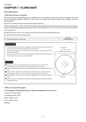
... pickup lens. CD optical pickup Lens cleaner disc Parts code UDSKA0004AFZZ HOW TO USE 1. You will hear music for 30-50 operations, however if the brushes become very wet then wipe off . In the event of this product is prohibited by build up of the optical pickup is clean. ...The CD cleaner disc must not be played 2.1. XL-DK225 CHAPTER 7. When a CD cannot be used on car CD players or on the CD cleaner disc which has the mark next to it still play button. 3. If not, clean it contact with a soft cloth. Turn the power off any adjustment make certain that ...
... pickup lens. CD optical pickup Lens cleaner disc Parts code UDSKA0004AFZZ HOW TO USE 1. You will hear music for 30-50 operations, however if the brushes become very wet then wipe off . In the event of this product is prohibited by build up of the optical pickup is clean. ...The CD cleaner disc must not be played 2.1. XL-DK225 CHAPTER 7. When a CD cannot be used on car CD players or on the CD cleaner disc which has the mark next to it still play button. 3. If not, clean it contact with a soft cloth. Turn the power off any adjustment make certain that ...

Service Manual
Page 55
...driver Q1 peripheral circuit. Press the Tray1 CD Eject Button without inserting a disc, and try starting the playback operation. 1 FDO IC1 22 2 TDO 23 IC1 XL-DK225 1. Is the RF waveform normal? (Waveform drawing Figure 3) No Sled motor (NM2). When a disc is displayed.... Although a CD is inserted and the cover is closed, "NO DISC" is loaded, start playback operation. 1. Does the pickup move up and down? (Waveform drawing Figure 1) Yes 3. No If the level...
...driver Q1 peripheral circuit. Press the Tray1 CD Eject Button without inserting a disc, and try starting the playback operation. 1 FDO IC1 22 2 TDO 23 IC1 XL-DK225 1. Is the RF waveform normal? (Waveform drawing Figure 3) No Sled motor (NM2). When a disc is displayed.... Although a CD is inserted and the cover is closed, "NO DISC" is loaded, start playback operation. 1. Does the pickup move up and down? (Waveform drawing Figure 1) Yes 3. No If the level...
Service Manual
Page 58
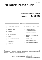
Be sure to be used for after sales service only. SHARP CORPORATION This document has been published to replace these parts with " ! " are subject to change without notice. The contents are important for maintaining the safety and performance of the set . XL-DK225 PARTS GUIDE MICRO COMPONENT SYSTEM MODEL XL-DK225 XL-DK225 Micro Component System consisting of the set . CONTENTS [1] INTEGRATED CIRCUITS [2] TRANSISTORS [3] DIODES [4] TRANSFORMERS [5] COILS [6] CRYSTALS...
Be sure to be used for after sales service only. SHARP CORPORATION This document has been published to replace these parts with " ! " are subject to change without notice. The contents are important for maintaining the safety and performance of the set . XL-DK225 PARTS GUIDE MICRO COMPONENT SYSTEM MODEL XL-DK225 XL-DK225 Micro Component System consisting of the set . CONTENTS [1] INTEGRATED CIRCUITS [2] TRANSISTORS [3] DIODES [4] TRANSFORMERS [5] COILS [6] CRYSTALS...
Service Manual
Page 67
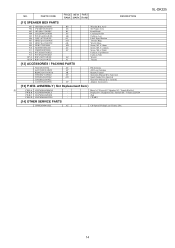
... Display Flat Wire, 5 Pin Socket, VIDEO / AUX IN RCA Jack Headphone Jack Socket, Sub Woofer Pre Out Lug Terminal Lug Terminal Lug Terminal Lug Terminal Lug Wire Relay,Power Relay Remote Sensor Speaker Jack Switch,Key Type [ DISC 4 ] Switch,Key Type [ DISC 5 ] Switch,Key Type [ OPEN/CLOSE ] Switch,Key Type [ DISC 1 ] Switch,Key Type [ DISC 2 ] Switch,Key Type [ DISC 3 ] Switch,Key Type [ POWER ON/STAND-BY ] Switch,Key Type [ PLAY/REPEAT ] Switch,Key Type [ STOP ] Switch,Key Type [ VIDEO/AUX ] Switch,Key Type [ TUNER / XM ] Switch...
... Display Flat Wire, 5 Pin Socket, VIDEO / AUX IN RCA Jack Headphone Jack Socket, Sub Woofer Pre Out Lug Terminal Lug Terminal Lug Terminal Lug Terminal Lug Wire Relay,Power Relay Remote Sensor Speaker Jack Switch,Key Type [ DISC 4 ] Switch,Key Type [ DISC 5 ] Switch,Key Type [ OPEN/CLOSE ] Switch,Key Type [ DISC 1 ] Switch,Key Type [ DISC 2 ] Switch,Key Type [ DISC 3 ] Switch,Key Type [ POWER ON/STAND-BY ] Switch,Key Type [ PLAY/REPEAT ] Switch,Key Type [ STOP ] Switch,Key Type [ VIDEO/AUX ] Switch,Key Type [ TUNER / XM ] Switch...
Service Manual
Page 70
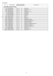
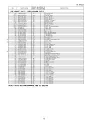
ARE 3XX XL-DK225 12 PARTS CODE PRICE NEW PART RANK MARK RANK DESCRIPTION [10] CABINET PARTS / CD MECHANISM PARTS 201 CCABA6896AW01 AX 201-1 - 201-2 ...Panel Ass'y Front Panel Panel, FL Display Badge, SHARP Button, Function, A Button, Disc No. Indicator, Volume Knob Decoration, Panel Fan Motor Ass'y Bracket, Fan Motor Rotary, Fan Motor, Air Cooling Fan (M971) Spring, Ring Spring, Ring Top Cabinet Disc Tray Cover Rear Panel [For America] Rear Panel [For Canada] Side Panel, Left Side Panel, Right Knob, VOLUME Nylon Band Bushing, AC Power Supply Cord Chassis, Main Holder, Fuse...
ARE 3XX XL-DK225 12 PARTS CODE PRICE NEW PART RANK MARK RANK DESCRIPTION [10] CABINET PARTS / CD MECHANISM PARTS 201 CCABA6896AW01 AX 201-1 - 201-2 ...Panel Ass'y Front Panel Panel, FL Display Badge, SHARP Button, Function, A Button, Disc No. Indicator, Volume Knob Decoration, Panel Fan Motor Ass'y Bracket, Fan Motor Rotary, Fan Motor, Air Cooling Fan (M971) Spring, Ring Spring, Ring Top Cabinet Disc Tray Cover Rear Panel [For America] Rear Panel [For Canada] Side Panel, Left Side Panel, Right Knob, VOLUME Nylon Band Bushing, AC Power Supply Cord Chassis, Main Holder, Fuse...
Service Manual
Page 72
PWB-C 92LPWB6894PODS - Main A1 / Power A2 / Speaker A3 / Transit iPod A4 Display B1 / Headphone B2 / Reflash B3 / Volume LED B4 iPod CD MP3 [14] OTHER SERVICE PARTS UDSKA0004AFZZ AZ CD Optical Pickup Lens Cleaner Disc XL-DK225 14 NO. ASSEMBLY ( Not Replacement Item ) ! PWB-B 92LPWB6894DPLS - PWB-D 92LPWB6894CDUS - PWB-A 92LPWB6895MANS - PARTS CODE PRICE NEW PART RANK MARK RANK DESCRIPTION [11] SPEAKER BOX PARTS 901 GBOXSA166AW01 BP 902 CWAKPA010AW05 AS 903...
PWB-C 92LPWB6894PODS - Main A1 / Power A2 / Speaker A3 / Transit iPod A4 Display B1 / Headphone B2 / Reflash B3 / Volume LED B4 iPod CD MP3 [14] OTHER SERVICE PARTS UDSKA0004AFZZ AZ CD Optical Pickup Lens Cleaner Disc XL-DK225 14 NO. ASSEMBLY ( Not Replacement Item ) ! PWB-B 92LPWB6894DPLS - PWB-D 92LPWB6894CDUS - PWB-A 92LPWB6895MANS - PARTS CODE PRICE NEW PART RANK MARK RANK DESCRIPTION [11] SPEAKER BOX PARTS 901 GBOXSA166AW01 BP 902 CWAKPA010AW05 AS 903...


