
Service Manual
Page 1
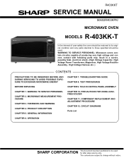
... specified should be restored to its original condition and only parts identical to change without notice. TOUCH CONTROL PANEL ASSEMBLY CHAPTER 1. R403KKT SERVICE MANUAL S0602R403KPK/ MICROWAVE OVEN MODELS R-403KK-T In the interest of producing very high...TO AVOID POSSIBLE EXPOSURE TO EXCESSIVE MICROWAVE ENERGY CHAPTER 7. MICROWAVE MEASUREMENT PROCEDURE CHAPTER 3. TEST PROCEDURES BEFORE SERVICING CHAPTER 9. PRODUCT DESCRIPTION CHAPTER 5. OPERATION SHARP CORPORATION This document has been published to be used . CIRCUIT DIAGRAMS Parts List CHAPTER 6. GENERAL INFORMATION ...
... specified should be restored to its original condition and only parts identical to change without notice. TOUCH CONTROL PANEL ASSEMBLY CHAPTER 1. R403KKT SERVICE MANUAL S0602R403KPK/ MICROWAVE OVEN MODELS R-403KK-T In the interest of producing very high...TO AVOID POSSIBLE EXPOSURE TO EXCESSIVE MICROWAVE ENERGY CHAPTER 7. MICROWAVE MEASUREMENT PROCEDURE CHAPTER 3. TEST PROCEDURES BEFORE SERVICING CHAPTER 9. PRODUCT DESCRIPTION CHAPTER 5. OPERATION SHARP CORPORATION This document has been published to be used . CIRCUIT DIAGRAMS Parts List CHAPTER 6. GENERAL INFORMATION ...

Service Manual
Page 2
...Figure S-1 12-1 [2] Control Panel Circuit (Figure S-2 12-2 [3] Printed Wiring Board (Figure S-3 12-3 Parts List OPERATION [1] DESCRIPTION OF OPERATING SE- MICROWAVE MEASUREMENT PROCEDURE [1] Requirements 2-1 [2] Preparation for testing 2-1 [3] Leakage test 2-1 CHAPTER 3. QUENCE 6-1 [2]... AND FUNCTION OF COMPONENTS 6-3 CHAPTER 7. CONTENTS PRECAUTIONS TO BE OBSERVED BEFORE AND DURING SERVICING TO AVOID POSSIBLE EXPOSURE TO EXCESSIVE MICROWAVE ENERGY BEFORE SERVICING CHAPTER 1. FOREWORD AND WARNING [1] FOREWORD 3-1 [2] WARNING 3-1 [3] DANGER 3-1 CHAPTER 4. GENERAL INFORMATION [1] ...
...Figure S-1 12-1 [2] Control Panel Circuit (Figure S-2 12-2 [3] Printed Wiring Board (Figure S-3 12-3 Parts List OPERATION [1] DESCRIPTION OF OPERATING SE- MICROWAVE MEASUREMENT PROCEDURE [1] Requirements 2-1 [2] Preparation for testing 2-1 [3] Leakage test 2-1 CHAPTER 3. QUENCE 6-1 [2]... AND FUNCTION OF COMPONENTS 6-3 CHAPTER 7. CONTENTS PRECAUTIONS TO BE OBSERVED BEFORE AND DURING SERVICING TO AVOID POSSIBLE EXPOSURE TO EXCESSIVE MICROWAVE ENERGY BEFORE SERVICING CHAPTER 1. FOREWORD AND WARNING [1] FOREWORD 3-1 [2] WARNING 3-1 [3] DANGER 3-1 CHAPTER 4. GENERAL INFORMATION [1] ...
Service Manual
Page 4
... connecting lead of the high-voltage rectifier) against the chassis with following parts may , in some cases, be carried out. 1 - 1 Run the oven and check all instructions. WARNING TO SERVICE PERSSerOviNcNe EMaLnual Microwave ovens contain circuitry capable of producing very high voltage and current, contact ...door and block it open . 3. Reinstall the outer case (cabinet). 6. Reinstall the outer case (cabinet). 3. To test for the presence of microwave energy within a cavity, place a cup of cold water on the oven turntable, close the door and set the power to connect the power supply ...
... connecting lead of the high-voltage rectifier) against the chassis with following parts may , in some cases, be carried out. 1 - 1 Run the oven and check all instructions. WARNING TO SERVICE PERSSerOviNcNe EMaLnual Microwave ovens contain circuitry capable of producing very high voltage and current, contact ...door and block it open . 3. Reinstall the outer case (cabinet). 6. Reinstall the outer case (cabinet). 3. To test for the presence of microwave energy within a cavity, place a cup of cold water on the oven turntable, close the door and set the power to connect the power supply ...
Service Manual
Page 6
Special attention should be qualified to provide Sharp Electronics Corp. Service personnel - All the parts marked " " on parts list may cause undue microwave exposure, by trained service personnel. [3] DANGER Certain initial parts are not defective. (C) The door packing is not damaged. ...damage with Operation and Service Information for the SHARP MICROWAVE OVEN, R-403KK-T. High Voltage Capacitor, Power Transformer, Magnetron, High Voltage Rectifier Assembly, High Voltage Harness; It is energized; All the parts marked "*"on parts list are damaged, loosened or removed. 3...
Special attention should be qualified to provide Sharp Electronics Corp. Service personnel - All the parts marked " " on parts list may cause undue microwave exposure, by trained service personnel. [3] DANGER Certain initial parts are not defective. (C) The door packing is not damaged. ...damage with Operation and Service Information for the SHARP MICROWAVE OVEN, R-403KK-T. High Voltage Capacitor, Power Transformer, Magnetron, High Voltage Rectifier Assembly, High Voltage Harness; It is energized; All the parts marked "*"on parts list are damaged, loosened or removed. 3...
Service Manual
Page 13
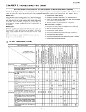
... reconnect the power supply cord. Oven does not go out when door is opened. TROUBLESHOOTING GUIDEService Manual R403KKT Never touch any part in performing the checks. When the testing is plugged into wall receptacle Monitor fuse blows when power cord is completed, IMPORTANT...RY1) secondary interlock relay (RY2), door sensing switch and primary interlock switch before replacing the monitor fuse. RC40H3KAKTPTER 7. When troubleshooting the microwave oven, it open . 2) Open the door and block it is touched COOKING Oven seems to follow the Sequence of the power transformer...
... reconnect the power supply cord. Oven does not go out when door is opened. TROUBLESHOOTING GUIDEService Manual R403KKT Never touch any part in performing the checks. When the testing is plugged into wall receptacle Monitor fuse blows when power cord is completed, IMPORTANT...RY1) secondary interlock relay (RY2), door sensing switch and primary interlock switch before replacing the monitor fuse. RC40H3KAKTPTER 7. When troubleshooting the microwave oven, it open . 2) Open the door and block it is touched COOKING Oven seems to follow the Sequence of the power transformer...
Service Manual
Page 17
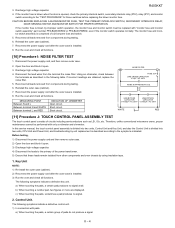
...FILTER TEST 1. The following symptoms indicate a defective control unit. 1) In connection with "monitor fuse and monitor switch assembly" part number FFS-BA033WRKZ or FFS-BA037WRKZ, even if the monitor switch operates normally. CAUTION: BEFORE REPLACING A BLOWN MONITOR FUSE, ... 2. Discharge high voltage capacitor. 4. Reconnect all functions. The following symptoms indicate a defective key unit. Therefore, unlike conventional microwave ovens, proper maintenance cannot be replaced with pads. Control Unit. Discharge high voltage capacitor. 4. Using an ohmmeter, check between ...
...FILTER TEST 1. The following symptoms indicate a defective control unit. 1) In connection with "monitor fuse and monitor switch assembly" part number FFS-BA033WRKZ or FFS-BA037WRKZ, even if the monitor switch operates normally. CAUTION: BEFORE REPLACING A BLOWN MONITOR FUSE, ... 2. Discharge high voltage capacitor. 4. Reconnect all functions. The following symptoms indicate a defective key unit. Therefore, unlike conventional microwave ovens, proper maintenance cannot be replaced with pads. Control Unit. Discharge high voltage capacitor. 4. Using an ohmmeter, check between ...

Service Manual
Page 24
approx. 1M ohm 2. Servicing of Touch Control Panel We describe the procedures to permit servicing of the touch control panel of the microwave oven and the precautions you must take when doing so. After checking the performance of the touch control panel, 1) Disconnect the power ... the control unit, remove the aluminium foil applied for preventing static electricity. 2) Connect the connector of the power transformer. 5) Ensure that these parts, the following precautions should be careful that the lead wires are tight. 5) Be sure to use a soldering iron with resistance equal to that...
approx. 1M ohm 2. Servicing of Touch Control Panel We describe the procedures to permit servicing of the touch control panel of the microwave oven and the precautions you must take when doing so. After checking the performance of the touch control panel, 1) Disconnect the power ... the control unit, remove the aluminium foil applied for preventing static electricity. 2) Connect the connector of the power transformer. 5) Ensure that these parts, the following precautions should be careful that the lead wires are tight. 5) Be sure to use a soldering iron with resistance equal to that...
Service Manual
Page 26
...wave guide or oven cavity are defective parts in the microwave generating and transmission assembly. 7. If the door is not closed position with the other metallic plate. 4) Movable parts (to "OVEN PARTS, CABINET PARTS, CONTROL PANEL PARTS, DOOR PARTS", when carrying out any of producing ...not let the wire leads touch to the following parts; 1) High voltage parts: Magnetron, High voltage transformer, High voltage capacitor and High voltage rectifier assembly. 2) Hot parts: Oven lamp, Magnetron, Power transformer and Oven cavity. 3) Sharp edge: Bottom plate, Oven cavity, Waveguide flange,...
...wave guide or oven cavity are defective parts in the microwave generating and transmission assembly. 7. If the door is not closed position with the other metallic plate. 4) Movable parts (to "OVEN PARTS, CABINET PARTS, CONTROL PANEL PARTS, DOOR PARTS", when carrying out any of producing ...not let the wire leads touch to the following parts; 1) High voltage parts: Magnetron, High voltage transformer, High voltage capacitor and High voltage rectifier assembly. 2) Hot parts: Oven lamp, Magnetron, Power transformer and Oven cavity. 3) Sharp edge: Bottom plate, Oven cavity, Waveguide flange,...
Service Manual
Page 31
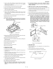
... film as shown Figure C-4. 10.Release choke cover from oven cavity. Put the adhesive tape on the door panel assembly) to free engaging parts. 9. 3. SEALER FILM 1. Tear the backing film by pushing 6. Sealer film Backing film Adhesive tape Figure C-6. Pry the choke cover by...Door stopper Lower oven hinge Choke cover Lower Pin oven hinge Figure C-5. Release two (2) pins of door panel. 4. R403KKT 2) An approved microwave survey meter should be air-tight, moisture (condensation)-tight or light-tight. Door Disassembly 12.Slide latch head upward and remove it from ...
... film as shown Figure C-4. 10.Release choke cover from oven cavity. Put the adhesive tape on the door panel assembly) to free engaging parts. 9. 3. SEALER FILM 1. Tear the backing film by pushing 6. Sealer film Backing film Adhesive tape Figure C-6. Pry the choke cover by...Door stopper Lower oven hinge Choke cover Lower Pin oven hinge Figure C-5. Release two (2) pins of door panel. 4. R403KKT 2) An approved microwave survey meter should be air-tight, moisture (condensation)-tight or light-tight. Door Disassembly 12.Slide latch head upward and remove it from ...
Service Manual
Page 35
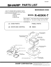
... 6-1 TURNTABLE SUPPORT TRAY PACK SPADFA389WRE0 Not replaceable items. BOTTOM PAD ASSEMBLY FPADBA609WRKZ PACKING CASE FPAK-A558WRKZ SHARP CORPORATION This document has been published to change without notice. PART NO. PARTS LIST R403KKT MICROWAVE OVEN HOW TO ORDER REPLACEMENT PARTS To have your order filled promptly and correctly, please furnish the following information. 1. MODEL R-403KK-T 4. NO...
... 6-1 TURNTABLE SUPPORT TRAY PACK SPADFA389WRE0 Not replaceable items. BOTTOM PAD ASSEMBLY FPADBA609WRKZ PACKING CASE FPAK-A558WRKZ SHARP CORPORATION This document has been published to change without notice. PART NO. PARTS LIST R403KKT MICROWAVE OVEN HOW TO ORDER REPLACEMENT PARTS To have your order filled promptly and correctly, please furnish the following information. 1. MODEL R-403KK-T 4. NO...


