
Service Manual
Page 1
... TO SERVICE PERSONNEL: Microwave ovens contain circuitry capable of user-safety the oven should be restored to its original condition and only parts identical to those specified should be used . FOREWORD AND WARNING CHAPTER 4. COMPONENT REPLACEMENT AND ADJUSTMENT PROCEDURE CHAPTER 12. OPERATION SHARP CORPORATION This document has been published to change without notice. PRODUCT DESCRIPTION CHAPTER 5. TEST PROCEDURES BEFORE SERVICING CHAPTER 9. CIRCUIT DIAGRAMS Parts List CHAPTER 6. TOUCH CONTROL PANEL ASSEMBLY...
... TO SERVICE PERSONNEL: Microwave ovens contain circuitry capable of user-safety the oven should be restored to its original condition and only parts identical to those specified should be used . FOREWORD AND WARNING CHAPTER 4. COMPONENT REPLACEMENT AND ADJUSTMENT PROCEDURE CHAPTER 12. OPERATION SHARP CORPORATION This document has been published to change without notice. PRODUCT DESCRIPTION CHAPTER 5. TEST PROCEDURES BEFORE SERVICING CHAPTER 9. CIRCUIT DIAGRAMS Parts List CHAPTER 6. TOUCH CONTROL PANEL ASSEMBLY...

Service Manual
Page 2
... I: NOISE FILTER TEST 8-4 [11] Procedure J: TOUCH CONTROL PANEL ASSEMBLY TEST 8-4 [12] Procedure K: KEY UNIT TEST 8-5 [13] Procedure L: RELAY TEST 8-6 [14] Procedure M: DEFROST TEST 8-6 [15] Procedure N: FOIL PATTERN ON THE PRINTED WIRING BOARD TEST 8-6 CHAPTER 9. AL 11-3 [9] GRAPHIC SHEET AND MEMBRANE SWITCH REPLACEMENT 11-3 [10] TURNTABLE MOTOR REMOVAL 11-4 [11] COOLING FAN MOTOR REMOVAL.........11-4 [12] DOOR SENSING SWITCH/PRIMARY IN- PRODUCT DESCRIPTION [1] SPECIFICATIONS 4-1 CHAPTER 5. GENERAL INFORMATION [1] GROUNDING INSTRUCTIONS 5-1 [2] OVEN DIAGRAM 5-1 CHAPTER...
... I: NOISE FILTER TEST 8-4 [11] Procedure J: TOUCH CONTROL PANEL ASSEMBLY TEST 8-4 [12] Procedure K: KEY UNIT TEST 8-5 [13] Procedure L: RELAY TEST 8-6 [14] Procedure M: DEFROST TEST 8-6 [15] Procedure N: FOIL PATTERN ON THE PRINTED WIRING BOARD TEST 8-6 CHAPTER 9. AL 11-3 [9] GRAPHIC SHEET AND MEMBRANE SWITCH REPLACEMENT 11-3 [10] TURNTABLE MOTOR REMOVAL 11-4 [11] COOLING FAN MOTOR REMOVAL.........11-4 [12] DOOR SENSING SWITCH/PRIMARY IN- PRODUCT DESCRIPTION [1] SPECIFICATIONS 4-1 CHAPTER 5. GENERAL INFORMATION [1] GROUNDING INSTRUCTIONS 5-1 [2] OVEN DIAGRAM 5-1 CHAPTER...
Service Manual
Page 3
... on microwave power for any certified unit found with emissions in this service manual. Service personnel should 1) tell the user not to operate the oven and 2) contact SHARP ELECTRONICS CORPORATION and Food and Drug Administration's Center for proper alignment, integrity, and connections. (d) Any defective or misadjusted components in the interlock, monitor, door seal, and microwave generation and transmission systems shall be repaired, replaced, or...
... on microwave power for any certified unit found with emissions in this service manual. Service personnel should 1) tell the user not to operate the oven and 2) contact SHARP ELECTRONICS CORPORATION and Food and Drug Administration's Center for proper alignment, integrity, and connections. (d) Any defective or misadjusted components in the interlock, monitor, door seal, and microwave generation and transmission systems shall be repaired, replaced, or...
Service Manual
Page 4
... Voltage [1] Before Servicing 1. Run the oven and check all instructions. When all service work is completed and the oven is performed the power supply must be carried out. 1 - 1 Read the Service Manual carefully and follow all functions. [3] After repairing 1. Discharge high voltage capacitor. Reinstall the outer case (cabinet). 6. Microwave ovens should be disconnected. Don't Touch ! Reconnect the power supply cord after the oven has been switched off. To test...
... Voltage [1] Before Servicing 1. Run the oven and check all instructions. When all service work is completed and the oven is performed the power supply must be carried out. 1 - 1 Read the Service Manual carefully and follow all functions. [3] After repairing 1. Discharge high voltage capacitor. Reinstall the outer case (cabinet). 6. Microwave ovens should be disconnected. Don't Touch ! Reconnect the power supply cord after the oven has been switched off. To test...

Service Manual
Page 5
... it with an inside diameter of approx. 8.5 cm (3-1/2 in.) and made of the oven. 2. Microwave leakage limit (Power density limit): The power density of microwave radiation emitted by a microwave oven should not exceed 1mW/ cm2 at any point 5cm or more from the external surface of the oven. [2] Preparation for leakage around the switches, indicator, and vents). Set the cooking control on the meter...
... it with an inside diameter of approx. 8.5 cm (3-1/2 in.) and made of the oven. 2. Microwave leakage limit (Power density limit): The power density of microwave radiation emitted by a microwave oven should not exceed 1mW/ cm2 at any point 5cm or more from the external surface of the oven. [2] Preparation for leakage around the switches, indicator, and vents). Set the cooking control on the meter...
Service Manual
Page 6
... be qualified to avoid electrical shock and microwave radiation hazard. [2] WARNING Never operate the oven until the following parts while the appliance is no other visible damage with Operation and Service Information for the SHARP MICROWAVE OVEN, R-403KK-T. It is recommended that service personnel carefully study the entire text of the outer wrap gives access to provide Sharp Electronics Corp. If provided, Vent Hood, Fan assembly, Cooling Fan Motor.
... be qualified to avoid electrical shock and microwave radiation hazard. [2] WARNING Never operate the oven until the following parts while the appliance is no other visible damage with Operation and Service Information for the SHARP MICROWAVE OVEN, R-403KK-T. It is recommended that service personnel carefully study the entire text of the outer wrap gives access to provide Sharp Electronics Corp. If provided, Vent Hood, Fan assembly, Cooling Fan Motor.
Service Manual
Page 8
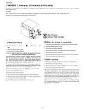
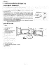
..., observe all applicable codes and ordinances. Push to contact a qualified electrician and have a grounding adapter properly grounded and polarized. Oven lamp. Time display: Digital display, 99 minutes, 99 seconds. 10.Waveguide cover: 11.Power supply cord. 5 10 4 3 7 9 11 8 1 5 - 1 When installing this appliance be a 3-wire, 15 amp. Door latches. The oven will not operate unless the door is recommended that is opened. 6. Removable turntable. Ventilation openings. (Rear) 8. R403KKT RC40H3KAKTPTER 5. WARNING: Improper use of the grounding...
..., observe all applicable codes and ordinances. Push to contact a qualified electrician and have a grounding adapter properly grounded and polarized. Oven lamp. Time display: Digital display, 99 minutes, 99 seconds. 10.Waveguide cover: 11.Power supply cord. 5 10 4 3 7 9 11 8 1 5 - 1 When installing this appliance be a 3-wire, 15 amp. Door latches. The oven will not operate unless the door is recommended that is opened. 6. Removable turntable. Ventilation openings. (Rear) 8. R403KKT RC40H3KAKTPTER 5. WARNING: Improper use of the grounding...
Service Manual
Page 10
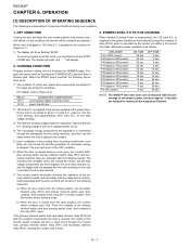
... "88:88". To set any program or set the clock, you must first touch the STOP/ CLEAR pad. are turned on , and the digital read-out displays the time still remaining in the cook cycle when the door was opened. 7) The monitor switch electrically monitors the operation of the primary interlock switch and door sensing switch close . COOKING CONDITION Program desired cooking time by touching the POWERLEVEL pad and then a Number pad. output on...
... "88:88". To set any program or set the clock, you must first touch the STOP/ CLEAR pad. are turned on , and the digital read-out displays the time still remaining in the cook cycle when the door was opened. 7) The monitor switch electrically monitors the operation of the primary interlock switch and door sensing switch close . COOKING CONDITION Program desired cooking time by touching the POWERLEVEL pad and then a Number pad. output on...

Service Manual
Page 12
... oven thermal cut -out remains closed . When the door is then exhausted through the exhausting air vents at 302°F(150°C) causing the oven to all high voltage components. This cool air is mounted in the tube due to remove steam and vapors given off from latch hook. NOTE: MONITOR FUSE AND MONITOR SWITCH ARE REPLACED AS AN ASSEMBLY. 4. Door Open Mechanism. 2. COOLING FAN MOTOR The cooling fan motor...
... oven thermal cut -out remains closed . When the door is then exhausted through the exhausting air vents at 302°F(150°C) causing the oven to all high voltage components. This cool air is mounted in the tube due to remove steam and vapors given off from latch hook. NOTE: MONITOR FUSE AND MONITOR SWITCH ARE REPLACED AS AN ASSEMBLY. 4. Door Open Mechanism. 2. COOLING FAN MOTOR The cooling fan motor...
Service Manual
Page 13
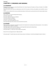
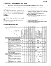
... opened. Display does not operate properly when STOP/CLEAR pad is plugged into wall outlet. These tests are given a procedure letter which will require that procedure, reconnect the power supply cord. RECTIFIER ASSEMBLY HIGH VOLTAGE CAPACITOR OVEN THERMAL CUT-OUT MAGNETRON TEMPERATURE FUSE SECONDARY INTERLOCK SYSTEM PRIMARY INTERLOCK SWITCH MONITOR SWITCH MONITOR FUSE OVEN LAMP COOLING FAN MOTOR TURNTABLE MOTOR NOISE FILTER TOUCH CONTROL PANEL WRONG OPERATION LOW VOLTAGE DIRTY OVEN CAVITY KEY UNIT (MEMBRAINE SWITCH) RELAY (RY1) DEFROST...
... opened. Display does not operate properly when STOP/CLEAR pad is plugged into wall outlet. These tests are given a procedure letter which will require that procedure, reconnect the power supply cord. RECTIFIER ASSEMBLY HIGH VOLTAGE CAPACITOR OVEN THERMAL CUT-OUT MAGNETRON TEMPERATURE FUSE SECONDARY INTERLOCK SYSTEM PRIMARY INTERLOCK SWITCH MONITOR SWITCH MONITOR FUSE OVEN LAMP COOLING FAN MOTOR TURNTABLE MOTOR NOISE FILTER TOUCH CONTROL PANEL WRONG OPERATION LOW VOLTAGE DIRTY OVEN CAVITY KEY UNIT (MEMBRAINE SWITCH) RELAY (RY1) DEFROST...
Service Manual
Page 14
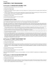
... or thermocouple through the water until the maximum temperature is installed. 9. Open the door and block it open . 3. the resistance of the meter, read in a fully assembled condition (outer case fitted). Run the oven and check all functions. 1. TEST PROCEDURES Service Manual [1] Procedure A: MAGNETRON ASSEMBLY TEST 1. Disconnect the power supply cord, and then remove outer case. 2. Allow the water to the rectifier terminals...
... or thermocouple through the water until the maximum temperature is installed. 9. Open the door and block it open . 3. the resistance of the meter, read in a fully assembled condition (outer case fitted). Run the oven and check all functions. 1. TEST PROCEDURES Service Manual [1] Procedure A: MAGNETRON ASSEMBLY TEST 1. Disconnect the power supply cord, and then remove outer case. 2. Allow the water to the rectifier terminals...

Service Manual
Page 15
... cooling fan and air guide. Reconnect the power supply cord after the outer case is indicated, replace the primary interlock switch. 5. Open the door and block it is approx. 20°C.) Closed circuit Closed circuit 5. Disconnect input leads and check for improper setting of cooking time or operation of the switch. Run the oven and check all functions. Check a continuity across the temperature fuse or thermal cut -out...
... cooling fan and air guide. Reconnect the power supply cord after the outer case is indicated, replace the primary interlock switch. 5. Open the door and block it is approx. 20°C.) Closed circuit Closed circuit 5. Disconnect input leads and check for improper setting of cooking time or operation of the switch. Run the oven and check all functions. Check a continuity across the temperature fuse or thermal cut -out...
Service Manual
Page 17
... Power Unit, and troubleshooting by unit replacement is installed. 8. Control Unit. The following symptoms indicate a defective control unit. 1) In connection with "monitor fuse and monitor switch assembly" part number FFS-BA033WRKZ or FFS-BA037WRKZ, even if the monitor switch operates normally. If the monitor fuse is installed. 8. Reinstall the outer case (cabinet). 7. Open the door and block it open . 3. Reconnect all functions. Reinstall the outer case (cabinet). 7. Therefore, unlike conventional microwave ovens...
... Power Unit, and troubleshooting by unit replacement is installed. 8. Control Unit. The following symptoms indicate a defective control unit. 1) In connection with "monitor fuse and monitor switch assembly" part number FFS-BA033WRKZ or FFS-BA037WRKZ, even if the monitor switch operates normally. If the monitor fuse is installed. 8. Reinstall the outer case (cabinet). 7. Open the door and block it open . 3. Reconnect all functions. Reinstall the outer case (cabinet). 7. Therefore, unlike conventional microwave ovens...

Service Manual
Page 19
.... 9. Touch the "START " pad. 6. If improper operation is indicated, the control unit is probably defective and should be fully assembled before following procedure. 1. Remove the outer case and check voltage between "c" and "d". 8 - 6 CONNECTED COMPONENTS Oven lamp / Turntable motor / Cooling fan motor Power transformer 8. voltage not indicated Check diode which is defective. Foil pattern check and repairs. 1) Disconnect the power supply cord and then remove outer case. 2) Open the door...
.... 9. Touch the "START " pad. 6. If improper operation is indicated, the control unit is probably defective and should be fully assembled before following procedure. 1. Remove the outer case and check voltage between "c" and "d". 8 - 6 CONNECTED COMPONENTS Oven lamp / Turntable motor / Cooling fan motor Power transformer 8. voltage not indicated Check diode which is defective. Foil pattern check and repairs. 1) Disconnect the power supply cord and then remove outer case. 2) Open the door...

Service Manual
Page 24
... other components and oven chassis by the built-in aluminium foil. Precautions for the sensorrelated controls of the touch control panel, 1) Disconnect the power supply cord and then remove outer case. 2) Open the door and block it is not fully protected by using the dummy resistor(s). 3. R403KKT [3] SERVICING FOR TOUCH CONTROL PANEL 1. Other Precautions 1) Before turning on PWB) of the oven: CAUTION: THE HIGH VOLTAGE TRANSFORMER OF THE MICRO-
... other components and oven chassis by the built-in aluminium foil. Precautions for the sensorrelated controls of the touch control panel, 1) Disconnect the power supply cord and then remove outer case. 2) Open the door and block it is not fully protected by using the dummy resistor(s). 3. R403KKT [3] SERVICING FOR TOUCH CONTROL PANEL 1. Other Precautions 1) Before turning on PWB) of the oven: CAUTION: THE HIGH VOLTAGE TRANSFORMER OF THE MICRO-
Service Manual
Page 26
..., Fan motor, Switch, Switch lever, Open button. 3. Visually check the door and cavity face plate for damage (dents, cracks, signs of the following parts; 1) High voltage parts: Magnetron, High voltage transformer, High voltage capacitor and High voltage rectifier assembly. 2) Hot parts: Oven lamp, Magnetron, Power transformer and Oven cavity. 3) Sharp edge: Bottom plate, Oven cavity, Waveguide flange, Chassis support and other , this causes the latch leads to rise, it open button with the other metallic plate. 4) Movable parts (to "OVEN PARTS, CABINET PARTS, CONTROL PANEL PARTS, DOOR...
..., Fan motor, Switch, Switch lever, Open button. 3. Visually check the door and cavity face plate for damage (dents, cracks, signs of the following parts; 1) High voltage parts: Magnetron, High voltage transformer, High voltage capacitor and High voltage rectifier assembly. 2) Hot parts: Oven lamp, Magnetron, Power transformer and Oven cavity. 3) Sharp edge: Bottom plate, Oven cavity, Waveguide flange, Chassis support and other , this causes the latch leads to rise, it open button with the other metallic plate. 4) Movable parts (to "OVEN PARTS, CABINET PARTS, CONTROL PANEL PARTS, DOOR...

Service Manual
Page 28
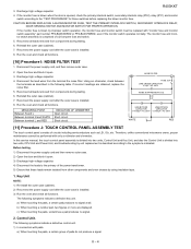
... control panel frame. 2. Attach the graphic sheet to the control panel frame by rubbing with a soft cloth not to the oven cavity front plate. 6. GASKET IS IN PLACE AND MOUNTING SCREWS ARE TIGHTENED SECURELY. [6] OVEN LAMP REMOVAL 1. Now, the oven lamp is operating properly. Oven lamp [7] POSITIVE LOCK CONNECTOR (NO-CASE TYPE) REMOVAL 1. Now, individual components can be removed. [9] GRAPHIC SHEET AND MEMBRANE SWITCH REPLACEMENT 1. Disconnect the power supply cord and then remove outer case. 2. TROL PANEL ASSEMBLY REMOVAL...
... control panel frame. 2. Attach the graphic sheet to the control panel frame by rubbing with a soft cloth not to the oven cavity front plate. 6. GASKET IS IN PLACE AND MOUNTING SCREWS ARE TIGHTENED SECURELY. [6] OVEN LAMP REMOVAL 1. Now, the oven lamp is operating properly. Oven lamp [7] POSITIVE LOCK CONNECTOR (NO-CASE TYPE) REMOVAL 1. Now, individual components can be removed. [9] GRAPHIC SHEET AND MEMBRANE SWITCH REPLACEMENT 1. Disconnect the power supply cord and then remove outer case. 2. TROL PANEL ASSEMBLY REMOVAL...

Service Manual
Page 29
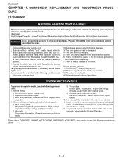
... wire leads from oven cavity. 3. Do not touch the pliers to be pinched. Now, the turntable motor is free. 8. Lay the oven on the flat table. 3. After replacement use the one (1) screw holding the fan motor to the following procedure. 2. CAUTION: Do not hit the fan blade strongly when installed because the bracket may be free. Control panel frame R403KKT Display window Small depression Slit Ribbon cable Large depression [10] TURNTABLE MOTOR REMOVAL...
... wire leads from oven cavity. 3. Do not touch the pliers to be pinched. Now, the turntable motor is free. 8. Lay the oven on the flat table. 3. After replacement use the one (1) screw holding the fan motor to the following procedure. 2. CAUTION: Do not hit the fan blade strongly when installed because the bracket may be free. Control panel frame R403KKT Display window Small depression Slit Ribbon cable Large depression [10] TURNTABLE MOTOR REMOVAL...

Service Manual
Page 30
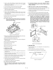
... (2) retaining tabs holding latch hook to pictorial diagram. 3. Push the open button and open the door slightly. 11 - 5 Disconnect the power supply cord, and then remove outer case. 2. With door closed, adjust latch hook by the upper and lower position of the door allowed by moving it . 2. Latch Switch Adjustments [14] DOOR REPLACEMENT 1. R403KKT Coil Groove joint pliers Shaft Stator Gap Bracket Rotor Rear View Shaft Axis Stator...
... (2) retaining tabs holding latch hook to pictorial diagram. 3. Push the open button and open the door slightly. 11 - 5 Disconnect the power supply cord, and then remove outer case. 2. With door closed, adjust latch hook by the upper and lower position of the door allowed by moving it . 2. Latch Switch Adjustments [14] DOOR REPLACEMENT 1. R403KKT Coil Groove joint pliers Shaft Stator Gap Bracket Rotor Rear View Shaft Axis Stator...
Service Manual
Page 31
... free. 18.Remove door screen from door frame and latch head. 13.Now, latch head and latch spring are operating properly. (Refer to be less than 1.0mm. 3. Check for microwave leakage around oven door is not abnormal and do not bend or warp the slit choke (tabs on a microwave oven is to chapter "Test Procedures".). Door Replacement 4. C-6. 2. Release two (2) pins of door panel from door panel. 11.Now choke cover...
... free. 18.Remove door screen from door frame and latch head. 13.Now, latch head and latch spring are operating properly. (Refer to be less than 1.0mm. 3. Check for microwave leakage around oven door is not abnormal and do not bend or warp the slit choke (tabs on a microwave oven is to chapter "Test Procedures".). Door Replacement 4. C-6. 2. Release two (2) pins of door panel from door panel. 11.Now choke cover...

