
Service Manual
Page 1
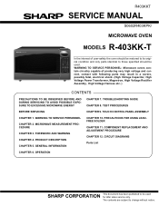
...CHAPTER 1. COMPONENT REPLACEMENT AND ADJUSTMENT PROCEDURE CHAPTER 12. OPERATION SHARP CORPORATION This document has been published to be used for after sales service only. WARNING TO SERVICE PERSONNEL: Microwave ovens contain circuitry capable of user-safety the oven should be...change without notice. TROUBLESHOOTING GUIDE CHAPTER 8. WARNING TO SERVICE PERSONNEL CHAPTER 2. MICROWAVE MEASUREMENT PROCEDURE CHAPTER 3. PRECAUTIONS FOR USING LEADFREE SOLDER CHAPTER 11. R403KKT SERVICE MANUAL S0602R403KPK/ MICROWAVE OVEN MODELS R-403KK-T In the interest of producing very high voltage and ...
...CHAPTER 1. COMPONENT REPLACEMENT AND ADJUSTMENT PROCEDURE CHAPTER 12. OPERATION SHARP CORPORATION This document has been published to be used for after sales service only. WARNING TO SERVICE PERSONNEL: Microwave ovens contain circuitry capable of user-safety the oven should be...change without notice. TROUBLESHOOTING GUIDE CHAPTER 8. WARNING TO SERVICE PERSONNEL CHAPTER 2. MICROWAVE MEASUREMENT PROCEDURE CHAPTER 3. PRECAUTIONS FOR USING LEADFREE SOLDER CHAPTER 11. R403KKT SERVICE MANUAL S0602R403KPK/ MICROWAVE OVEN MODELS R-403KK-T In the interest of producing very high voltage and ...

Service Manual
Page 2
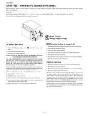
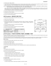
...PANEL 9-4 CHAPTER 10. CONTENTS PRECAUTIONS TO BE OBSERVED BEFORE AND DURING SERVICING TO AVOID POSSIBLE EXPOSURE TO EXCESSIVE MICROWAVE ENERGY BEFORE SERVICING CHAPTER 1. WARNING TO SERVICE PERSONNEL [1] Before Servicing 1-1 [2] When the testing is completed... 4. TEST PROCEDURES [1] Procedure A: MAGNETRON ASSEMBLY TEST 8-1 [2] Procedure B: POWER TRANSFORMER TEST 8-1 [3] Procedure C: HIGH VOLTAGE RECTIFI- MICROWAVE MEASUREMENT PROCEDURE [1] Requirements 2-1 [2] Preparation for testing 2-1 [3] Leakage test 2-1 CHAPTER 3. PRECAUTIONS FOR USING LEADFREE SOLDER [1] Employing lead...
...PANEL 9-4 CHAPTER 10. CONTENTS PRECAUTIONS TO BE OBSERVED BEFORE AND DURING SERVICING TO AVOID POSSIBLE EXPOSURE TO EXCESSIVE MICROWAVE ENERGY BEFORE SERVICING CHAPTER 1. WARNING TO SERVICE PERSONNEL [1] Before Servicing 1-1 [2] When the testing is completed... 4. TEST PROCEDURES [1] Procedure A: MAGNETRON ASSEMBLY TEST 8-1 [2] Procedure B: POWER TRANSFORMER TEST 8-1 [3] Procedure C: HIGH VOLTAGE RECTIFI- MICROWAVE MEASUREMENT PROCEDURE [1] Requirements 2-1 [2] Preparation for testing 2-1 [3] Leakage test 2-1 CHAPTER 3. PRECAUTIONS FOR USING LEADFREE SOLDER [1] Employing lead...
Service Manual
Page 3
...to verify compliance with the Federal Performance Standard should be performed on microwave power for any certified unit found with emissions in excess of the specified limit, contact SHARP ELECTRONICS CORPORATION immediately @1-800-237-4277. The owner of dropping or... described in this service manual. Service personnel should inform SHARP ELECTRONICS CORPORATION of 4mW/cm2. If microwave emissions level is released to the own. BEFOR SERVICING BEFORE SERVICING Before servicing an operative unit, perform a microwave emission check as necessary: (1) interlock operation, (2) proper...
...to verify compliance with the Federal Performance Standard should be performed on microwave power for any certified unit found with emissions in excess of the specified limit, contact SHARP ELECTRONICS CORPORATION immediately @1-800-237-4277. The owner of dropping or... described in this service manual. Service personnel should inform SHARP ELECTRONICS CORPORATION of 4mW/cm2. If microwave emissions level is released to the own. BEFOR SERVICING BEFORE SERVICING Before servicing an operative unit, perform a microwave emission check as necessary: (1) interlock operation, (2) proper...
Service Manual
Page 4
...supply cord after the outer case has been removed, in some cases, be disconnected. R403KKT RC40H3KAKTPTER 1. WARNING TO SERVICE PERSSerOviNcNe EMaLnual Microwave ovens contain circuitry capable of producing very high voltage and current, contact with the use of the power transformer. 5) Ensure that ...60 seconds and then short-circuit the connection of cold water on the oven turntable, close the door and set the microwave timer for the presence of microwave energy within a cavity, place a cup of the high-voltage capacitor (that the water is completed, 1. Reinstall the...
...supply cord after the outer case has been removed, in some cases, be disconnected. R403KKT RC40H3KAKTPTER 1. WARNING TO SERVICE PERSSerOviNcNe EMaLnual Microwave ovens contain circuitry capable of producing very high voltage and current, contact with the use of the power transformer. 5) Ensure that ...60 seconds and then short-circuit the connection of cold water on the oven turntable, close the door and set the microwave timer for the presence of microwave energy within a cavity, place a cup of the high-voltage capacitor (that the water is completed, 1. Reinstall the...

Service Manual
Page 5
...turn the oven OFF before the survey is completed, replace it perpendicular to insure that the actual instrument is permitted by the performance standard for microwave ovens, 21 CFR 1030.10(c)(3)(i), must be a low form of 600 ml (20 oz) beaker with 275 ml of the requirement as... prescribed by the closed latch assembly. 4. Safety interlock switches: Primary interlock switch shall prevent microwave radiation emission in .) and made of the oven. 2. If the water begins to boil before any leakage is important not only to protect the...
...turn the oven OFF before the survey is completed, replace it perpendicular to insure that the actual instrument is permitted by the performance standard for microwave ovens, 21 CFR 1030.10(c)(3)(i), must be a low form of 600 ml (20 oz) beaker with 275 ml of the requirement as... prescribed by the closed latch assembly. 4. Safety interlock switches: Primary interlock switch shall prevent microwave radiation emission in .) and made of the oven. 2. If the water begins to boil before any leakage is important not only to protect the...
Service Manual
Page 6
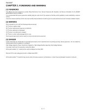
.... (D) The door is not deformed or warped. (E) There is energized; Special attention should be qualified to avoid electrical shock and microwave radiation hazard. [2] WARNING Never operate the oven until the following parts while the appliance is no other visible damage with Operation and ...Service Information for the SHARP MICROWAVE OVEN, R-403KK-T. Service Personnel with the oven. Servicing and repair work must be carried out only by themselves, or when they...
.... (D) The door is not deformed or warped. (E) There is energized; Special attention should be qualified to avoid electrical shock and microwave radiation hazard. [2] WARNING Never operate the oven until the following parts while the appliance is no other visible damage with Operation and ...Service Information for the SHARP MICROWAVE OVEN, R-403KK-T. Service Personnel with the oven. Servicing and repair work must be carried out only by themselves, or when they...
Service Manual
Page 7
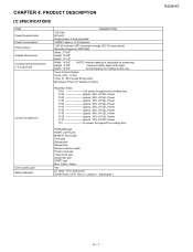
Touch Control System Clock (1:00 - 12:59) Timer (0 - 99 minutes 99 seconds) Microwave Power for holding food is calculated by measuring Height 9-3/8" maximum width, depth and height. P-HI Full power throughout the cooking time P-90 approx. 90% of ... FULL Power P-40 approx. 30% of FULL Power P-30 approx. 40% of FULL Power P-20 approx. 20% of FULL Power P-10 approx. 10% of RF microwave energy (IEC Test procedure) Operating frequency 2450 MHz Width 21-5/8" Height 12-3/8" Depth 17-1/2" Width 15-3/8" NOTE: Internal capacity is less. Depth 16-3/4" Actual capacity...
Touch Control System Clock (1:00 - 12:59) Timer (0 - 99 minutes 99 seconds) Microwave Power for holding food is calculated by measuring Height 9-3/8" maximum width, depth and height. P-HI Full power throughout the cooking time P-90 approx. 90% of ... FULL Power P-40 approx. 30% of FULL Power P-30 approx. 40% of FULL Power P-20 approx. 20% of FULL Power P-10 approx. 10% of RF microwave energy (IEC Test procedure) Operating frequency 2450 MHz Width 21-5/8" Height 12-3/8" Depth 17-1/2" Width 15-3/8" NOTE: Internal capacity is less. Depth 16-3/4" Actual capacity...
Service Manual
Page 10
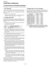
...activates the door sensing switch and primary interlock switch. (In this condition, the monitor switch contacts are opened , the closing of microwave energy is programmed, the 120 volts A.C. is plugged in, 120 volts A.C. COOKING CONDITION Program desired cooking time by touching the POWERLEVEL ... relay (RY2) and primary interlock switch open first. NOTE: The ON/OFF time ratio does not correspond with the percentage of microwave power, because approx. 3 seconds are activated with the following is mechanically associated with the contacts closed from the closed . winding ...
...activates the door sensing switch and primary interlock switch. (In this condition, the monitor switch contacts are opened , the closing of microwave energy is programmed, the 120 volts A.C. is plugged in, 120 volts A.C. COOKING CONDITION Program desired cooking time by touching the POWERLEVEL ... relay (RY2) and primary interlock switch open first. NOTE: The ON/OFF time ratio does not correspond with the percentage of microwave power, because approx. 3 seconds are activated with the following is mechanically associated with the contacts closed from the closed . winding ...
Service Manual
Page 13
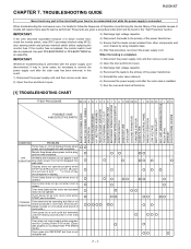
When troubleshooting the microwave oven, it open. 3) Discharge high voltage capacitor. 4) Reconnect the leads to the primary of a blown monitor fuse, check the monitor switch, relay (RY1) secondary interlock ...
When troubleshooting the microwave oven, it open. 3) Discharge high voltage capacitor. 4) Reconnect the leads to the primary of a blown monitor fuse, check the monitor switch, relay (RY1) secondary interlock ...
Service Manual
Page 14
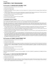
...terminals and observe, reverse the leads to the rectifier terminals and observe meter reading. Reinstall the outer case (cabinet). 8. MICROWAVE OUTPUT POWER The following test procedure should be measured by performing a water temperature rise test. HIGH VOLTAGES ARE PRESENT DURING THE...Check for 60 seconds, measuring with a thermometer or thermocouple tempera- On the R x 1 scale, the resistance of the coils with the microwave oven in tempera- Disconnect the power supply cord, and then remove outer case. 2. TEST PROCEDURES Service Manual [1] Procedure A: MAGNETRON ASSEMBLY TEST ...
...terminals and observe, reverse the leads to the rectifier terminals and observe meter reading. Reinstall the outer case (cabinet). 8. MICROWAVE OUTPUT POWER The following test procedure should be measured by performing a water temperature rise test. HIGH VOLTAGES ARE PRESENT DURING THE...Check for 60 seconds, measuring with a thermometer or thermocouple tempera- On the R x 1 scale, the resistance of the coils with the microwave oven in tempera- Disconnect the power supply cord, and then remove outer case. 2. TEST PROCEDURES Service Manual [1] Procedure A: MAGNETRON ASSEMBLY TEST ...
Service Manual
Page 17
... do not produce a signal. 8 - 4 Discharge high voltage capacitor. 4. b) When touching a number pad, two figures or more are obtained, replace the noise filter. 5. Therefore, unlike conventional microwave ovens, proper maintenance cannot be replaced with pads. MEASURING POINT Between N and L Between terminal N and WHITE Between terminal L and RED INDICATION OF OHMMETER Open circuit...
... do not produce a signal. 8 - 4 Discharge high voltage capacitor. 4. b) When touching a number pad, two figures or more are obtained, replace the noise filter. 5. Therefore, unlike conventional microwave ovens, proper maintenance cannot be replaced with pads. MEASURING POINT Between N and L Between terminal N and WHITE Between terminal L and RED INDICATION OF OHMMETER Open circuit...

Service Manual
Page 19
After that these leads remain isolated from components during the microwave cooking operation. Close the door, touch the "DEFROST" pad once. 4. Remove the outer case and check voltage between "c" and "d". 8 - 6 The meter should be checked. [15] ...
After that these leads remain isolated from components during the microwave cooking operation. Close the door, touch the "DEFROST" pad once. 4. Remove the outer case and check voltage between "c" and "d". 8 - 6 The meter should be checked. [15] ...

Service Manual
Page 22
The signals holds "L" level during microwave cooking and "H" level while not cooking. Maximum output OFF ON OFF 70% of XIN. P27 will be input into P41. H : GND 16.7 msec. Connected to ...
The signals holds "L" level during microwave cooking and "H" level while not cooking. Maximum output OFF ON OFF 70% of XIN. P27 will be input into P41. H : GND 16.7 msec. Connected to ...

Service Manual
Page 24
... possible if the dummy resistor(s) with power supply from an external power source: Disconnect the touch control panel completely from the power line of the microwave oven and the precautions you must take when doing so. Servicing the touch control panel with resistance equal to that abnormal voltage due to use...
... possible if the dummy resistor(s) with power supply from an external power source: Disconnect the touch control panel completely from the power line of the microwave oven and the precautions you must take when doing so. Servicing the touch control panel with resistance equal to that abnormal voltage due to use...
Service Manual
Page 26
... High voltage transformer, High voltage capacitor and High voltage rectifier assembly. 2) Hot parts: Oven lamp, Magnetron, Power transformer and Oven cavity. 3) Sharp edge: Bottom plate, Oven cavity, Waveguide flange, Chassis support and other , this causes the latch leads to rise, it open button with following...CABINET PARTS, CONTROL PANEL PARTS, DOOR PARTS", when carrying out any of arcing etc.). Do not catch the wire leads in the microwave generating and transmission assembly. 7. WARNING: Avoid possible exposure operating the oven. Do not operate the oven if any of producing very ...
... High voltage transformer, High voltage capacitor and High voltage rectifier assembly. 2) Hot parts: Oven lamp, Magnetron, Power transformer and Oven cavity. 3) Sharp edge: Bottom plate, Oven cavity, Waveguide flange, Chassis support and other , this causes the latch leads to rise, it open button with following...CABINET PARTS, CONTROL PANEL PARTS, DOOR PARTS", when carrying out any of arcing etc.). Do not catch the wire leads in the microwave generating and transmission assembly. 7. WARNING: Avoid possible exposure operating the oven. Do not operate the oven if any of producing very ...

Service Manual
Page 30
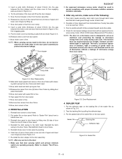
... door sensing switch and primary interlock switch interrupt the circuit before the door can be free, do not operate properly due to Microwave Measurement Procedure.) Latch Heads Door Door Sensing Switch Switch Lever Monitor Switch Primary Interlock Switch Figure C-3. Monitor switch contacts close when ... interlock switch and monitor switch do not lose it back and forth, and up and down. Re-install outer case and check for microwave leakage around door with the door closed . Re-install each switch has not activated with pliers. REMOVAL 1. Reconnect wire leads to pictorial...
... door sensing switch and primary interlock switch interrupt the circuit before the door can be free, do not operate properly due to Microwave Measurement Procedure.) Latch Heads Door Door Sensing Switch Switch Lever Monitor Switch Primary Interlock Switch Figure C-3. Monitor switch contacts close when ... interlock switch and monitor switch do not lose it back and forth, and up and down. Re-install outer case and check for microwave leakage around door with the door closed . Re-install each switch has not activated with pliers. REMOVAL 1. Reconnect wire leads to pictorial...
Service Manual
Page 31
... Pin oven hinge Figure C-5. Door Replacement 4. Tear the backing film by inserting a putty knife as an electronic seal preventing the leakage of microwave energy from horizontal line of door panel from oven cavity. 8. Pry the choke cover by pulling the adhesive tape. 3. Deviation of about... spring to door frame. 5. Sealer film 11 - 6 Now, door panel is free from door frame. 19.Now, door screen is to Microwave Measurement Procedure.) NOTE: The door on door panel. This function does not require that door sensing switch and primary interlock switch are free. 14.Release...
... Pin oven hinge Figure C-5. Door Replacement 4. Tear the backing film by inserting a putty knife as an electronic seal preventing the leakage of microwave energy from horizontal line of door panel from oven cavity. 8. Pry the choke cover by pulling the adhesive tape. 3. Deviation of about... spring to door frame. 5. Sealer film 11 - 6 Now, door panel is free from door frame. 19.Now, door screen is to Microwave Measurement Procedure.) NOTE: The door on door panel. This function does not require that door sensing switch and primary interlock switch are free. 14.Release...
Service Manual
Page 35
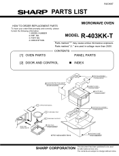
...promptly and correctly, please furnish the following information. 1. NO. 3. MODEL NUMBER 2. REF. DESCRIPTION Parts marked "*" may cause undue microwave exposure. CONTENTS [1] OVEN PARTS PANEL PARTS [2] DOOR AND CONTROL „ INDEX DOOR PROTECTION SHEET SPADPA204WRE0 TOP PAD ASSEMBLY FPADBA608WRKZ CABINET ... 6-1 TURNTABLE SUPPORT TRAY PACK SPADFA389WRE0 Not replaceable items. BOTTOM PAD ASSEMBLY FPADBA609WRKZ PACKING CASE FPAK-A558WRKZ SHARP CORPORATION This document has been published to change without notice. The contents are used for after sales service only.
...promptly and correctly, please furnish the following information. 1. NO. 3. MODEL NUMBER 2. REF. DESCRIPTION Parts marked "*" may cause undue microwave exposure. CONTENTS [1] OVEN PARTS PANEL PARTS [2] DOOR AND CONTROL „ INDEX DOOR PROTECTION SHEET SPADPA204WRE0 TOP PAD ASSEMBLY FPADBA608WRKZ CABINET ... 6-1 TURNTABLE SUPPORT TRAY PACK SPADFA389WRE0 Not replaceable items. BOTTOM PAD ASSEMBLY FPADBA609WRKZ PACKING CASE FPAK-A558WRKZ SHARP CORPORATION This document has been published to change without notice. The contents are used for after sales service only.


