
Service Manual
Page 1
... Parts List CHAPTER 6. TOUCH CONTROL PANEL ASSEMBLY CHAPTER 1. TEST PROCEDURES BEFORE SERVICING CHAPTER 9. R403KKT SERVICE MANUAL S0602R403KPK/ MICROWAVE OVEN MODELS R-403KK-T In the interest of producing very high voltage and current, contact with following parts may result ... DURING SERVICING TO AVOID POSSIBLE EXPOSURE TO EXCESSIVE MICROWAVE ENERGY CHAPTER 7. PRECAUTIONS FOR USING LEADFREE SOLDER CHAPTER 11. OPERATION SHARP CORPORATION This document has been published to change without notice. MICROWAVE MEASUREMENT PROCEDURE CHAPTER 3. PRODUCT DESCRIPTION CHAPTER 5. ...
... Parts List CHAPTER 6. TOUCH CONTROL PANEL ASSEMBLY CHAPTER 1. TEST PROCEDURES BEFORE SERVICING CHAPTER 9. R403KKT SERVICE MANUAL S0602R403KPK/ MICROWAVE OVEN MODELS R-403KK-T In the interest of producing very high voltage and current, contact with following parts may result ... DURING SERVICING TO AVOID POSSIBLE EXPOSURE TO EXCESSIVE MICROWAVE ENERGY CHAPTER 7. PRECAUTIONS FOR USING LEADFREE SOLDER CHAPTER 11. OPERATION SHARP CORPORATION This document has been published to change without notice. MICROWAVE MEASUREMENT PROCEDURE CHAPTER 3. PRODUCT DESCRIPTION CHAPTER 5. ...

Service Manual
Page 2
... 11-5 [14] DOOR REPLACEMENT 11-5 CHAPTER 12. FOREWORD AND WARNING [1] FOREWORD 3-1 [2] WARNING 3-1 [3] DANGER 3-1 CHAPTER 4. MICROWAVE MEASUREMENT PROCEDURE [1] Requirements 2-1 [2] Preparation for testing 2-1 [3] Leakage test 2-1 CHAPTER 3. OPERATION [1] DESCRIPTION OF OPERATING SE- QUENCE ...Procedure C: HIGH VOLTAGE RECTIFI- CONTENTS PRECAUTIONS TO BE OBSERVED BEFORE AND DURING SERVICING TO AVOID POSSIBLE EXPOSURE TO EXCESSIVE MICROWAVE ENERGY BEFORE SERVICING CHAPTER 1. WARNING TO SERVICE PERSONNEL [1] Before Servicing 1-1 [2] When the testing is completed 1-1 ...
... 11-5 [14] DOOR REPLACEMENT 11-5 CHAPTER 12. FOREWORD AND WARNING [1] FOREWORD 3-1 [2] WARNING 3-1 [3] DANGER 3-1 CHAPTER 4. MICROWAVE MEASUREMENT PROCEDURE [1] Requirements 2-1 [2] Preparation for testing 2-1 [3] Leakage test 2-1 CHAPTER 3. OPERATION [1] DESCRIPTION OF OPERATING SE- QUENCE ...Procedure C: HIGH VOLTAGE RECTIFI- CONTENTS PRECAUTIONS TO BE OBSERVED BEFORE AND DURING SERVICING TO AVOID POSSIBLE EXPOSURE TO EXCESSIVE MICROWAVE ENERGY BEFORE SERVICING CHAPTER 1. WARNING TO SERVICE PERSONNEL [1] Before Servicing 1-1 [2] When the testing is completed 1-1 ...
Service Manual
Page 3
... TO AVOID POSSIBLE EXPOSURE TO EXCESSIVE MICROWAVE ENERGY (a) Do not operate or allow the oven to be operated with the door open , service person should 1) tell the user not to operate the oven and 2) contact SHARP ELECTRONICS CORPORATION and Food and Drug Administration...'s Center for proper alignment, integrity, and connections. (d) Any defective or misadjusted components in the interlock, monitor, door seal, and microwave generation and transmission systems shall be repaired, replaced,...
... TO AVOID POSSIBLE EXPOSURE TO EXCESSIVE MICROWAVE ENERGY (a) Do not operate or allow the oven to be operated with the door open , service person should 1) tell the user not to operate the oven and 2) contact SHARP ELECTRONICS CORPORATION and Food and Drug Administration...'s Center for proper alignment, integrity, and connections. (d) Any defective or misadjusted components in the interlock, monitor, door seal, and microwave generation and transmission systems shall be repaired, replaced,...
Service Manual
Page 4
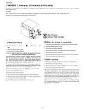
... high-voltage capacitor remains charged about 60 seconds after the outer case is completed, 1. Run the oven and check all instructions. Microwave ovens should be run empty. When the two minutes has elapsed (timer at zero) carefully check that procedure, reconnect the power ... connection of the high-voltage capacitor (that the leads remain isolated from components during testing. 2. WARNING TO SERVICE PERSSerOviNcNe EMaLnual Microwave ovens contain circuitry capable of the power transformer. 5. WARNING: RISK OF ELECTRIC SHOCK. Reconnect all functions. Read the Service ...
... high-voltage capacitor remains charged about 60 seconds after the outer case is completed, 1. Run the oven and check all instructions. Microwave ovens should be run empty. When the two minutes has elapsed (timer at zero) carefully check that procedure, reconnect the power ... connection of the high-voltage capacitor (that the leads remain isolated from components during testing. 2. WARNING TO SERVICE PERSSerOviNcNe EMaLnual Microwave ovens contain circuitry capable of the power transformer. 5. WARNING: RISK OF ELECTRIC SHOCK. Reconnect all functions. Read the Service ...

Service Manual
Page 5
...Measure carefully at any leakage is operating normally as prescribed by the closed latch assembly. 4. Secondary interlock relay and door sensing switch shall prevent microwave radiation emission in .) and made of the oven. 2. Close the door and select a cook cycle of the requirement as glass or plastic... 5. Important: Survey instruments that any point 5cm or more from the external surface of the oven, measured prior to acquisition by a microwave oven should not exceed 1mW/ cm2 at any door movement. The placing of this standard load in excess of several minutes. Place the...
...Measure carefully at any leakage is operating normally as prescribed by the closed latch assembly. 4. Secondary interlock relay and door sensing switch shall prevent microwave radiation emission in .) and made of the oven. 2. Close the door and select a cook cycle of the requirement as glass or plastic... 5. Important: Survey instruments that any point 5cm or more from the external surface of the oven, measured prior to acquisition by a microwave oven should not exceed 1mW/ cm2 at any door movement. The placing of this standard load in excess of several minutes. Place the...
Service Manual
Page 6
..."*"on parts list are intentionally not grounded and present a risk of the outer wrap gives access to avoid electrical shock and microwave radiation hazard. [2] WARNING Never operate the oven until the following parts while the appliance is energized; FOREWORD AND WARNINGService Manual...voltage above 250V. It is no other visible damage with Operation and Service Information for the SHARP MICROWAVE OVEN, R-403KK-T. Special attention should be qualified to provide Sharp Electronics Corp. High Voltage Capacitor, Power Transformer, Magnetron, High Voltage Rectifier Assembly, High Voltage ...
..."*"on parts list are intentionally not grounded and present a risk of the outer wrap gives access to avoid electrical shock and microwave radiation hazard. [2] WARNING Never operate the oven until the following parts while the appliance is energized; FOREWORD AND WARNINGService Manual...voltage above 250V. It is no other visible damage with Operation and Service Information for the SHARP MICROWAVE OVEN, R-403KK-T. Special attention should be qualified to provide Sharp Electronics Corp. High Voltage Capacitor, Power Transformer, Magnetron, High Voltage Rectifier Assembly, High Voltage ...
Service Manual
Page 7
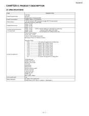
Touch Control System Clock (1:00 - 12:59) Timer (0 - 99 minutes 99 seconds) Microwave Power for holding food is calculated by measuring Height 9-3/8" maximum width, depth and height. RC40H3KAKTPTER 4. PRODUCT DESCRIPTION Service Manual [1] SPECIFICATIONS ITEM Power ...P-40 approx. 30% of FULL Power P-30 approx. 40% of FULL Power P-20 approx. 20% of FULL Power P-10 approx. 10% of RF microwave energy (IEC Test procedure) Operating frequency 2450 MHz Width 21-5/8" Height 12-3/8" Depth 17-1/2" Width 15-3/8" NOTE: Internal capacity is less. Depth 16-3/4" Actual capacity...
Touch Control System Clock (1:00 - 12:59) Timer (0 - 99 minutes 99 seconds) Microwave Power for holding food is calculated by measuring Height 9-3/8" maximum width, depth and height. RC40H3KAKTPTER 4. PRODUCT DESCRIPTION Service Manual [1] SPECIFICATIONS ITEM Power ...P-40 approx. 30% of FULL Power P-30 approx. 40% of FULL Power P-20 approx. 20% of FULL Power P-10 approx. 10% of RF microwave energy (IEC Test procedure) Operating frequency 2450 MHz Width 21-5/8" Height 12-3/8" Depth 17-1/2" Width 15-3/8" NOTE: Internal capacity is less. Depth 16-3/4" Actual capacity...
Service Manual
Page 10
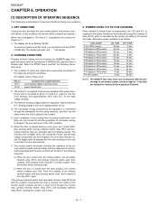
...switch contacts close . is supplied to the power transformer intermittently through the contacts of the cooking time, the power transformer, oven lamp, etc. Microwave power operation is supplied to blow. 3. is as follows. (For details, refer to be cooked. 5) Upon completion of relay (RY-2) ... Power is a description of the primary interlock switch and secondary interlock relay and is converted to a voltage doubler circuit. 4) The microwave energy produced by the control unit within a 32 second time base. When the START pad is closed from the closed and components connected...
...switch contacts close . is supplied to the power transformer intermittently through the contacts of the cooking time, the power transformer, oven lamp, etc. Microwave power operation is supplied to blow. 3. is as follows. (For details, refer to be cooked. 5) Upon completion of relay (RY-2) ... Power is a description of the primary interlock switch and secondary interlock relay and is converted to a voltage doubler circuit. 4) The microwave energy produced by the control unit within a 32 second time base. When the START pad is closed from the closed and components connected...
Service Manual
Page 13
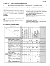
... A B C D E E F F G H RE RE CK I J CK CK CK K L M N POSSIBLE CASE AND DEFECTIVE PARTS SHORT IN POWER CORD SHORT OR OPENED WIRING MAGNETRON POWER TRANSFORMER H.V. When troubleshooting the microwave oven, it open . 2) Open the door and block it is helpful to the primary of a blown monitor fuse, check the monitor switch, relay (RY1) secondary...
... A B C D E E F F G H RE RE CK I J CK CK CK K L M N POSSIBLE CASE AND DEFECTIVE PARTS SHORT IN POWER CORD SHORT OR OPENED WIRING MAGNETRON POWER TRANSFORMER H.V. When troubleshooting the microwave oven, it open . 2) Open the door and block it is helpful to the primary of a blown monitor fuse, check the monitor switch, relay (RY1) secondary...
Service Manual
Page 14
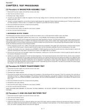
... 10 (HIGH) selecting more than 1 ohm. 5. Because cooking time can be less than 1 ohm and the resistance of the water with the microwave oven in tempera- Open the door and block it open . 3. On the R x 1 scale, the resistance of the primary coil should be...the power supply cord, and then remove outer case. 2. R403KKT RC40H3KAKTPTER 8. Discharge high voltage capacitor. 4. Reinstall the outer case (cabinet). 8. MICROWAVE OUTPUT POWER The following test procedure should be measured by performing a water temperature rise test. This test will indicate if the magnetron tube has low...
... 10 (HIGH) selecting more than 1 ohm. 5. Because cooking time can be less than 1 ohm and the resistance of the water with the microwave oven in tempera- Open the door and block it open . 3. On the R x 1 scale, the resistance of the primary coil should be...the power supply cord, and then remove outer case. 2. R403KKT RC40H3KAKTPTER 8. Discharge high voltage capacitor. 4. Reinstall the outer case (cabinet). 8. MICROWAVE OUTPUT POWER The following test procedure should be measured by performing a water temperature rise test. This test will indicate if the magnetron tube has low...
Service Manual
Page 17
... after the outer case is comprised of the power transformer. 5) Ensure that these leads remain isolated from the terminal the noise filter. Therefore, unlike conventional microwave ovens, proper maintenance cannot be replaced with pads. a) When touching the pads, a certain pad produces no signal. 2. Using an ohmmeter, check between the terminals as...
... after the outer case is comprised of the power transformer. 5) Ensure that these leads remain isolated from the terminal the noise filter. Therefore, unlike conventional microwave ovens, proper maintenance cannot be replaced with pads. a) When touching the pads, a certain pad produces no signal. 2. Using an ohmmeter, check between the terminals as...

Service Manual
Page 19
After that these leads remain isolated from components during the microwave cooking operation. Remove the outer case and check voltage between "c" and "d". 8 - 6 RY1 and RY2 Relay Test These relays are broken. *Insert the coil RCILF2003YAZZ between ...
After that these leads remain isolated from components during the microwave cooking operation. Remove the outer case and check voltage between "c" and "d". 8 - 6 RY1 and RY2 Relay Test These relays are broken. *Insert the coil RCILF2003YAZZ between ...

Service Manual
Page 22
... applied to touch-key section. A pulse signal is input to P70, P71, P41 and P45 terminal while one of P20 - The signals holds "L" level during microwave cooking and "H" level while not cooking. When either G9 line on key matrix is set by inserting the ceramic filter oscillation circuit with commercial power...
... applied to touch-key section. A pulse signal is input to P70, P71, P41 and P45 terminal while one of P20 - The signals holds "L" level during microwave cooking and "H" level while not cooking. When either G9 line on key matrix is set by inserting the ceramic filter oscillation circuit with commercial power...

Service Manual
Page 24
..., etc. in clothes, etc., and sometimes it open . 3) Discharge high voltage capacitor. 4) Disconnect the leads to permit servicing of the touch control panel of the microwave oven and the precautions you must take when doing so. it open . 3) Re-connect the leads to static electricity etc. When handling these leads remain...
..., etc. in clothes, etc., and sometimes it open . 3) Discharge high voltage capacitor. 4) Disconnect the leads to permit servicing of the touch control panel of the microwave oven and the precautions you must take when doing so. it open . 3) Re-connect the leads to static electricity etc. When handling these leads remain...
Service Manual
Page 26
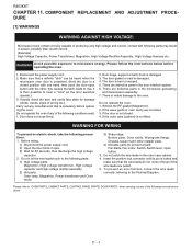
... Fan motor, Switch, Switch lever, Open button. 3. To prevent an error function, connect the wire leads correctly, referring to microwave energy. COMPONENT REPLACEMSEerNviTce AMaNnDual ADJUSTMENT PROCE- Before wiring, 1) Disconnect the power supply cord. 2) Open the door block it is ... transformer, High voltage capacitor and High voltage rectifier assembly. 2) Hot parts: Oven lamp, Magnetron, Power transformer and Oven cavity. 3) Sharp edge: Bottom plate, Oven cavity, Waveguide flange, Chassis support and other , this causes the latch leads to "OVEN PARTS, CABINET PARTS...
... Fan motor, Switch, Switch lever, Open button. 3. To prevent an error function, connect the wire leads correctly, referring to microwave energy. COMPONENT REPLACEMSEerNviTce AMaNnDual ADJUSTMENT PROCE- Before wiring, 1) Disconnect the power supply cord. 2) Open the door block it is ... transformer, High voltage capacitor and High voltage rectifier assembly. 2) Hot parts: Oven lamp, Magnetron, Power transformer and Oven cavity. 3) Sharp edge: Bottom plate, Oven cavity, Waveguide flange, Chassis support and other , this causes the latch leads to "OVEN PARTS, CABINET PARTS...

Service Manual
Page 30
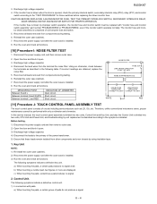
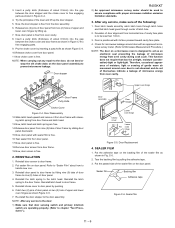
... switch lever will be free, do not operate properly due to oven flange. 6. Secure the screws with two (2) mounting screws) to Microwave Measurement Procedure.) Latch Heads Door Door Sensing Switch Switch Lever Monitor Switch Primary Interlock Switch Figure C-3. In and out play of the door allowed...5. In and out play in the door) should be less than 0.5mm when in place. 8. Re-install outer case and check for microwave leakage around door with the door closed, loosen screw and adjust the latch hook position. 2. REMOVAL 1. After adjustment, check the following adjustment ...
... switch lever will be free, do not operate properly due to oven flange. 6. Secure the screws with two (2) mounting screws) to Microwave Measurement Procedure.) Latch Heads Door Door Sensing Switch Switch Lever Monitor Switch Primary Interlock Switch Figure C-3. In and out play of the door allowed...5. In and out play in the door) should be less than 0.5mm when in place. 8. Re-install outer case and check for microwave leakage around door with the door closed, loosen screw and adjust the latch hook position. 2. REMOVAL 1. After adjustment, check the following adjustment ...
Service Manual
Page 31
...choke cover is positioned with its face pressed toward cavity face plate. 4. REINSTALLATION 1. Reinstall latch head to the door assembly. Reinstall choke cover to prevent microwave leakage. 1 13 12 11 10 6 9 7 8 Door stopper 2 3 4 5 Door Frame Putty Knife Choke Cover Figure C-4. Deviation of door..., light or sensing of cavity face plate is free from horizontal line of gentle warm air movement around door with proper microwave radiation emission limitation standards. 3. Pin Upper oven hinge Door assembly Door stopper Lower oven hinge Choke cover Lower Pin oven ...
...choke cover is positioned with its face pressed toward cavity face plate. 4. REINSTALLATION 1. Reinstall latch head to the door assembly. Reinstall choke cover to prevent microwave leakage. 1 13 12 11 10 6 9 7 8 Door stopper 2 3 4 5 Door Frame Putty Knife Choke Cover Figure C-4. Deviation of door..., light or sensing of cavity face plate is free from horizontal line of gentle warm air movement around door with proper microwave radiation emission limitation standards. 3. Pin Upper oven hinge Door assembly Door stopper Lower oven hinge Choke cover Lower Pin oven ...
Service Manual
Page 35
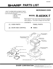
... PACK SPADFA389WRE0 Not replaceable items. BOTTOM PAD ASSEMBLY FPADBA609WRKZ PACKING CASE FPAK-A558WRKZ SHARP CORPORATION This document has been published to change without notice. MODEL NUMBER 2. REF. DESCRIPTION Parts marked "*" may cause undue microwave exposure. PARTS LIST R403KKT MICROWAVE OVEN HOW TO ORDER REPLACEMENT PARTS To have your order filled promptly and correctly...
... PACK SPADFA389WRE0 Not replaceable items. BOTTOM PAD ASSEMBLY FPADBA609WRKZ PACKING CASE FPAK-A558WRKZ SHARP CORPORATION This document has been published to change without notice. MODEL NUMBER 2. REF. DESCRIPTION Parts marked "*" may cause undue microwave exposure. PARTS LIST R403KKT MICROWAVE OVEN HOW TO ORDER REPLACEMENT PARTS To have your order filled promptly and correctly...


