
Service Manual
Page 1
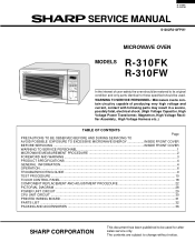
... MANUAL S1202R310FPW/ MICROWAVE OVEN MODELS R-310FK R-310FW REHEAT CENTER COMPU DEFROST In the interest of producing very high voltage and current, contact with following parts may result in a severe, possibly fatal, electrical shock. (High Voltage Capacitor, High Voltage Power Transformer, Magnetron, High ... PROCEDURE 22 PICTORIAL DIAGRAM ...28 POWER UNIT CIRCUIT ...29 CPU UNIT CIRCUIT ...30 PRINTED WIRING BOARD ...31 PARTS LIST ...32 PACKING AND ACCESSORIES ...36 SHARP CORPORATION This document has been published to be used for after sales service only. The contents are subject to...
... MANUAL S1202R310FPW/ MICROWAVE OVEN MODELS R-310FK R-310FW REHEAT CENTER COMPU DEFROST In the interest of producing very high voltage and current, contact with following parts may result in a severe, possibly fatal, electrical shock. (High Voltage Capacitor, High Voltage Power Transformer, Magnetron, High ... PROCEDURE 22 PICTORIAL DIAGRAM ...28 POWER UNIT CIRCUIT ...29 CPU UNIT CIRCUIT ...30 PRINTED WIRING BOARD ...31 PARTS LIST ...32 PACKING AND ACCESSORIES ...36 SHARP CORPORATION This document has been published to be used for after sales service only. The contents are subject to...
Service Manual
Page 3
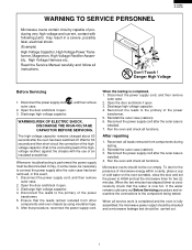
... carry out Before Servicing procedure and reexamine the connections to the primary of the power transformer. 5. R - 3 10 F K R-310FW WARNING TO SERVICE PERSONNEL Microwave ovens contain circuitry capable of producing very high voltage and current, contact with the use of an insulated screwdriver... . 3. Whenever troubleshooting is installed. 7. When the testing is the connecting lead of the highvoltage rectifier) against the chassis with following parts may , in this event, 1. Discharge high voltage capacitor. 4. Reconnect all service work is completed and the oven is fully assembled,...
... carry out Before Servicing procedure and reexamine the connections to the primary of the power transformer. 5. R - 3 10 F K R-310FW WARNING TO SERVICE PERSONNEL Microwave ovens contain circuitry capable of producing very high voltage and current, contact with the use of an insulated screwdriver... . 3. Whenever troubleshooting is installed. 7. When the testing is the connecting lead of the highvoltage rectifier) against the chassis with following parts may , in this event, 1. Discharge high voltage capacitor. 4. Reconnect all service work is completed and the oven is fully assembled,...
Service Manual
Page 5
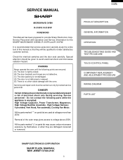
... damaged, loosened or removed. It is no other visible damage with Operation and Service Information for the SHARP MICROWAVE OVENS, R-310FK and R-310FW. DANGER Certain initial parts are not defective. (C) The door packing is not damaged. (D) The door is not deformed or ... AND ADJUSTMENT PROCEDURE WIRING DIAGRAM PARTS LIST SHARP ELECTRONICS CORPORATION SHARP PLAZA, MAHWAH, NEW JERSEY 07430-2135 3 SERVICE MANUAL MICROWAVE OVEN R-310FK/ R-310FW FOREWORD This Manual has been prepared to voltage above 250V. All the parts marked "*" on parts list may cause undue microwave ...
... damaged, loosened or removed. It is no other visible damage with Operation and Service Information for the SHARP MICROWAVE OVENS, R-310FK and R-310FW. DANGER Certain initial parts are not defective. (C) The door packing is not damaged. (D) The door is not deformed or ... AND ADJUSTMENT PROCEDURE WIRING DIAGRAM PARTS LIST SHARP ELECTRONICS CORPORATION SHARP PLAZA, MAHWAH, NEW JERSEY 07430-2135 3 SERVICE MANUAL MICROWAVE OVEN R-310FK/ R-310FW FOREWORD This Manual has been prepared to voltage above 250V. All the parts marked "*" on parts list may cause undue microwave ...
Service Manual
Page 11
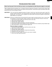
... fuse is performed with your hand or an uninsulated tool while the power supply is installed. 7. Use part FFSBA021WRK0 as an assembly. Open the door and block it open . 3. R - 3 10 F K R-310FW TROUBLESHOOTING GUIDE Never touch any part in the circuit with the power supply cord disconnected. Reconnect all functions. 9 These tests are given...
... fuse is performed with your hand or an uninsulated tool while the power supply is installed. 7. Use part FFSBA021WRK0 as an assembly. Open the door and block it open . 3. R - 3 10 F K R-310FW TROUBLESHOOTING GUIDE Never touch any part in the circuit with the power supply cord disconnected. Reconnect all functions. 9 These tests are given...
Service Manual
Page 12
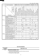
... PROBLEM Home fuse or circuit breaker blows when power cord is plugged into wall outlet. R-310FK R-310FW TEST PROCEDURE CK = Check / RE = Replace RE RE A B C D E F F G H RE RE CK I CK CK CK J K L M POSSIBLE CAUSE AND DEFECTIVE PARTS SHORT IN POWER CORD SHORT OR OPENED WIRING MAGNETRON POWER TRANSFORMER H.V. Display does not operate properly...
... PROBLEM Home fuse or circuit breaker blows when power cord is plugged into wall outlet. R-310FK R-310FW TEST PROCEDURE CK = Check / RE = Replace RE RE A B C D E F F G H RE RE CK I CK CK CK J K L M POSSIBLE CAUSE AND DEFECTIVE PARTS SHORT IN POWER CORD SHORT OR OPENED WIRING MAGNETRON POWER TRANSFORMER H.V. Display does not operate properly...
Service Manual
Page 16
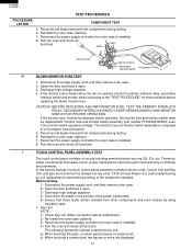
...blown by improper switch operation, the monitor fuse and monitor switch must be performed with "monitor fuse and monitor switch assembly" part number FFS-BA021WRK0, even if the monitor switch operates normally. NOTE ; 1) Check Key unit ribbon connection before replacing the... monitor switch according to the symptoms indicated. b) When touching a number pad, two figures or more are displayed. 14 R-310FK R-310FW TEST PROCEDURES PROCEDURE LETTER COMPONENT TEST 5. RED WHT Screw Driver Monitor Switch Secondary Interlock Switch Ohmmeter H BLOWN MONITOR FUSE TEST 1. Therefore...
...blown by improper switch operation, the monitor fuse and monitor switch must be performed with "monitor fuse and monitor switch assembly" part number FFS-BA021WRK0, even if the monitor switch operates normally. NOTE ; 1) Check Key unit ribbon connection before replacing the... monitor switch according to the symptoms indicated. b) When touching a number pad, two figures or more are displayed. 14 R-310FK R-310FW TEST PROCEDURES PROCEDURE LETTER COMPONENT TEST 5. RED WHT Screw Driver Monitor Switch Secondary Interlock Switch Ohmmeter H BLOWN MONITOR FUSE TEST 1. Therefore...
Service Manual
Page 19
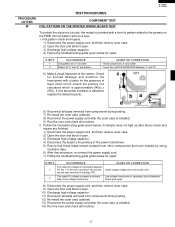
... to the primary on the PWB, this model is approximately 540Ω ± 20%). Pattern at "a" is detected, replace the defective parts. Low voltage transformer or secondary circuit defective. R - 3 10 F K R-310FW TEST PROCEDURES PROCEDURE LETTER COMPONENT TEST M FOIL PATTERN ON THE PRINTED WIRING BOARD TEST To protect the electronic circuits, this foil...
... to the primary on the PWB, this model is approximately 540Ω ± 20%). Pattern at "a" is detected, replace the defective parts. Low voltage transformer or secondary circuit defective. R - 3 10 F K R-310FW TEST PROCEDURES PROCEDURE LETTER COMPONENT TEST M FOIL PATTERN ON THE PRINTED WIRING BOARD TEST To protect the electronic circuits, this foil...
Service Manual
Page 23
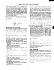
...preventing static electricity. 2) Connect the connectors of the circuits. Servicing Tools Tools required to the control unit being closed . B. in the integral part of the key unit to service the touch control panel assembly. 1) Soldering iron: 30W (It is available either from the oven proper, ...ends of the door sensing switch (on PWB) of the touch control panel by using the dummy resistor(s). 3. R - 3 10 F K R-310FW TOUCH CONTROL PANEL SERVICING 1. Other Precautions 1) Before turning on the power source of the control unit, remove the aluminium foil applied for the sensor-...
...preventing static electricity. 2) Connect the connectors of the circuits. Servicing Tools Tools required to the control unit being closed . B. in the integral part of the key unit to service the touch control panel assembly. 1) Soldering iron: 30W (It is available either from the oven proper, ...ends of the door sensing switch (on PWB) of the touch control panel by using the dummy resistor(s). 3. R - 3 10 F K R-310FW TOUCH CONTROL PANEL SERVICING 1. Other Precautions 1) Before turning on the power source of the control unit, remove the aluminium foil applied for the sensor-...
Service Manual
Page 24
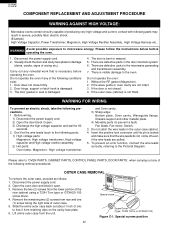
... To prevent an electric shock, take the following parts; 1) High voltage parts: Magnetron, High voltage transformer, High voltage capacitor and High voltage rectifier assembly. 2) Hot parts: Oven lamp, Magnetron, High voltage transformer and Oven cavity. 3) Sharp edge: Bottom plate, Oven cavity, Waveguide flange,... the right side of the rear cabinet using a T20H Torx type or GTXH20-100 screw driver. 4. R-310FK R-310FW COMPONENT REPLACEMENT AND ADJUSTMENT PROCEDURE WARNING AGAINST HIGH VOLTAGE: Microwave ovens contain circuitry capable of producing very high voltage and current,...
... To prevent an electric shock, take the following parts; 1) High voltage parts: Magnetron, High voltage transformer, High voltage capacitor and High voltage rectifier assembly. 2) Hot parts: Oven lamp, Magnetron, High voltage transformer and Oven cavity. 3) Sharp edge: Bottom plate, Oven cavity, Waveguide flange,... the right side of the rear cabinet using a T20H Torx type or GTXH20-100 screw driver. 4. R-310FK R-310FW COMPONENT REPLACEMENT AND ADJUSTMENT PROCEDURE WARNING AGAINST HIGH VOLTAGE: Microwave ovens contain circuitry capable of producing very high voltage and current,...

Service Manual
Page 28
R-310FK R-310FW If the door sensing switch, secondary interlock switch and monitor switch do not bend or warp the slit choke (tabs on the door panel assembly) ... oven face. Release two (2) pins of door panel from two (2) holes of door frame. 11.Now, door panel with door frame is to free engaging parts. 4. Remove the four (4) screws holding latch hook to the door frame. 10.Release door panel from oven cavity. After any repair to the door, do...
R-310FK R-310FW If the door sensing switch, secondary interlock switch and monitor switch do not bend or warp the slit choke (tabs on the door panel assembly) ... oven face. Release two (2) pins of door panel from two (2) holes of door frame. 11.Now, door panel with door frame is to free engaging parts. 4. Remove the four (4) screws holding latch hook to the door frame. 10.Release door panel from oven cavity. After any repair to the door, do...
Service Manual
Page 34
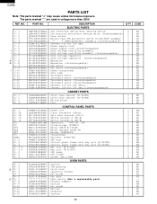
... Oven lamp Turntable motor Turntable motor (Interchangeable) Turntable motor (Interchangeable) Turntable motor (Interchangeable) Thermal cut-out 145 deg.C Thermal cut -out 125 deg. REF. R-310FK R-310FW PARTS LIST Note: The parts marked "∆" may cause undue microwave exposure. NO. 1- 1 1- 1 1- 2 1- 3 1- 3 1- 4 1- 5 1- 5 * 1- 6 * 1- 6 * 1- 7 * 1- 7 ∆* 1- 8 ∆* 1- 8 1- 9 1- 9 * 1-10 1-11 1-12 1-12 1-12 1-12 1-13 1-13...
... Oven lamp Turntable motor Turntable motor (Interchangeable) Turntable motor (Interchangeable) Turntable motor (Interchangeable) Thermal cut-out 145 deg.C Thermal cut -out 125 deg. REF. R-310FK R-310FW PARTS LIST Note: The parts marked "∆" may cause undue microwave exposure. NO. 1- 1 1- 1 1- 2 1- 3 1- 3 1- 4 1- 5 1- 5 * 1- 6 * 1- 6 * 1- 7 * 1- 7 ∆* 1- 8 ∆* 1- 8 1- 9 1- 9 * 1-10 1-11 1-12 1-12 1-12 1-12 1-13 1-13...
Service Manual
Page 35
...2. REF. REF. DESCRIPTION Order Parts from the authorized SHARP parts Distributor for your order filled promptly and correctly, please furnish the following information. 1. Defective parts requiring return should be returned as indicated in the Service Policy. 33 PART NO. 4. PCOVPA349WRE0 PCUSGA339WRP0 PCUSGA399WRE0 ...DESCRIPTION Waveguide cover Cushion Cushion Cushion Cushion Cushion Cushion Cushion Cushion DOOR PARTS Door panel Sealer film Door frame [R-310FK] Door frame [R-310FW] Door screen [R-310FK] Door screen [R-310FW] Latch head Latch spring Screw : 4mm x 8mm Cushion Cushion ...
...2. REF. REF. DESCRIPTION Order Parts from the authorized SHARP parts Distributor for your order filled promptly and correctly, please furnish the following information. 1. Defective parts requiring return should be returned as indicated in the Service Policy. 33 PART NO. 4. PCOVPA349WRE0 PCUSGA339WRP0 PCUSGA399WRE0 ...DESCRIPTION Waveguide cover Cushion Cushion Cushion Cushion Cushion Cushion Cushion Cushion DOOR PARTS Door panel Sealer film Door frame [R-310FK] Door frame [R-310FW] Door screen [R-310FK] Door screen [R-310FW] Latch head Latch spring Screw : 4mm x 8mm Cushion Cushion ...

Service Manual
Page 36
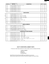
R-310FK R-310FW 1 2 3 4 OVEN AND CABINET PARTS 2-1 A 4-22 5 7-6 7-8 6 A 7-6 4-9 B 4-17 7-10 B 7-8 4-20 1-4 6-7 7-6 4-13 1-8 7-7 C 4-11 4-7 6-6 C 7-6 D 4-12 E 4-14 6-2 F 6-1 G 4-2 1-12 7-1 4-1 4-10 7-3 4-21 7-6 1-5 D 7-4 4-15 7-9 7-1 4-21 1-6 1-1 4-19 1-7 4-22 7-2 1-13 7-6 E 4-4 7-6 4-8 4-18 1-3 1-2 4-5 1-10 4-3 1-1 7-5 7-1 2-2 7-6 7-3 F 4-6 4-16 1-11 1-9 7-1 G 7-6 7-6 H 7-6 2-3 7-6 1 2 3 4 5 34 H 6
R-310FK R-310FW 1 2 3 4 OVEN AND CABINET PARTS 2-1 A 4-22 5 7-6 7-8 6 A 7-6 4-9 B 4-17 7-10 B 7-8 4-20 1-4 6-7 7-6 4-13 1-8 7-7 C 4-11 4-7 6-6 C 7-6 D 4-12 E 4-14 6-2 F 6-1 G 4-2 1-12 7-1 4-1 4-10 7-3 4-21 7-6 1-5 D 7-4 4-15 7-9 7-1 4-21 1-6 1-1 4-19 1-7 4-22 7-2 1-13 7-6 E 4-4 7-6 4-8 4-18 1-3 1-2 4-5 1-10 4-3 1-1 7-5 7-1 2-2 7-6 7-3 F 4-6 4-16 1-11 1-9 7-1 G 7-6 7-6 H 7-6 2-3 7-6 1 2 3 4 5 34 H 6

Service Manual
Page 37
1 2 CONTROL PANEL PARTS A 3-3 3-4 B 3-3-1 C 3 3-2 3-6 3-5 4 5 3-6 3-1 DOOR PARTS 5-11 5-7 R - 3 10 F K R-310FW 6 A B C D E 5-3 F 5-4 5-1 5-10 5-9 5-2 5-7 D 5-7 5-7 E 5-7 5-10 5-9 5-5 F 5-6 G H 1 5-8 6-3 2 MISCELLANEOUS 6-5 Actual wire harness may be different from illustration. 3 4 5 35 G H 6
1 2 CONTROL PANEL PARTS A 3-3 3-4 B 3-3-1 C 3 3-2 3-6 3-5 4 5 3-6 3-1 DOOR PARTS 5-11 5-7 R - 3 10 F K R-310FW 6 A B C D E 5-3 F 5-4 5-1 5-10 5-9 5-2 5-7 D 5-7 5-7 E 5-7 5-10 5-9 5-5 F 5-6 G H 1 5-8 6-3 2 MISCELLANEOUS 6-5 Actual wire harness may be different from illustration. 3 4 5 35 G H 6

Service Manual
Page 40
No part of this publication may be reproduced, stored in retrieval systems, or transmitted in any form or by any means, electronic, mechanical, photocopying, recording, or otherwise, without prior written permission of the publisher. 2002 SHARP CORP. (1S1.700E) Printed in U.S.A 38 R-310FK R-310FW COPYRIGHT © 2002 BY SHARP CORPORATION ALL RIGHTS RESERVED.
No part of this publication may be reproduced, stored in retrieval systems, or transmitted in any form or by any means, electronic, mechanical, photocopying, recording, or otherwise, without prior written permission of the publisher. 2002 SHARP CORP. (1S1.700E) Printed in U.S.A 38 R-310FK R-310FW COPYRIGHT © 2002 BY SHARP CORPORATION ALL RIGHTS RESERVED.


