
Service Manual
Page 1
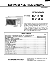
... TO AVOID POSSIBLE EXPOSURE TO EXCESSIVE MICROWAVE ENERGY INSIDE FRONT COVER BEFORE SERVICING ...INSIDE FRONT COVER WARNING TO SERVICE PERSONNEL ...1 MICROWAVE MEASUREMENT PROCEDURE 2 FOREWORD AND WARNING ...3 PRODUCT SPECIFICATIONS ...4 GENERAL INFORMATION ...4 OPERATION ...6 TROUBLESHOOTING GUIDE ...9 TEST PROCEDURE ...10 TOUCH CONTROL PANEL ...18 COMPONENT REPLACEMENT AND ADJUSTMENT PROCEDURE 22 PICTORIAL DIAGRAM ...28 POWER UNIT CIRCUIT ...29 CPU UNIT CIRCUIT ...30 PRINTED WIRING BOARD ...31 PARTS LIST ...32 PACKING AND ACCESSORIES ...36 SHARP CORPORATION This document has been...
... TO AVOID POSSIBLE EXPOSURE TO EXCESSIVE MICROWAVE ENERGY INSIDE FRONT COVER BEFORE SERVICING ...INSIDE FRONT COVER WARNING TO SERVICE PERSONNEL ...1 MICROWAVE MEASUREMENT PROCEDURE 2 FOREWORD AND WARNING ...3 PRODUCT SPECIFICATIONS ...4 GENERAL INFORMATION ...4 OPERATION ...6 TROUBLESHOOTING GUIDE ...9 TEST PROCEDURE ...10 TOUCH CONTROL PANEL ...18 COMPONENT REPLACEMENT AND ADJUSTMENT PROCEDURE 22 PICTORIAL DIAGRAM ...28 POWER UNIT CIRCUIT ...29 CPU UNIT CIRCUIT ...30 PRINTED WIRING BOARD ...31 PARTS LIST ...32 PACKING AND ACCESSORIES ...36 SHARP CORPORATION This document has been...
Service Manual
Page 2
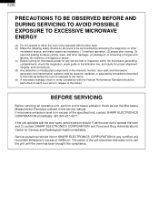
... limit, contact SHARP ELECTRONICS CORPORATION immediately @1-800-237-4277. R-310FK R-310FW PRECAUTIONS TO BE OBSERVED BEFORE AND DURING SERVICING TO AVOID POSSIBLE EXPOSURE TO EXCESSIVE MICROWAVE ENERGY (a) Do not operate or allow the oven to be operated with the door open , service person should be performed on microwave power for any service test or inspection within the microwave generating compartments, check the magnetron, wave guide or transmission...
... limit, contact SHARP ELECTRONICS CORPORATION immediately @1-800-237-4277. R-310FK R-310FW PRECAUTIONS TO BE OBSERVED BEFORE AND DURING SERVICING TO AVOID POSSIBLE EXPOSURE TO EXCESSIVE MICROWAVE ENERGY (a) Do not operate or allow the oven to be operated with the door open , service person should be performed on microwave power for any service test or inspection within the microwave generating compartments, check the magnetron, wave guide or transmission...
Service Manual
Page 3
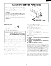
..... Ensure that is installed. 4. When all functions. Open the door and block it open . 3. Reconnect the leads to connect the power supply after the outer case is now hot. Run the oven and check all instructions. Open the door and block it open . 3. Reinstall the outer case (cabinet). 3. Reconnect the power supply cord after the oven has been switched off. Read the Service Manual carefully and follow all functions...
..... Ensure that is installed. 4. When all functions. Open the door and block it open . 3. Reconnect the leads to connect the power supply after the outer case is now hot. Run the oven and check all instructions. Open the door and block it open . 3. Reinstall the outer case (cabinet). 3. Reconnect the power supply cord after the oven has been switched off. Read the Service Manual carefully and follow all functions...
Service Manual
Page 4
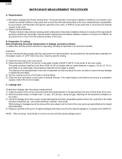
... with the requirement for instrumentation as above mentioned, secondary interlock switch shall prevent microwave radiation emission in its instruction booklet. B. R-310FK R-310FW MICROWAVE MEASUREMENT PROCEDURE A. NOTE: After servicing, record data on Full Power Cooking Mode. 5) Close the door and select a cook cycle of cool water. Preparation for leakage around the switches, indicator, and vents). The placing of this standard load in .) and made...
... with the requirement for instrumentation as above mentioned, secondary interlock switch shall prevent microwave radiation emission in its instruction booklet. B. R-310FK R-310FW MICROWAVE MEASUREMENT PROCEDURE A. NOTE: After servicing, record data on Full Power Cooking Mode. 5) Close the door and select a cook cycle of cool water. Preparation for leakage around the switches, indicator, and vents). The placing of this standard load in .) and made...
Service Manual
Page 5
... Vent Hood, Fan assembly, Cooling Fan Motor. All the parts marked "∆" on parts list are intentionally not grounded and present a risk of this manual so that service personnel carefully study the entire text of electrical shock only during servicing. Service Personnel with the oven. Special attention should be qualified to provide Sharp Electronics Corp. Service personnel - R - 3 10 F K R-310FW PRODUCT DESCRIPTION GENERAL INFORMATION OPERATION TROUBLESHOOTING GUIDE AND TEST PROCEDURE TOUCH CONTROL PANEL COMPONENT REPLACEMENT AND ADJUSTMENT PROCEDURE WIRING DIAGRAM PARTS LIST...
... Vent Hood, Fan assembly, Cooling Fan Motor. All the parts marked "∆" on parts list are intentionally not grounded and present a risk of this manual so that service personnel carefully study the entire text of electrical shock only during servicing. Service Personnel with the oven. Special attention should be qualified to provide Sharp Electronics Corp. Service personnel - R - 3 10 F K R-310FW PRODUCT DESCRIPTION GENERAL INFORMATION OPERATION TROUBLESHOOTING GUIDE AND TEST PROCEDURE TOUCH CONTROL PANEL COMPONENT REPLACEMENT AND ADJUSTMENT PROCEDURE WIRING DIAGRAM PARTS LIST...

Service Manual
Page 6
... R-310FW ITEM Power Requirements Power Output Case Dimensions Cooking Cavity Dimensions 1.2 Cubic Feet Control Complement Oven Cavity Light Safety Standard SPECIFICATION DESCRIPTION 120 Volts / 14.2 Amperes 60 Hertz Single phase, 3 wire grounded 1200 watts (IEC TEST PROCEDURE) Operating frequency of Full Power P-0 No power throughout the cooking time POPCORN pad, KEEP WARM pad, MINUTE PLUS pad INSTANT ACTION pads, REHEAT CENTER pad COMPU DEFROST pads, Number selection pads POWER LEVEL pad, TIMER/CLOCK pad STOP/CLEAR pad, START...
... R-310FW ITEM Power Requirements Power Output Case Dimensions Cooking Cavity Dimensions 1.2 Cubic Feet Control Complement Oven Cavity Light Safety Standard SPECIFICATION DESCRIPTION 120 Volts / 14.2 Amperes 60 Hertz Single phase, 3 wire grounded 1200 watts (IEC TEST PROCEDURE) Operating frequency of Full Power P-0 No power throughout the cooking time POPCORN pad, KEEP WARM pad, MINUTE PLUS pad INSTANT ACTION pads, REHEAT CENTER pad COMPU DEFROST pads, Number selection pads POWER LEVEL pad, TIMER/CLOCK pad STOP/CLEAR pad, START...

Service Manual
Page 7
... the STOP/ CLEAR pad is opened . 3 6. Removable turntable. Oven door with a properly grounded three-pronged wall receptacle or have a grounding adapter properly grounded and polarized. REHEAT CENTER COMPU DEFROST 5 Pull to open handle. Removable turntable support. 4. or higher rated cord. Door latches. The turntable will not operate unless the door is not in use. Wave guide cover. 12. contact a qualified electrician and have it replaced with see-through window. 7. If the extension cord must be used...
... the STOP/ CLEAR pad is opened . 3 6. Removable turntable. Oven door with a properly grounded three-pronged wall receptacle or have a grounding adapter properly grounded and polarized. REHEAT CENTER COMPU DEFROST 5 Pull to open handle. Removable turntable support. 4. or higher rated cord. Door latches. The turntable will not operate unless the door is not in use. Wave guide cover. 12. contact a qualified electrician and have it replaced with see-through window. 7. If the extension cord must be used...
Service Manual
Page 8
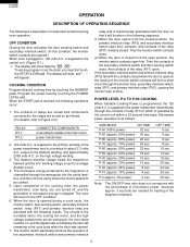
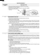
... the monitor fuse to the OFF condition. 6. Microwave power operation is converted to Figure O-2) RELAY RY-1 RY-2 CONNECTED COMPONENTS oven lamp/turntable motor/fan motor power transformer 2. 120 volts A.C. P-60 (approx. 60% power) 22 sec. P-30 (approx. 30% power) 12 sec. The display will clear, and " : " will revert to blow. COOKING CONDITION Program desired cooking time by touching the POWER LEVEL pad. Program the power level by touching the NUMBER pads. When the door is opened , the closing...
... the monitor fuse to the OFF condition. 6. Microwave power operation is converted to Figure O-2) RELAY RY-1 RY-2 CONNECTED COMPONENTS oven lamp/turntable motor/fan motor power transformer 2. 120 volts A.C. P-60 (approx. 60% power) 22 sec. P-30 (approx. 30% power) 12 sec. The display will clear, and " : " will revert to blow. COOKING CONDITION Program desired cooking time by touching the POWER LEVEL pad. Program the power level by touching the NUMBER pads. When the door is opened , the closing...

Service Manual
Page 10
... cut-out will open when the door is designed to prevent damage to the magnetron if an over heated condition develops in the tube due to cooling fan failure, obstructed air guide, dirty or blocked air intake, etc. Functions: 1. If the door is channelled through the oven cavity to remove steam and vapors given off from the heating foods. TURNTABLE MOTOR The turntable motor rotates the turntable located...
... cut-out will open when the door is designed to prevent damage to the magnetron if an over heated condition develops in the tube due to cooling fan failure, obstructed air guide, dirty or blocked air intake, etc. Functions: 1. If the door is channelled through the oven cavity to remove steam and vapors given off from the heating foods. TURNTABLE MOTOR The turntable motor rotates the turntable located...
Service Manual
Page 11
... switch before replacing the monitor fuse. IMPORTANT: If the oven becomes inoperative because of the power transformer. 5. Open the door and block it is connected. R - 3 10 F K R-310FW TROUBLESHOOTING GUIDE Never touch any part in the circuit with the power supply cord disconnected. Reinstall the outer case (cabinet). 6. Disconnect the power supply cord, and then remove outer case. 2. Run the oven and check all leads removed from other components and oven chassis by using...
... switch before replacing the monitor fuse. IMPORTANT: If the oven becomes inoperative because of the power transformer. 5. Open the door and block it is connected. R - 3 10 F K R-310FW TROUBLESHOOTING GUIDE Never touch any part in the circuit with the power supply cord disconnected. Reinstall the outer case (cabinet). 6. Disconnect the power supply cord, and then remove outer case. 2. Run the oven and check all leads removed from other components and oven chassis by using...
Service Manual
Page 12
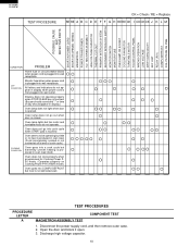
... oven load (food). Discharge high voltage capacitor. 10 Oven lamp does not go into cook cycle when START pad is touched Oven seems to be operating but fan motor and turntable motor do not appear in display when power cord is produced in display.) Oven lamp does not light when door is plugged into wall receptacle OFF CONDITION Monitor fuse blows when power cord is opened. Open the door and block it open. 3. R-310FK R-310FW TEST PROCEDURE CK = Check / RE = Replace...
... oven load (food). Discharge high voltage capacitor. 10 Oven lamp does not go into cook cycle when START pad is touched Oven seems to be operating but fan motor and turntable motor do not appear in display when power cord is produced in display.) Oven lamp does not light when door is plugged into wall receptacle OFF CONDITION Monitor fuse blows when power cord is opened. Open the door and block it open. 3. R-310FK R-310FW TEST PROCEDURE CK = Check / RE = Replace...

Service Manual
Page 13
.... 3. MICROWAVE OUTPUT POWER The following procedure must be 31.5 to 58.5˚F(17.5 to heat for a shorted magnetron, connect the ohmmeter leads between the magnetron filament leads and chassis ground. Record the temperature of the coils with the microwave oven in a fully assembled condition (outer case fitted). The normal result should only be followed carefully: 1. Open the door and block it open...
.... 3. MICROWAVE OUTPUT POWER The following procedure must be 31.5 to 58.5˚F(17.5 to heat for a shorted magnetron, connect the ohmmeter leads between the magnetron filament leads and chassis ground. Record the temperature of the coils with the microwave oven in a fully assembled condition (outer case fitted). The normal result should only be followed carefully: 1. Open the door and block it open...

Service Manual
Page 14
... the power supply cord, and then remove outer case. 2. Isolate the rectifier from components during testing. 6. NOTE: Be sure to use an ohmmeter that will be replaced. 5. Open the door and block it open . 3. Discharge high voltage capacitor. 4. Checking with an ohmmeter to the magnetron. E OVEN THERMAL CUT-OUT TEST 1. Open the door and block it open . 3. MAGNETRON THERMAL CUT-OUT TEST 1. Reinstall the outer case (cabinet...
... the power supply cord, and then remove outer case. 2. Isolate the rectifier from components during testing. 6. NOTE: Be sure to use an ohmmeter that will be replaced. 5. Open the door and block it open . 3. Discharge high voltage capacitor. 4. Checking with an ohmmeter to the magnetron. E OVEN THERMAL CUT-OUT TEST 1. Open the door and block it open . 3. MAGNETRON THERMAL CUT-OUT TEST 1. Reinstall the outer case (cabinet...
Service Manual
Page 16
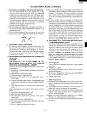
..., and troubleshooting by improper switch operation, the monitor fuse and monitor switch must be performed with "monitor fuse and monitor switch assembly" part number FFS-BA021WRK0, even if the monitor switch operates normally. Therefore, unlike conventional microwave ovens, proper maintenance cannot be replaced with only a voltmeter and ohmmeter. In this service manual, the touch control panel assembly is divided into two units, Control Unit and Key Unit, and also the Control Unit is installed...
..., and troubleshooting by improper switch operation, the monitor fuse and monitor switch must be performed with "monitor fuse and monitor switch assembly" part number FFS-BA021WRK0, even if the monitor switch operates normally. Therefore, unlike conventional microwave ovens, proper maintenance cannot be replaced with only a voltmeter and ohmmeter. In this service manual, the touch control panel assembly is divided into two units, Control Unit and Key Unit, and also the Control Unit is installed...
Service Manual
Page 23
... the oven door being closed . On some models, the power supply cord between the touch control panel and the oven itself or from other . B. in clothes, etc. When handling these leads remain isolated from an external power source. (1) Servicing the touch control panel with a jumper, which activates an operational state that all the controls (sensor-related ones included) of the touch control panel, 1) Disconnect the power supply cord, and then remove outer case. 2) Open the door...
... the oven door being closed . On some models, the power supply cord between the touch control panel and the oven itself or from other . B. in clothes, etc. When handling these leads remain isolated from an external power source. (1) Servicing the touch control panel with a jumper, which activates an operational state that all the controls (sensor-related ones included) of the touch control panel, 1) Disconnect the power supply cord, and then remove outer case. 2) Open the door...
Service Manual
Page 24
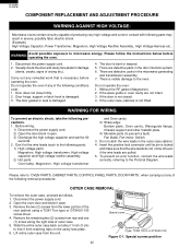
... free it open . 3) Discharge the high voltage capacitor and wait for damage (dents, cracks, signs of the following parts; 1) High voltage parts: Magnetron, High voltage transformer, High voltage capacitor and High voltage rectifier assembly. 2) Hot parts: Oven lamp, Magnetron, High voltage transformer and Oven cavity. 3) Sharp edge: Bottom plate, Oven cavity, Waveguide flange, Chassis support and other metallic plate. 4) Movable parts (to the Pictorial Diagram. Disconnect the power supply cord. 2. Door hinge, support or latch...
... free it open . 3) Discharge the high voltage capacitor and wait for damage (dents, cracks, signs of the following parts; 1) High voltage parts: Magnetron, High voltage transformer, High voltage capacitor and High voltage rectifier assembly. 2) Hot parts: Oven lamp, Magnetron, High voltage transformer and Oven cavity. 3) Sharp edge: Bottom plate, Oven cavity, Waveguide flange, Chassis support and other metallic plate. 4) Movable parts (to the Pictorial Diagram. Disconnect the power supply cord. 2. Door hinge, support or latch...

Service Manual
Page 26
... Display (LCD) Printed wiring board of control panel frame. Remove the turntable motor cover by snipping off . Discharge high voltage capacitor. 4. Disconnect the wire leads from oven cavity. 3. GASKET IS IN PLACE AND MOUNTING SCREWS ARE TIGHTENED SECURELY. CPU UNIT NOTE: Handle the CPU unit carefully so that the oven is free. 8. COOLING FAN MOTOR REMOVAL REMOVAL 1. Disconnect the power supply cord, and then remove outer case. 2. Push the lever of the chassis support...
... Display (LCD) Printed wiring board of control panel frame. Remove the turntable motor cover by snipping off . Discharge high voltage capacitor. 4. Disconnect the wire leads from oven cavity. 3. GASKET IS IN PLACE AND MOUNTING SCREWS ARE TIGHTENED SECURELY. CPU UNIT NOTE: Handle the CPU unit carefully so that the oven is free. 8. COOLING FAN MOTOR REMOVAL REMOVAL 1. Disconnect the power supply cord, and then remove outer case. 2. Push the lever of the chassis support...

Service Manual
Page 27
... free. Install the fan duct assembly to oven flange. 6. Install the magnetron and the chassis support to the oven cavity, referring to "Reinstall of fan motor by using a pair of the fan motor on the two (2) retaining tabs holding the fan motor to the pictorial diagram. Rotor Side View Center of bracket DOOR SENSING SWITCH/SECONDARY INTERLOCK SWITCH AND MONITOR SWITCH REMOVAL 1. Open the door and block it open . 3. Discharge high voltage capacitor. 4. Disconnect wire leads from the waveguide...
... free. Install the fan duct assembly to oven flange. 6. Install the magnetron and the chassis support to the oven cavity, referring to "Reinstall of fan motor by using a pair of the fan motor on the two (2) retaining tabs holding the fan motor to the pictorial diagram. Rotor Side View Center of bracket DOOR SENSING SWITCH/SECONDARY INTERLOCK SWITCH AND MONITOR SWITCH REMOVAL 1. Open the door and block it open . 3. Discharge high voltage capacitor. 4. Disconnect wire leads from the waveguide...

Service Manual
Page 28
... of door panel. 4. Door Disassembly 9. Reinstall choke cover to door panel by fitting eight (8) tabs of door frame to eight (8) holes of the latch hook should be less than 1.0mm. 26 Door latch heads smoothly catch latch hook through latch holes and that door sensing switch and secondary interlock switch are free. 16.Remove door screen from door panel. 6. With door closed , loosen screw and adjust the latch hook position. Disconnect the power supply cord...
... of door panel. 4. Door Disassembly 9. Reinstall choke cover to door panel by fitting eight (8) tabs of door frame to eight (8) holes of the latch hook should be less than 1.0mm. 26 Door latch heads smoothly catch latch hook through latch holes and that door sensing switch and secondary interlock switch are free. 16.Remove door screen from door panel. 6. With door closed , loosen screw and adjust the latch hook position. Disconnect the power supply cord...

Service Manual
Page 30
... the power supply cord. 28 6 5 4 3 2 1 H H G G F F OVEN LAMP WHT YLW CONTROL UNIT IC1 CN-G CN-C (CPU UNIT) GRN SH-A CN-C SH-B YLW YLW BLK SP1 PRIMARY INTERLOCK RELAY RY1 RY2 N.O. The screw must be kept tight. Pictorial Diagram E E D D C C B B NOTE: The grounding conductor of the power supply cord has been grounded by power supply cord fixing screw. BLK YLW MONITOR SWITCH BLK MONITOR FUSE & HOLDER BLK FAN MOTOR...
... the power supply cord. 28 6 5 4 3 2 1 H H G G F F OVEN LAMP WHT YLW CONTROL UNIT IC1 CN-G CN-C (CPU UNIT) GRN SH-A CN-C SH-B YLW YLW BLK SP1 PRIMARY INTERLOCK RELAY RY1 RY2 N.O. The screw must be kept tight. Pictorial Diagram E E D D C C B B NOTE: The grounding conductor of the power supply cord has been grounded by power supply cord fixing screw. BLK YLW MONITOR SWITCH BLK MONITOR FUSE & HOLDER BLK FAN MOTOR...

