
Service Manual
Page 1
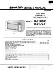
... ACCESSORIES ...42 SHARP CORPORATION This document has been published to those specified should be restored to its original condition and only parts identical to be used for after sales service only. WARNING TO SERVICE PERSONNEL: Microwave ovens contain circuitry... capable of user-safety the oven should be used . The contents are subject to change without notice. 1000W/ R-21JV COMMERCIAL MICROWAVE OVEN R-21JV-F R-21HT-F R-21JV-F SERVICE MANUAL S0515R21HTPF/ LIGHT DUTY COMMERCIAL MICROWAVE OVENS MODELS R-21HT-F ON...
... ACCESSORIES ...42 SHARP CORPORATION This document has been published to those specified should be restored to its original condition and only parts identical to be used for after sales service only. WARNING TO SERVICE PERSONNEL: Microwave ovens contain circuitry... capable of user-safety the oven should be used . The contents are subject to change without notice. 1000W/ R-21JV COMMERCIAL MICROWAVE OVEN R-21JV-F R-21HT-F R-21JV-F SERVICE MANUAL S0515R21HTPF/ LIGHT DUTY COMMERCIAL MICROWAVE OVENS MODELS R-21HT-F ON...
Service Manual
Page 2
... until the oven has been brought into compliance. The owner of the unit should inform SHARP ELECTRONICS CORPORATION of 4mW/cm2. R-21HT-F R-21JV-F PRECAUTIONS TO BE OBSERVED BEFORE AND DURING SERVICING TO AVOID POSSIBLE EXPOSURE TO EXCESSIVE MICROWAVE ENERGY (a) Do not operate or allow the oven to be operated with the door open...
... until the oven has been brought into compliance. The owner of the unit should inform SHARP ELECTRONICS CORPORATION of 4mW/cm2. R-21HT-F R-21JV-F PRECAUTIONS TO BE OBSERVED BEFORE AND DURING SERVICING TO AVOID POSSIBLE EXPOSURE TO EXCESSIVE MICROWAVE ENERGY (a) Do not operate or allow the oven to be operated with the door open...
Service Manual
Page 3
...be disconnected. Ensure that procedure, reconnect the power supply cord. Open the door and block it open. 3. R-21HT-F R-21JV-F WARNING TO SERVICE PERSONNEL Microwave ovens contain circuitry capable of producing very high voltage and current, contact with the use of an insulated screwdriver. Don't Touch... Run the oven and check all leads removed from other components and oven chassis by using insulation tape. 6. Reconnect all functions. Microwave ovens should be run empty. To test for two (2) minutes. When the two minutes has elapsed (timer at zero) carefully ...
...be disconnected. Ensure that procedure, reconnect the power supply cord. Open the door and block it open. 3. R-21HT-F R-21JV-F WARNING TO SERVICE PERSONNEL Microwave ovens contain circuitry capable of producing very high voltage and current, contact with the use of an insulated screwdriver. Don't Touch... Run the oven and check all leads removed from other components and oven chassis by using insulation tape. 6. Reconnect all functions. Microwave ovens should be run empty. To test for two (2) minutes. When the two minutes has elapsed (timer at zero) carefully ...

Service Manual
Page 4
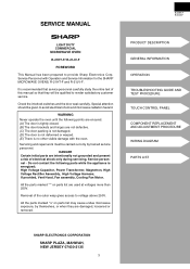
... beginning the actual measurement of the oven cavity. R-21HT-F R-21JV-F MICROWAVE MEASUREMENT PROCEDURE A. The placing of the oven. Requirements: 1) Microwave leakage limit (Power density limit): The power density of microwave radiation emitted by a microwave oven should not exceed 1mW/cm2 at any point 5cm or ...from the external surface of the oven. 2) Safety interlock switches Primary interlock relay and door sensing switch shall prevent microwave radiation emission in excess of the requirement as is permitted by the performance standard for instrumentation as prescribed by the closed...
... beginning the actual measurement of the oven cavity. R-21HT-F R-21JV-F MICROWAVE MEASUREMENT PROCEDURE A. The placing of the oven. Requirements: 1) Microwave leakage limit (Power density limit): The power density of microwave radiation emitted by a microwave oven should not exceed 1mW/cm2 at any point 5cm or ...from the external surface of the oven. 2) Safety interlock switches Primary interlock relay and door sensing switch shall prevent microwave radiation emission in excess of the requirement as is permitted by the performance standard for instrumentation as prescribed by the closed...
Service Manual
Page 5
It is no other visible damage with Operation and Service Information for the SHARP MICROWAVE OVENS, R-21HT-F and R-21JV-F. WARNING Never operate the oven until the following parts while the appliance is energized; If provided, Vent Hood, Fan assembly, Cooling Fan Motor. All the ...
It is no other visible damage with Operation and Service Information for the SHARP MICROWAVE OVENS, R-21HT-F and R-21JV-F. WARNING Never operate the oven until the following parts while the appliance is energized; If provided, Vent Hood, Fan assembly, Cooling Fan Motor. All the ...
Service Manual
Page 6
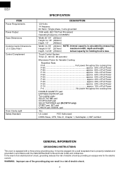
... local codes and ordinances. Depth 14-5/8" (370mm) Actual capacity for the electric current. Touch Control System Timer (0 - 99 min. 99 seconds) Microwave Power for Variable Cooking Repetition Rate; R-21HT-F R-21JV-F ITEM Power Requirements Power Output Case Dimensions Cooking Cavity Dimensions (1.0 Cubic Feet ) Control Complement Oven Cavity Light Safety Standard SPECIFICATION DESCRIPTION 120...
... local codes and ordinances. Depth 14-5/8" (370mm) Actual capacity for the electric current. Touch Control System Timer (0 - 99 min. 99 seconds) Microwave Power for Variable Cooking Repetition Rate; R-21HT-F R-21JV-F ITEM Power Requirements Power Output Case Dimensions Cooking Cavity Dimensions (1.0 Cubic Feet ) Control Complement Oven Cavity Light Safety Standard SPECIFICATION DESCRIPTION 120...

Service Manual
Page 8
... secondary interlock switch and door sensing switch close . (2) When the door is opened , the closing of the magnetron filament. 6 Microwave power operation is plugged in the following sequence. (1) When the door opens from the open position, the monitor switch contacts open ....noise filter of the secondary interlock switch and control relay (RY3) and is mechanically associated with the contacts closed . R-21HT-F R-21JV-F OPERATION DESCRIPTION OF OPERATING SEQUENCE The following is touched, the following operations occur: 1. When the START pad is a description of ...
... secondary interlock switch and door sensing switch close . (2) When the door is opened , the closing of the magnetron filament. 6 Microwave power operation is plugged in the following sequence. (1) When the door opens from the open position, the monitor switch contacts open ....noise filter of the secondary interlock switch and control relay (RY3) and is mechanically associated with the contacts closed . R-21HT-F R-21JV-F OPERATION DESCRIPTION OF OPERATING SEQUENCE The following is touched, the following operations occur: 1. When the START pad is a description of ...

Service Manual
Page 9
THERMAL THERMAL CUT-OUT CUT-OUT 125˚C (OVEN) 145˚C (MAG.) A7 A3 POWER TRANSFORMER R-21HT-F R-21JV-F LINE BYPASS CAPACITOR 0.003300 F / AC 125V NOISE SUPPRESSION COIL LINE CROSS CAPACITOR 0.22 F AC250V AC120V 60 Hz N LINE BYPASS CAPACITOR...003300 F / AC 125V CONTROL UNIT B1 B2 DOOR SENSING OL SWITCH OVEN LAMP FM AM FAN ANTENNA MOTOR MOTOR SECONDARY INTERLOCK SWITCH Figure O-2 Oven Schematic-Microwave cooking Condition CAPACITOR 0.94 µF 2400V 7 COOKING TIME ENTERED. 4. NOISE FILTER NOTE: Indicates components with potential above 250 V. DOOR CLOSED. 2. ...
THERMAL THERMAL CUT-OUT CUT-OUT 125˚C (OVEN) 145˚C (MAG.) A7 A3 POWER TRANSFORMER R-21HT-F R-21JV-F LINE BYPASS CAPACITOR 0.003300 F / AC 125V NOISE SUPPRESSION COIL LINE CROSS CAPACITOR 0.22 F AC250V AC120V 60 Hz N LINE BYPASS CAPACITOR...003300 F / AC 125V CONTROL UNIT B1 B2 DOOR SENSING OL SWITCH OVEN LAMP FM AM FAN ANTENNA MOTOR MOTOR SECONDARY INTERLOCK SWITCH Figure O-2 Oven Schematic-Microwave cooking Condition CAPACITOR 0.94 µF 2400V 7 COOKING TIME ENTERED. 4. NOISE FILTER NOTE: Indicates components with potential above 250 V. DOOR CLOSED. 2. ...
Service Manual
Page 11
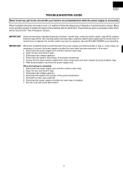
... in the "Test Procedure "section. Discharge high voltage capacitor. 4. Use part FFS-BA015WRK0 as an assembly. Ensure that procedure, reconnect the power supply cord. R-21HT-F R-21JV-F TROUBLESHOOTING GUIDE Never touch any part in the circuit with the power supply cord disconnected. After that the leads remain isolated from other components and.... Reconnect the leads to the primary of the power transformer. 5. IMPORTANT: If the oven becomes inoperative because of Operation in this event, 1. When troubleshooting the microwave oven, it is completed 1.
... in the "Test Procedure "section. Discharge high voltage capacitor. 4. Use part FFS-BA015WRK0 as an assembly. Ensure that procedure, reconnect the power supply cord. R-21HT-F R-21JV-F TROUBLESHOOTING GUIDE Never touch any part in the circuit with the power supply cord disconnected. After that the leads remain isolated from other components and.... Reconnect the leads to the primary of the power transformer. 5. IMPORTANT: If the oven becomes inoperative because of Operation in this event, 1. When troubleshooting the microwave oven, it is completed 1.

Service Manual
Page 13
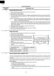
...On the R x 1 scale, the resistance of the primary coil should be less than 1 ohm and the resistance of the filament coil should be replaced. 6. MICROWAVE OUTPUT POWER The following components or wiring: silicon rectifier, high voltage capacitor and power transformer. For accurate results, the following procedure must be approximately 85... ohmmeter leads between the magnetron filament leads and chassis ground. Reconnect the power supply cord after the outer case is installed. 8. R-21HT-F R-21JV-F PROCEDURE LETTER A TEST PROCEDURES COMPONENT TEST MAGNETRON ASSEMBLY TEST 1.
...On the R x 1 scale, the resistance of the primary coil should be less than 1 ohm and the resistance of the filament coil should be replaced. 6. MICROWAVE OUTPUT POWER The following components or wiring: silicon rectifier, high voltage capacitor and power transformer. For accurate results, the following procedure must be approximately 85... ohmmeter leads between the magnetron filament leads and chassis ground. Reconnect the power supply cord after the outer case is installed. 8. R-21HT-F R-21JV-F PROCEDURE LETTER A TEST PROCEDURES COMPONENT TEST MAGNETRON ASSEMBLY TEST 1.
Service Manual
Page 16
...Before testing, 1) Disconnect the power supply cord, and then remove outer case. 2) Open the door and block it open. 3. Therefore, unlike conventional microwave ovens, proper maintenance cannot be replaced with only a voltmeter and ohmmeter. Using an ohmmeter, check between the terminals LINE CROSS CAPACITOR 0.22 F AC250V ...J TOUCH CONTROL PANEL ASSEMBLY TEST The touch control panel consists of a 20 ampere fuse and switch. 5. R-21HT-F R-21JV-F PROCEDURE LETTER H TEST PROCEDURES COMPONENT TEST BLOWN MONITOR FUSE TEST 1. Discharge high voltage capacitor. 4.
...Before testing, 1) Disconnect the power supply cord, and then remove outer case. 2) Open the door and block it open. 3. Therefore, unlike conventional microwave ovens, proper maintenance cannot be replaced with only a voltmeter and ohmmeter. Using an ohmmeter, check between the terminals LINE CROSS CAPACITOR 0.22 F AC250V ...J TOUCH CONTROL PANEL ASSEMBLY TEST The touch control panel consists of a 20 ampere fuse and switch. 5. R-21HT-F R-21JV-F PROCEDURE LETTER H TEST PROCEDURES COMPONENT TEST BLOWN MONITOR FUSE TEST 1. Discharge high voltage capacitor. 4.

Service Manual
Page 18
...supply cord, and then remove outer case. 2. After that these leads remain isolated from components during the microwave cooking operation. DC. CONNECTED COMPONENTS Power transformer Oven lamp / Antenna motor / Cooling fan motor 8. Open...G 1 G 2 G 3 G 4 G 5 G 6 G 7 G 8 G 9 G10 G11 7 DOUBLE QUANTITY START SET 8 SELECTA EXPRESS STOP/ TIME DEFROST CLEAR CHECK 9 5 3 1 SIGNAL G12 0 6 4 2 R-21JV-F G 1 G 2 G 3 G 4 G 5 G 6 G 7 G 8 G 9 G10 G11 G12 17 7 18 8 19 9 20 0 R-21HT-F SELECTA DOUBLE POWER QUANTITY START SELECTA EXPRESS STOP/ TIME DEFROST CLEAR 15...
...supply cord, and then remove outer case. 2. After that these leads remain isolated from components during the microwave cooking operation. DC. CONNECTED COMPONENTS Power transformer Oven lamp / Antenna motor / Cooling fan motor 8. Open...G 1 G 2 G 3 G 4 G 5 G 6 G 7 G 8 G 9 G10 G11 7 DOUBLE QUANTITY START SET 8 SELECTA EXPRESS STOP/ TIME DEFROST CLEAR CHECK 9 5 3 1 SIGNAL G12 0 6 4 2 R-21JV-F G 1 G 2 G 3 G 4 G 5 G 6 G 7 G 8 G 9 G10 G11 G12 17 7 18 8 19 9 20 0 R-21HT-F SELECTA DOUBLE POWER QUANTITY START SELECTA EXPRESS STOP/ TIME DEFROST CLEAR 15...
Service Manual
Page 24
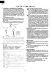
...sometimes it is not fully protected by the surrounding high voltage power source, static electricity charge in clothes, etc. Shapes of the microwave oven and the precautions you must take when doing so. A. On some models, the power supply cord between the touch control ...or more advanced model. 3) Others: Hand tools 5. As for Handling Electronic Components This unit uses CMOS LSI in protection circuit. R-21HT-F R-21JV-F TOUCH CONTROL PANEL SERVICING 1. Precautions for the sensor-related controls of the touch control panel, checking them in aluminium foil. 2) When soldering,...
...sometimes it is not fully protected by the surrounding high voltage power source, static electricity charge in clothes, etc. Shapes of the microwave oven and the precautions you must take when doing so. A. On some models, the power supply cord between the touch control ...or more advanced model. 3) Others: Hand tools 5. As for Handling Electronic Components This unit uses CMOS LSI in protection circuit. R-21HT-F R-21JV-F TOUCH CONTROL PANEL SERVICING 1. Precautions for the sensor-related controls of the touch control panel, checking them in aluminium foil. 2) When soldering,...
Service Manual
Page 25
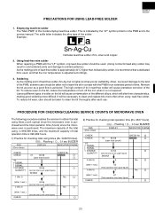
... (service total count lower figure) . 2) Practice for checking total operation time (Ex. 4567 hours). PRECAUTIONS FOR USING LEAD-FREE SOLDER R-21HT-F R-21JV-F 1. Example: Sn-Ag-Cu Indicates lead-free solder of the different alloys, which will be taken to clean and replace bits more difficult. Remove ... solder on the bit will cause premature corrosion of this model employs lead-free solder. PROCEDURE FOR CHECKING/CLEARING SERVICE COUNTS OF MICROWAVE OVEN The following procedure enables the servicer to printed patterns.) As the melting point of the solder. This is indicated by the...
... (service total count lower figure) . 2) Practice for checking total operation time (Ex. 4567 hours). PRECAUTIONS FOR USING LEAD-FREE SOLDER R-21HT-F R-21JV-F 1. Example: Sn-Ag-Cu Indicates lead-free solder of the different alloys, which will be taken to clean and replace bits more difficult. Remove ... solder on the bit will cause premature corrosion of this model employs lead-free solder. PROCEDURE FOR CHECKING/CLEARING SERVICE COUNTS OF MICROWAVE OVEN The following procedure enables the servicer to printed patterns.) As the melting point of the solder. This is indicated by the...
Service Manual
Page 28
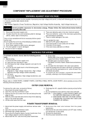
... parts: Oven lamp, Magnetron, High voltage transformer, and Oven cavity. 3) Sharp edge: Bottom plate, Oven cavity, Waveguide flange, Chassis support and other metallic plate. 4) Movable parts (to microwave energy. Open the oven door and block it open . 3. The door ...damaged. 3. WARNING: Avoid possible exposure operating the oven. There are not intact. 3. R-21HT-F R-21JV-F COMPONENT REPLACEMENT AND ADJUSTMENT PROCEDURE WARNING AGAINST HIGH VOLTAGE: Microwave ovens contain circuitry capable of producing very high voltage and current, contact with the outer case removed. Remove...
... parts: Oven lamp, Magnetron, High voltage transformer, and Oven cavity. 3) Sharp edge: Bottom plate, Oven cavity, Waveguide flange, Chassis support and other metallic plate. 4) Movable parts (to microwave energy. Open the oven door and block it open . 3. The door ...damaged. 3. WARNING: Avoid possible exposure operating the oven. There are not intact. 3. R-21HT-F R-21JV-F COMPONENT REPLACEMENT AND ADJUSTMENT PROCEDURE WARNING AGAINST HIGH VOLTAGE: Microwave ovens contain circuitry capable of producing very high voltage and current, contact with the outer case removed. Remove...

Service Manual
Page 32
...remove the glass stopper R. 14.Slide the front door glass and the sealer plate left at first and then slide upwards to Microwave Measurement Procedure.) Handle Lever Latch Head Latch Hook Door Handle Latch Switch Lever A Latch Lever Secondary Interlock Switch Latch Switch Lever... contacts close when door is free from the tabs holding the door case to prevent microwave leakage. Insert a putty knife (thickness of door remains less than 0.5mm. 2. DOOR PANEL REMOVAL 9. R-21HT-F R-21JV-F After adjustment, check the following. 1. Disconnect the power supply cord. 2. Pry the...
...remove the glass stopper R. 14.Slide the front door glass and the sealer plate left at first and then slide upwards to Microwave Measurement Procedure.) Handle Lever Latch Head Latch Hook Door Handle Latch Switch Lever A Latch Lever Secondary Interlock Switch Latch Switch Lever... contacts close when door is free from the tabs holding the door case to prevent microwave leakage. Insert a putty knife (thickness of door remains less than 0.5mm. 2. DOOR PANEL REMOVAL 9. R-21HT-F R-21JV-F After adjustment, check the following. 1. Disconnect the power supply cord. 2. Pry the...
Service Manual
Page 33
...latch hole. 2. Therefore, occasional appearance of moisture, light or sensing of gentle warm air movement around door with an approved microwave survey meter. (Refer to Microwave Measurement Procedure.) Note: The door on the tab of the oven cavity bottom plate. 8. Disconnect the power supply cord.... (1) screw. Pin Upper Oven Hinge Upper Oven Hinge Door Panel Lower Oven Hinge Slit Chok Choke Cover Lower Oven Pin Hinge R-21HT-F R-21JV-F Figure C-7. Open the door and block it open. 3. Remove the stirrer antenna assembly from the oven cavity bottom plate, referring to "...
...latch hole. 2. Therefore, occasional appearance of moisture, light or sensing of gentle warm air movement around door with an approved microwave survey meter. (Refer to Microwave Measurement Procedure.) Note: The door on the tab of the oven cavity bottom plate. 8. Disconnect the power supply cord.... (1) screw. Pin Upper Oven Hinge Upper Oven Hinge Door Panel Lower Oven Hinge Slit Chok Choke Cover Lower Oven Pin Hinge R-21HT-F R-21JV-F Figure C-7. Open the door and block it open. 3. Remove the stirrer antenna assembly from the oven cavity bottom plate, referring to "...

Service Manual
Page 34
... rubber packing is installed. Make sure that the smooth surface of the ceramic shelf. The one (1) rubber packing without a fin are attached to excessive microwave energy. R-21HT-F R-21JV-F To left wall of Flat face oven cavity Antenna motor shaft Antenna holder Hole To right wall of Antenna Motor Shaft and Stirrer Antenna...
... rubber packing is installed. Make sure that the smooth surface of the ceramic shelf. The one (1) rubber packing without a fin are attached to excessive microwave energy. R-21HT-F R-21JV-F To left wall of Flat face oven cavity Antenna motor shaft Antenna holder Hole To right wall of Antenna Motor Shaft and Stirrer Antenna...

Service Manual
Page 39
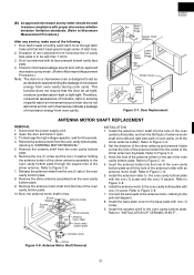
PART NO. The parts marked "*" are used in voltage more than 250V. NO. R-21HT-F R-21JV-F PARTS LIST Note: The parts marked "∆" may cause undue microwave exposure. DESCRIPTION Q'TY 1- 1 1- 2 1- 3 1- 4 * 1- 5 * 1- 6 1- 7 1- 8 1- 9 1-10 1-10 1-11 1-12 1-13 * 1-14 ∆* 1-15 2- 1 2- 1 2- 2 2- 3 2- 4 2-...Magnetron 1 CABINET PARTS GCABUA672WRP0 Outer case cabinet [R-21HT-F] 1 GCABUA674WRP0 Outer case cabinet [R-21JV-F] 1 GDAI-A311WRW0 Base plate 1 GCOVHA406WRW0 Base plate cover 1 GLEGPA074WRE0 Foot 2 GLEGPA076WRF0 Leg 1 CONTROL PANEL PARTS 3- 1 DPWBFB808WRU0 Control...
PART NO. The parts marked "*" are used in voltage more than 250V. NO. R-21HT-F R-21JV-F PARTS LIST Note: The parts marked "∆" may cause undue microwave exposure. DESCRIPTION Q'TY 1- 1 1- 2 1- 3 1- 4 * 1- 5 * 1- 6 1- 7 1- 8 1- 9 1-10 1-10 1-11 1-12 1-13 * 1-14 ∆* 1-15 2- 1 2- 1 2- 2 2- 3 2- 4 2-...Magnetron 1 CABINET PARTS GCABUA672WRP0 Outer case cabinet [R-21HT-F] 1 GCABUA674WRP0 Outer case cabinet [R-21JV-F] 1 GDAI-A311WRW0 Base plate 1 GCOVHA406WRW0 Base plate cover 1 GLEGPA074WRE0 Foot 2 GLEGPA076WRF0 Leg 1 CONTROL PANEL PARTS 3- 1 DPWBFB808WRU0 Control...


