
Service Manual
Page 1
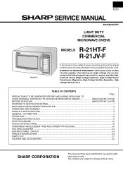
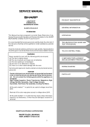
... EXPOSURE TO EXCESSIVE MICROWAVE ENERGY INSIDE FRONT COVER BEFORE SERVICING ...INSIDE FRONT COVER WARNING TO SERVICE PERSONNEL ...1 MICROWAVE MEASUREMENT PROCEDURE 2 FOREWORD AND WARNING ...3 PRODUCT SPECIFICATIONS ...4 GENERAL INFORMATION ...4 OPERATION ...6 TROUBLESHOOTING GUIDE ...9 TEST PROCEDURE ...10 TOUCH CONTROL PANEL ...18 COMPONENT REPLACEMENT AND ADJUSTMENT PROCEDURE 26 PICTORIAL DIAGRAM ...33 CONTROL PANEL CIRCUIT ...34 PRINTED WIRING BOARD ...36 PARTS LIST ...37 PACKING AND ACCESSORIES ...42 SHARP CORPORATION This document has been published to change without notice.
... EXPOSURE TO EXCESSIVE MICROWAVE ENERGY INSIDE FRONT COVER BEFORE SERVICING ...INSIDE FRONT COVER WARNING TO SERVICE PERSONNEL ...1 MICROWAVE MEASUREMENT PROCEDURE 2 FOREWORD AND WARNING ...3 PRODUCT SPECIFICATIONS ...4 GENERAL INFORMATION ...4 OPERATION ...6 TROUBLESHOOTING GUIDE ...9 TEST PROCEDURE ...10 TOUCH CONTROL PANEL ...18 COMPONENT REPLACEMENT AND ADJUSTMENT PROCEDURE 26 PICTORIAL DIAGRAM ...33 CONTROL PANEL CIRCUIT ...34 PRINTED WIRING BOARD ...36 PARTS LIST ...37 PACKING AND ACCESSORIES ...42 SHARP CORPORATION This document has been published to change without notice.
Service Manual
Page 2
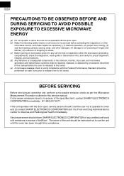
...-4277. If the unit operates with the door open . (b) Make the following safety checks on all ovens to be serviced before the oven is released to the owner. (e) A microwave leakage check to verify compliance with the Federal Performance Standard should inform SHARP ELECTRONICS CORPORATION of any service test or inspection within the microwave generating compartments, check the magnetron, wave guide or transmission line, and...
...-4277. If the unit operates with the door open . (b) Make the following safety checks on all ovens to be serviced before the oven is released to the owner. (e) A microwave leakage check to verify compliance with the Federal Performance Standard should inform SHARP ELECTRONICS CORPORATION of any service test or inspection within the microwave generating compartments, check the magnetron, wave guide or transmission line, and...
Service Manual
Page 3
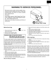
..... Open the door and block it open. 3. Reconnect the power supply cord after the oven has been switched off. Read the Service Manual carefully and follow all service work is completed and the oven is installed. 7. Disconnect the power supply cord , remove outer case. 2. DISCHARGE THE HIGH-VOLTAGE CAPACITOR BEFORE SERVICING. Ensure that procedure, reconnect the power supply cord. Open the door and block it open . 3. Microwave ovens should be run empty. When all instructions. The...
..... Open the door and block it open. 3. Reconnect the power supply cord after the oven has been switched off. Read the Service Manual carefully and follow all service work is completed and the oven is installed. 7. Disconnect the power supply cord , remove outer case. 2. DISCHARGE THE HIGH-VOLTAGE CAPACITOR BEFORE SERVICING. Ensure that procedure, reconnect the power supply cord. Open the door and block it open . 3. Microwave ovens should be run empty. When all instructions. The...

Service Manual
Page 4
... Power Cooking Mode 5) Close the door and select a cook cycle of this standard load in ./sec. (2.5 cm/sec.) along the gap, watching for the maximum indication on the meter. 3) Check for leakage around the switches, indicator, and vents). Important: Survey instruments that the actual instrument is measured accurately. 4) Set the cooking control on service invoice and microwave leakage report. 2 C. Leakage test: Closed-door...
... Power Cooking Mode 5) Close the door and select a cook cycle of this standard load in ./sec. (2.5 cm/sec.) along the gap, watching for the maximum indication on the meter. 3) Check for leakage around the switches, indicator, and vents). Important: Survey instruments that the actual instrument is measured accurately. 4) Set the cooking control on service invoice and microwave leakage report. 2 C. Leakage test: Closed-door...
Service Manual
Page 5
... visible damage with Operation and Service Information for the SHARP MICROWAVE OVENS, R-21HT-F and R-21JV-F. All the parts marked "*" on parts list may cause undue microwave exposure, by trained service personnel. R-21HT-F R-21JV-F PRODUCT DESCRIPTION GENERAL INFORMATION OPERATION TROUBLESHOOTING GUIDE AND TEST PROCEDURE TOUCH CONTROL PANEL COMPONENT REPLACEMENT AND ADJUSTMENT PROCEDURE WIRING DIAGRAM PARTS LIST SHARP ELECTRONICS CORPORATION SHARP PLAZA, MAHWAH, NEW JERSEY 07430-2135 3 Check the interlock switches and the door seal carefully. Servicing and repair work must be...
... visible damage with Operation and Service Information for the SHARP MICROWAVE OVENS, R-21HT-F and R-21JV-F. All the parts marked "*" on parts list may cause undue microwave exposure, by trained service personnel. R-21HT-F R-21JV-F PRODUCT DESCRIPTION GENERAL INFORMATION OPERATION TROUBLESHOOTING GUIDE AND TEST PROCEDURE TOUCH CONTROL PANEL COMPONENT REPLACEMENT AND ADJUSTMENT PROCEDURE WIRING DIAGRAM PARTS LIST SHARP ELECTRONICS CORPORATION SHARP PLAZA, MAHWAH, NEW JERSEY 07430-2135 3 Check the interlock switches and the door seal carefully. Servicing and repair work must be...
Service Manual
Page 6
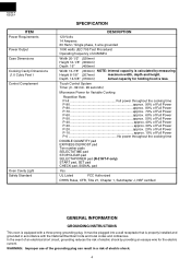
... EXPRESS DEFROST pad Ten number pads SELECTATIME pad STOP/CLEAR pad SELECTAPOWER pad (R-21HT-F only) START pad, SET pad CHECK pad, SIGNAL pad Yes UL Listed FCC Authorized DHHS Rules, CFR, Title 21, Chapter 1, Subchapter J, NSF certified GENERAL INFORMATION GROUNDING INSTRUCTIONS This oven is equipped with the National Electrical Code and local codes and ordinances. Touch Control System Timer (0 - 99 min. 99 seconds) Microwave Power for holding food...
... EXPRESS DEFROST pad Ten number pads SELECTATIME pad STOP/CLEAR pad SELECTAPOWER pad (R-21HT-F only) START pad, SET pad CHECK pad, SIGNAL pad Yes UL Listed FCC Authorized DHHS Rules, CFR, Title 21, Chapter 1, Subchapter J, NSF certified GENERAL INFORMATION GROUNDING INSTRUCTIONS This oven is equipped with the National Electrical Code and local codes and ordinances. Touch Control System Timer (0 - 99 min. 99 seconds) Microwave Power for holding food...

Service Manual
Page 7
... sound 5 7 9 10 R-21HT-F 5 6 85 11 9 10 6 8 11 R-21JV-F SIGNAL pad for setting variable power level 4 4 8. Control panel 11 4 6. Air intake openings 16. EXPRESS DEFROST pad 2 32 3 4. Ten number pads for time and memory programming 5. Where a two-pronged wall-receptacle is encountered, it replaced with see-through window 14. Door latches 16 9. Outer case cabinet 13.Air ventilation cover and openings TOUCH CONTROL PANEL 1. touch to operate oven after door is closed and time is provided to stop operation...
... sound 5 7 9 10 R-21HT-F 5 6 85 11 9 10 6 8 11 R-21JV-F SIGNAL pad for setting variable power level 4 4 8. Control panel 11 4 6. Air intake openings 16. EXPRESS DEFROST pad 2 32 3 4. Ten number pads for time and memory programming 5. Where a two-pronged wall-receptacle is encountered, it replaced with see-through window 14. Door latches 16 9. Outer case cabinet 13.Air ventilation cover and openings TOUCH CONTROL PANEL 1. touch to operate oven after door is closed and time is provided to stop operation...

Service Manual
Page 8
... circuit through the waveguide into the cavity feed-box, and then into the cavity where the food is programmed, the 120 volts A.C. The microwave energy produced by touching SELECTATIME pad and the NUMBER pads. OFF CONDITION Closing the door activates door sensing switch and secondary interlock switch. (In this condition, the monitor switch contacts are needed for heating of the control unit (Figure O-1). 1. COOKING CONDITION Program desired cooking time...
... circuit through the waveguide into the cavity feed-box, and then into the cavity where the food is programmed, the 120 volts A.C. The microwave energy produced by touching SELECTATIME pad and the NUMBER pads. OFF CONDITION Closing the door activates door sensing switch and secondary interlock switch. (In this condition, the monitor switch contacts are needed for heating of the control unit (Figure O-1). 1. COOKING CONDITION Program desired cooking time...

Service Manual
Page 10
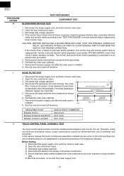
... oven to render the oven inoperative, by improper setting of the cooking time or failure of the latch hook. It is then exhausted through the air vanes surrounding the magnetron and cools the magnetron. The thermal cutout will be stopped. Under normal operation, the oven thermal cut -out will open . The latch switch lever A is activated by the latch switch lever A. When the door is mounted in the power circuit. 8 MONITOR SWITCH The monitor switch...
... oven to render the oven inoperative, by improper setting of the cooking time or failure of the latch hook. It is then exhausted through the air vanes surrounding the magnetron and cools the magnetron. The thermal cutout will be stopped. Under normal operation, the oven thermal cut -out will open . The latch switch lever A is activated by the latch switch lever A. When the door is mounted in the power circuit. 8 MONITOR SWITCH The monitor switch...

Service Manual
Page 12
... MONITOR SWITCH MONITOR FUSE TOUCH CONTROL PANEL KEY UNIT RELAY (RY3) FOIL PATTERN ON P.W.B. does not appear in oven load (food). Oven lamp lights but little or no heat is plugged into wall outlet. Oven lamp does not go into cook cycle when START pad is touched Oven seems to be operating but fan motor and antenna motor do not operate. Oven does not cook properly when programmed for Cooking Power 5 mode. (Operates properly on Cooking Power 10 (HIGH) mode.) ERROR MODE "EE9" Maximum time is...
... MONITOR SWITCH MONITOR FUSE TOUCH CONTROL PANEL KEY UNIT RELAY (RY3) FOIL PATTERN ON P.W.B. does not appear in oven load (food). Oven lamp lights but little or no heat is plugged into wall outlet. Oven lamp does not go into cook cycle when START pad is touched Oven seems to be operating but fan motor and antenna motor do not operate. Oven does not cook properly when programmed for Cooking Power 5 mode. (Operates properly on Cooking Power 10 (HIGH) mode.) ERROR MODE "EE9" Maximum time is...

Service Manual
Page 13
... water temperature) which would reduce cooking time. Operate oven at POWER 10(HIGH) selecting more than 1 ohm. 5. Check for an open . 3. Reinstall the outer case (cabinet). 7. Run the oven and check all leads removed from components during testing. 6. Disconnect the power supply cord, and then remove outer case. 2. Open the door and block it open filament, isolate the magnetron from the oven and again measure the temperature...
... water temperature) which would reduce cooking time. Operate oven at POWER 10(HIGH) selecting more than 1 ohm. 5. Check for an open . 3. Reinstall the outer case (cabinet). 7. Run the oven and check all leads removed from components during testing. 6. Disconnect the power supply cord, and then remove outer case. 2. Open the door and block it open filament, isolate the magnetron from the oven and again measure the temperature...

Service Manual
Page 14
.... 4. Checking with an ohmmeter to the magnetron. Open the door and block it open. 3. An open thermal cutout indicates overheating of control unit. Reconnect the power supply cord after the outer case is open . 3. Run the oven and check all functions. Check for improper setting of cooking time or operation of the magnetron. Discharge high voltage capacitor. 4. Reconnect all leads removed from components during testing. 6. Run the...
.... 4. Checking with an ohmmeter to the magnetron. Open the door and block it open. 3. An open thermal cutout indicates overheating of control unit. Reconnect the power supply cord after the outer case is open . 3. Run the oven and check all functions. Check for improper setting of cooking time or operation of the magnetron. Discharge high voltage capacitor. 4. Reconnect all leads removed from components during testing. 6. Run the...
Service Manual
Page 16
... of circuits including semiconductors such as described in the following table. Open the door and block it open . 3. Using an ohmmeter, check between the terminals LINE CROSS CAPACITOR 0.22 F AC250V L FUSE 20A as LSI, ICs, etc. Reinstall the outer case (cabinet). 7. Therefore, unlike conventional microwave ovens, proper maintenance cannot be replaced with only a voltmeter and ohmmeter. Disconnect the power supply cord, and then remove...
... of circuits including semiconductors such as described in the following table. Open the door and block it open . 3. Using an ohmmeter, check between the terminals LINE CROSS CAPACITOR 0.22 F AC250V L FUSE 20A as LSI, ICs, etc. Reinstall the outer case (cabinet). 7. Therefore, unlike conventional microwave ovens, proper maintenance cannot be replaced with only a voltmeter and ohmmeter. Disconnect the power supply cord, and then remove...

Service Manual
Page 18
... short the door sensing switch connecter). Reconnect the power supply cord after clearing the control unit) to the primary of the connector (A) on the control panel schematic and place a jumper wire between the pins that correspond to the relay coil. Reconnect all leads removed from components during the microwave cooking operation. voltmeter. DC. Approx. 12.0V D.C. CONNECTED COMPONENTS Power transformer Oven lamp / Antenna motor / Cooling fan motor 8. R-21HT-F R-21JV...
... short the door sensing switch connecter). Reconnect the power supply cord after clearing the control unit) to the primary of the connector (A) on the control panel schematic and place a jumper wire between the pins that correspond to the relay coil. Reconnect all leads removed from components during the microwave cooking operation. voltmeter. DC. Approx. 12.0V D.C. CONNECTED COMPONENTS Power transformer Oven lamp / Antenna motor / Cooling fan motor 8. R-21HT-F R-21JV...
Service Manual
Page 24
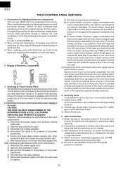
... built-in this reason, it is not applied to the oven door being sure that the lead wires are used. (2) Servicing the touch control panel with a jumper, which brings about an operational state that abnormal voltage due to use grounded soldering iron and work table. Connect an external power source to the power input terminal of the touch control panel, then it is possible to check and repair the controls...
... built-in this reason, it is not applied to the oven door being sure that the lead wires are used. (2) Servicing the touch control panel with a jumper, which brings about an operational state that abnormal voltage due to use grounded soldering iron and work table. Connect an external power source to the power input terminal of the touch control panel, then it is possible to check and repair the controls...
Service Manual
Page 28
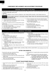
... plate. 5. Please follow the instructions below before operating the oven. Disconnect the power supply cord. 2. There are pulled. 5. Don't let the wire leads touch to the followiong parts; 1) High voltage parts: Magnetron, High voltage transformer, High voltage capacitor and High voltage rectifier assembly. 2) Hot parts: Oven lamp, Magnetron, High voltage transformer, and Oven cavity. 3) Sharp edge: Bottom plate, Oven cavity, Waveguide flange, Chassis support and other metallic plate. 4) Movable parts (to microwave energy. Do not operate the oven...
... plate. 5. Please follow the instructions below before operating the oven. Disconnect the power supply cord. 2. There are pulled. 5. Don't let the wire leads touch to the followiong parts; 1) High voltage parts: Magnetron, High voltage transformer, High voltage capacitor and High voltage rectifier assembly. 2) Hot parts: Oven lamp, Magnetron, High voltage transformer, and Oven cavity. 3) Sharp edge: Bottom plate, Oven cavity, Waveguide flange, Chassis support and other metallic plate. 4) Movable parts (to microwave energy. Do not operate the oven...

Service Manual
Page 29
... screw driver. 6. Disconnect the power supply cord and then remove outer case. 2. Now, the control unit is free. Pull the wire leads from the high voltage capacitor. 8. Now, the oven lamp socket is free. Oven lamp socket 27 Remove one (1) screw holding the control unit to the control panel frame. 10. Discharge high voltage capacitor. 4. Carefully remove four (4) screws holding the control panel assembly to the oven cavity rear plate. 10. GASKET IS IN PLACE AND THE MAGNETRON MOUNTING SCREWS...
... screw driver. 6. Disconnect the power supply cord and then remove outer case. 2. Now, the control unit is free. Pull the wire leads from the high voltage capacitor. 8. Now, the oven lamp socket is free. Oven lamp socket 27 Remove one (1) screw holding the control unit to the control panel frame. 10. Discharge high voltage capacitor. 4. Carefully remove four (4) screws holding the control panel assembly to the oven cavity rear plate. 10. GASKET IS IN PLACE AND THE MAGNETRON MOUNTING SCREWS...
Service Manual
Page 31
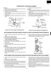
... power supply cord and then remove outer case. 2. If each switch. Disconnect the power supply cord and then remove outer case. 2. Open the door and block it open . 3. Re-install each switch in the upper position. 2. Oven Cavity Rear Plate Power Supply Cord Screw Green Wire Black Wire RED White Wire L WHT N Noise Filter Chassis Support 7. R-21HT-F R-21JV-F POWER SUPPLY CORD REPLACEMENT Removal 1. Remove the control panel assembly referring to the oven cavity front flange. 5. Power Supply Cord Replacement Figure C-3b. Secure latch hook (with the door...
... power supply cord and then remove outer case. 2. If each switch. Disconnect the power supply cord and then remove outer case. 2. Open the door and block it open . 3. Re-install each switch in the upper position. 2. Oven Cavity Rear Plate Power Supply Cord Screw Green Wire Black Wire RED White Wire L WHT N Noise Filter Chassis Support 7. R-21HT-F R-21JV-F POWER SUPPLY CORD REPLACEMENT Removal 1. Remove the control panel assembly referring to the oven cavity front flange. 5. Power Supply Cord Replacement Figure C-3b. Secure latch hook (with the door...

Service Manual
Page 32
... door glass and the sealer plate left at first and then slide upwards to prevent microwave leakage. DOOR CASE REMOVAL (After DOOR PANEL REMOVAL) 12.Straighten all door parts except the choke cover. 2. Re-install all tabs of door panel on the door panel assembly) to release them from the tab of the latch angle assembly. 13.Remove the two (2) screws holding the door handle and the latch angle assembly through the door frame. 14.Now, door handle is free...
... door glass and the sealer plate left at first and then slide upwards to prevent microwave leakage. DOOR CASE REMOVAL (After DOOR PANEL REMOVAL) 12.Straighten all door parts except the choke cover. 2. Re-install all tabs of door panel on the door panel assembly) to release them from the tab of the latch angle assembly. 13.Remove the two (2) screws holding the door handle and the latch angle assembly through the door frame. 14.Now, door handle is free...
Service Manual
Page 38
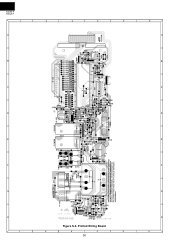
... PARTS WHILE THE APPLIANCE IS ENERGIZED ; Printed Wiring Board 2 3 4 5 36 6 A B C D E F G H 6 B (CN - D) 2 16 1 (R67) 9 (JJ) (R66) 8 (JH) (C101) (J5) (C64) (R65) C8 R4 (J6) C4 R40 SP1 10 (JB) (J9) (D10) (C10) Q22 (R102) E B B D21 E MICRO 1 MICRO ...2 RY2 (TB2) RY3 (14) (15) (16) (17) (CT1) (J1) (Q23) D22 11 (C100) (D100) (R100) (JA) (R1) Q1 (R2) (R101) (ZD1) C1 BE Q3 C2 C9 (TB1) 7 DANGER-CERTAIN PART IS INTENTIONALLY NOT GROUNDED AND MAY PRESENT A RISK OF ELECTRICAL SHOCK DURING SERVICING. TRANSFORMER S P P T1 12 VRS1 (VRS2) POWER POWER...
... PARTS WHILE THE APPLIANCE IS ENERGIZED ; Printed Wiring Board 2 3 4 5 36 6 A B C D E F G H 6 B (CN - D) 2 16 1 (R67) 9 (JJ) (R66) 8 (JH) (C101) (J5) (C64) (R65) C8 R4 (J6) C4 R40 SP1 10 (JB) (J9) (D10) (C10) Q22 (R102) E B B D21 E MICRO 1 MICRO ...2 RY2 (TB2) RY3 (14) (15) (16) (17) (CT1) (J1) (Q23) D22 11 (C100) (D100) (R100) (JA) (R1) Q1 (R2) (R101) (ZD1) C1 BE Q3 C2 C9 (TB1) 7 DANGER-CERTAIN PART IS INTENTIONALLY NOT GROUNDED AND MAY PRESENT A RISK OF ELECTRICAL SHOCK DURING SERVICING. TRANSFORMER S P P T1 12 VRS1 (VRS2) POWER POWER...

